What is a phase in electricity - definition of the concept
Phase in electricity is the colloquial name for a wire that is energized relative to another, which is called zero. This name comes from the fact that the current generated at substations and supplied to houses is variable, that is, the EMF created at substations have the same frequency (for Russia and the CIS countries it is 50 Hz), but are shifted relative to each other friend in time at a certain phase angle. Houses are usually supplied with all three phases and it does not matter which phase your apartment is connected to.
Figure 1. Electrics and electricity - schematic representation of phase, zero and ground
In Fig. 1 is a schematic diagram of the flow of electric current into the apartment from the general system. The letters $L1$, $L2$, $L3$ denote phases 1-3, and the letter $N$ denotes the neutral wire.
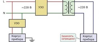
In Fig. Figure 2 shows a schematic connection of current to the apartment from the transformer, the letter $L_T$ denotes the phase on the transformer, the letter $L$ denotes the phase in the apartment, and the letter $R_H$ denotes a connected electrical appliance that has some resistance $R_H$.
There are 2 wires coming from the transformer, one is the so-called phase wire with voltage, and the other is the neutral wire, from which the grounding is carried out by placing the contact in the ground. There are other sources of grounding besides the ground itself; in these figures, grounding is indicated by the letters $Zml$.
In Fig. Figure 3 shows the case when the neutral grounded wire is not routed into the apartment from the substation, but is grounded directly in the apartment. The voltage $L_T$ between zero and phase will be the same for Figures 2 and 3, however, it is not recommended to ground the voltage from the transformer directly in the apartment.
Electric meter
For any connection scheme, an electricity consumption meter is required. A 3-phase meter can be connected directly to the network (direct connection) or through a voltage transformer (semi-indirect), where the device readings are multiplied by a coefficient.
It is important to follow the connection order, where odd numbers are power and even numbers are load. The color of the wires is indicated in the description, and the diagram is located on the back cover of the device. The input and corresponding output of a 3-phase meter are indicated by the same color. The most common connection order is when the phases come first and the last wire is zero.
A 3-phase direct connection meter for a home is usually designed for a power of up to 60 kW.
Before choosing a multi-tariff model, you should coordinate the issue with the energy supply company. Modern devices with tarifficators make it possible to calculate electricity charges depending on the time of day, register and record power values over time.
The temperature readings of the devices are selected as widely as possible. On average they range from -20 to +50 °C. The service life of the devices reaches 40 years with a calibration interval of 5-10 years.
The meter is connected after the input three- or four-pole circuit breaker.
Operating principle of AC network
To understand what a phase is in electricity, you need to understand the features of alternating current. It differs from constant by periodic changes, both in value and direction. Its characteristics are voltage at a given time and frequency (the ratio of the number of cycles to a unit of time). Alternating current is found in outlets and direct connections to the electrical panel.
Single phase current
It is directed from the distribution panel along two wires (phase and neutral), between which there is a 220-volt voltage. In electricity, a phase is a wire that carries electric current to an outlet or appliance. What is zero in electricity? This, in turn, is a cable coming from the outlet through which the current is directed back.
Sometimes the question of what zero is is asked in the context of grounding. Physically these are different wires, although their potentials are the same. Single-phase current can be supplied to the consumer using either two wires (without grounding) or three (with it). Grounding is carried out to drain leaks, protect residents from electric shock and devices from overloads.
Two-phase current
This is a combination of two single-phase ones, offset by 90° relative to each other. Structurally, it looks like a combination of two phase wires (with the indicated shift) and two neutral wires.
Three phase current
Here the design already consists of three current phases, each of the subsequent ones is shifted relative to the previous one by 120 °. In residential buildings, such current is distributed by four wires (three phases and zero) or five (indicated plus grounding). After passing through the distribution board, the sockets in the apartment are fed through one phase and zero.
Features of connecting power to a private home
Many people believe that a three-phase network in the house increases power consumption. In fact, the limit is set by the electricity supply organization and is determined by the following factors:
- supplier capabilities;
- number of consumers;
- condition of the line and equipment.
To prevent voltage surges and phase imbalance, they should be loaded evenly. The calculation of a three-phase system is approximate, since it is impossible to accurately determine which devices will be connected at a given moment. The presence of pulsed devices currently leads to increased energy consumption during their startup.
The electrical distribution panel for a three-phase connection is larger in size than for a single-phase supply. Options are possible with the installation of a small input panel, and the rest made of plastic for each phase and for outbuildings.
Connection to the main line is carried out using underground and overhead lines. Preference is given to the latter due to the small amount of work, low connection cost and ease of repair.
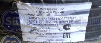
Nowadays it is convenient to make an air connection using a self-supporting insulated wire (SIP). The minimum cross-section of an aluminum core is 16 mm2, which is sufficient for a private home.
The SIP is attached to the supports and the wall of the house using anchor brackets with clamps. The connection to the main overhead line and the input cable to the electrical panel of the house is made with branch piercing clamps. The cable is taken with non-combustible insulation (VVGng) and passed through a metal pipe inserted into the wall.
Cable color marking
This is one of the simplest methods. To determine what phase and zero are by color, you need to clearly know which shades correspond to what. You can use information about the standards adopted in the country.
It's no secret that each wire has an individual color. Therefore, recognizing zero should not be a particular problem. The knowledge gained will allow you to easily cope with the installation of a lighting fixture or installation of an outlet. This method is especially relevant for new buildings. After all, there, as a rule, wires are laid by experienced specialists who strictly comply with norms and standards. The IEC 60446 standard, adopted on the territory of the Russian Federation in 2004, strictly regulates the separation of phase, grounding and zero by color.
It is worth considering that:
- if the wire has a blue or blue-white tint, we can safely say that this is a working zero
- the protective zero is represented by cables in a yellow-green sheath
- other colors are characteristic of the phase. It can be red, brown, white or black. Other options are also possible.
This designation is successfully used in most cases. But if the wiring is old, or there are doubts about the professionalism of electricians, it is more advisable to use additional methods.
Single-phase two-wire network 220V
This type of network includes an outdated type of wiring, where aluminum wires in a single white braid, popularly known as “noodles,” are used as cores. One core of the electrical wire is a phase conductor, the second core is a neutral conductor. A single-phase two-wire network is used for ordinary household needs: simple sockets and switches.
The problem when installing single-color wiring is that it is difficult to determine the phase and neutral wires. The presence of additional measuring equipment will help to cope with the task; you can use a multimeter or a special screwdriver with an indicator, a probe, a tester, or a “continuity tester”.
The design of a single-phase two-wire network is permitted by GOST for premises with a small load on the electrical network and low safety requirements. In such cases, two single-core wires or one two-core wire with wires of different colors are used.
When using a solid wire, one core is brown, the other blue or cyan. According to generally accepted markings, the brown conductor is a phase, and the blue conductor is a neutral conductor; it is strictly not recommended to violate this order. In practice, there are phase wires in colors other than brown: black, gray, red, turquoise, white, pink, orange, but not blue.
The use of two independent single-core wires also requires marking. You can use a wire colored along the entire length, for example, blue for zero, red for phase. It is permissible to mark wires of the same color with electrical tape or heat-shrinkable tubing of different colors, placing the marking on both ends of each wire.
The use of a tube does not involve wrapping the ends, but putting it on the wire and exposing it to hot air in order to fix the heat shrink on the wire. For home use, you can use any colors of marking materials that are accessible and understandable to the wiring installer.
Phase and zero: their meaning in the power supply network
Electricity is supplied to consumer sockets from substations, which reduce the incoming voltage to 380 V. The secondary winding of such a transformer has a “star” connection - its three contacts are connected to each other at the “0” point, the remaining three outputs go to the “A” / “B” terminals "/"WITH".
The wires connected at point “0” are connected to “ground”. At the same point, the conductor is divided into “zero” (indicated in blue) and a protective “PE” cable (yellow-green line).
This model of wiring is used in all houses currently being built. It is called the “TN-S” system. According to this diagram, three phase cables and two indicated zeros are suitable for the distribution equipment of the house.
In houses, enterprises and buildings of old construction there is often no “PE” conductor and therefore the circuit turns out not to be five-wire, but four (it is designated as “TN-C”).
All electrical wires from the substations are connected to the panel, forming a three-phase system. Then there is a division into separate entrances. Each of the entrance apartments is supplied with only one phase voltage - 220 V (wires “O” / “A”) and a protective “PE” cable.
With this scheme, the entire load on the power supply system is distributed evenly, since on each floor of the house specific panels are wired and connected to a specific 220 V power line.
The supply voltage circuit is a “star”, which exactly repeats all the vector characteristics of the supply substation. When there are no consumers in the sockets, no current flows in this circuit.
This connection scheme has been worked out for years. It confirmed its right to use by being recognized as the optimal of all existing ones. However, in it, as in any device, mechanism or device, all kinds of breakdowns and malfunctions may periodically appear. As a rule, they are associated with poor quality electrical connections or complete cable breaks in some places in the circuit.
What happens in zero and phase when a wire breaks.
Line breaks quite often occur due to the fault of the craftsmen - they forget to connect a phase or zero. Such breakdowns are quite common. Also, quite often the process of zero burnout on the access panel occurs, for example, due to high load in the system.
If a break occurs in any part of the chain, the entire chain stops functioning, because it opens. In such situations, it does not matter at all which wire is damaged - phase or neutral. The same thing happens when there is a break between the distribution board of a high-rise building and the panel in the entrance. With such a gust, all consumers who were connected to this panel will be without electricity.
All the situations that we tried to describe above occur. They may seem complicated, but they pose no danger to humanity. After all, the break occurred in only one wire, so it is not at all dangerous.
A very alarming situation is when the contact between the ground loop at the substation and the middle point, to which all the voltage of the in-house panel is supplied, is lost.
It is in this embodiment that the electric current moves along the contours AB, BC, CA. The total voltage of these circuits is 380V. It is for this reason that a rather dangerous situation arises - one panel may have no voltage at all, because the owner will turn off all electrical appliances, and a very high voltage level will form on the other, about 380V. This can contribute to the failure of many devices, because they require a voltage of 220V.
Naturally, this situation can be avoided. There is a lot of inexpensive/expensive equipment that will protect your equipment from power surges. Such equipment also includes a voltage stabilizer. There are the following types of stabilizers:
- Single phase;
- Three-phase.
Differences between the voltages under consideration
Single phase:
- It is supplied to connected devices via one single wire . The calculation and design of wiring diagrams is greatly simplified.
- Has only one nominal value.
- It cannot ensure the efficient operation of powerful units and machines (tens of kilowatts or more) due to the power supply through one channel.
- The occurrence of emergency situations (failure of equipment, fire, etc.) due to its excessively large value is determined mainly by external factors (transformer accident, lightning strike, etc.).
- Simpler and cheaper equipment is required to ensure safe operation in case of overloads.
- Intended primarily for domestic use with relatively low maximum power consumption levels.
- If the neutral wire breaks, electrical appliances will simply stop functioning due to the opening of the electrical circuit . It should be remembered that the entire network wiring will remain under operating voltage, and in the case of grounding electrical appliances to the operating zero, their housings will too.
- A greater drop in its value when something is connected. The reason is that all consumers “hang” on the same power line.
Three-phase:
- It is supplied to consumers via 3 wires . This complicates the development of plans for connecting them to electrical appliance connection points.
- May have two nominal values , depending on the connection diagram. This significantly expands the range of connected devices.
- Makes it possible to connect more powerful devices due to the presence of 3 power lines.
- Creates significantly greater risks in the event of a break in the neutral wire, which can lead to phase imbalance. In this case, the phase to which many consumers are connected will be overloaded and the voltage in it will drop, and in less loaded phases it will increase (possibly by tens of percent). This may lead to partial or complete failure of electrical appliances and/or fires.
- To ensure safe operation of connected devices more complex equipment to protect against emergency situations.
- Its significant increase due to an accident at a substation will most likely not lead to failure of the end user's electrical appliances due to the presence of additional protective equipment (see points 4 and 5).
- It is mainly used to power industrial equipment or distribution panels in apartment buildings.
- A smaller drop in its value on each wire due to the distribution of consumers across 3 supply branches .
Household electrical wiring device
A standard electrical wiring diagram contains the following elements:
- multi-tariff electricity meter;
- automatic switch with a rated current of 25 A;
- a shutdown mechanism that protects against short circuits and network overloads;
- differential circuit breaker with an operating threshold of 30 mA (leakage current), it protects sockets;
- cabinet for installation with busbars (neutral and grounding) and boards for installing switches;
- several lighting machines with a rated current of 10 A;
- cables with distribution boxes leading to sockets and devices that illuminate the premises.
Often apartment owners are interested in whether a phase is plus or minus, and what is the difference between zero and ground. Since the electrical phase has a variable potential, its indicator in the phase wire becomes either positive or negative. Therefore, it would be incorrect to say that phase is a minus (or a plus) - these concepts lie on different planes.
Now let's talk about how zero differs from ground. The difference is that current passes through the neutral wire and is opened by automatic devices (for example, the input wire). To ground in an apartment building, you need to connect to a conductor located in the riser, designed specifically for this purpose. It is strictly prohibited to use any other place, including the panel housing, for grounding - this can cause serious problems for the health of residents.
Single-phase and three-phase alternating current. Definitions
Alternating current is a current whose change in value and direction is repeated periodically at regular intervals.
Electric current, the strength of which varies sinusoidally in time and changes its sign (direction) twice over a period of time, is called alternating current.
Alternating current can be single-phase or three-phase. Single-phase current is transmitted through two wires (phase and zero). To transmit three-phase current, three wires are required (one wire for each phase).
Three sinusoidal (alternating) voltages of the same frequency and amplitude, shifted in phase by 120 degrees, form a three-phase network.
Three-phase networks have become widespread: three-phase power supply saves wires; three-phase generators, electric motors and transformers are cheaper, lighter, and more economical.
The widespread use of alternating current in various fields of technology is explained by the ease of its production and conversion, as well as the simplicity of the design of alternating current generators and motors, the reliability of their operation and ease of operation. Modern energy requires the transfer of energy over long distances using electric current. Such transmission requires the ability to convert current easily and efficiently. Such a conversion is possible only with the use of transformers operating only on alternating current. A great incentive for the development of alternating current electrical devices is the possibility of obtaining high-power energy sources.
Modern thermal and hydroelectric generators have a capacity of 100 – 1500 MW. The simplest and cheapest electric motors include asynchronous AC motors, which do not have moving electric contacts. Transmitting alternating current over long distances requires wires of smaller cross-section than direct current.
Basic parameters of alternating current. Period, frequency
The main parameters of alternating current are the following quantities:
- instantaneous values of current and voltage - their values at any time;
- amplitude values of current and voltage – maximum values of instantaneous quantities;
- effective values of current and voltage;
- period - a period of time during which the current makes a complete oscillation and takes on the same instantaneous value in magnitude and sign; the period is expressed in seconds (s), milliseconds (ms) and microseconds (μs).
- frequency is the reciprocal of the period f = 1/T where T is the period;
The unit of frequency is hertz (Hz), f = 1/s = 1Hz.
Frequency is also measured in kilohertz (kHz), megahertz (MHz) and gigahertz (GHz).
The industrial frequency of the power grid in Russia and in most countries of the world is 50 Hz (in the USA - 60 Hz). The reason for this choice is simple: lowering the frequency is unacceptable, since already at a current frequency of 40 Hz incandescent lamps blink noticeably to the eye; An increase in frequency is undesirable, since an increased frequency negatively affects the transmission of energy through wires and the operation of many electrical devices.
DC network
A DC network differs from an AC network in that it contains two conductors: plus and minus. The core of the positive conductor is marked in red, and the core of the negative conductor is marked in blue.
The practice of color separation of wires is familiar to professionals and amateurs; it is actively used in electrical engineering, but still you should not blindly trust the markings. Backing up with a measuring device is a thoughtful and balanced move when installing electrical networks; you should not neglect it.
If you are an electrician, we would appreciate your feedback on this article. Please write your comment below.
Two-phase electrical networks
were used in the early 20th century in AC electrical distribution networks. They used two circuits, the voltages in which were shifted in phase relative to each other by 90 degrees. Typically, 4 lines were used in the circuits - two for each phase. Less commonly used was one common wire, which had a larger diameter than the other two wires. Some of the earliest two-phase generators had two full rotors with windings physically rotated 90 degrees.
The first ideas for using two-phase current to create torque were expressed by Dominic Arago in 1827. The practical application was described by Nikola Tesla in his patents from 1888, around the same time he developed the design of a corresponding electric motor. These patents were then sold to the Westinghouse company, which began developing two-phase networks in the United States. Later, these networks were supplanted by three-phase networks, the theory of which was developed by the Russian engineer Mikhail Osipovich Dolivo-Dobrovolsky, who worked in Germany at the AEG company. However, due to the fact that Tesla's patents contained general ideas for the use of polyphase circuits, the Westinghouse company was able to hold back their development for some time through patent litigation.
The advantage of two-phase networks was that they allowed simple, soft starting of electric motors. In the early days of electrical engineering, these networks with two separate phases were easier to analyze and design. At that time, the method of symmetrical components had not yet been created (it was invented in 1918), which subsequently gave engineers convenient mathematical tools for analyzing asymmetrical load modes of multiphase electrical systems.
Two-phase circuits typically use two separate pairs of current-carrying conductors. Three conductors can be used, however, the vector sum of phase currents flows through the common wire, and therefore the common wire must have a larger diameter. In contrast, in three-phase networks with a symmetrical load, the vector sum of the phase currents is zero, and therefore in these networks it is possible to use three lines of the same diameter. For electrical distribution networks, the requirement of three conductor lines is better than the requirement of four, since this results in significant savings in the cost of conductor lines and in installation costs.
Two-phase electrical networks
were used at the beginning of the 20th century in AC electrical distribution networks. They used two circuits, the voltages in which were shifted in phase relative to each other by (90 electrical degrees). Typically, four lines were used in the circuits - two for each phase. Less commonly used was one common wire, which had a larger diameter than the other two wires. Some of the earliest two-phase generators had two full rotors with windings physically rotated 90 degrees.
The first ideas for using two-phase current to create torque were expressed by Dominic Arago in 1827. The practical application was described by Nikola Tesla in his patents from 1888, around the same time he developed the design of a two-phase electric motor. These patents were then sold to the Westinghouse company, which began developing two-phase networks in the United States. Later, these networks were supplanted by three-phase networks, the theory of which was developed by the Russian engineer Mikhail Osipovich Dolivo-Dobrovolsky, who worked in Germany at the AEG company. However, due to the fact that Tesla's patents contained general ideas for the use of polyphase circuits, the Westinghouse company was able to hold back their development for some time through patent litigation.
The advantage of two-phase networks was that they allowed simple, soft starting of electric motors. In the early days of electrical engineering, these networks with two separate phases were easier to analyze and design. At that time, the method of symmetrical components had not yet been created (it was invented in 1918), which subsequently gave engineers convenient mathematical tools for analyzing asymmetrical load modes of multiphase electrical systems.
Scott transformer circuit
Two-phase circuits typically use two separate pairs of current-carrying conductors. Three conductors can be used, however, the vector sum of phase currents flows through the common wire, and therefore the common wire must have a larger diameter. In contrast, in three-phase networks with a symmetrical load, the vector sum of the phase currents is zero, and therefore in these networks it is possible to use three lines of the same diameter. For electrical distribution networks, the requirement of three conductor lines is better than the requirement of four, since this results in significant savings in the cost of conductor lines and in installation costs.
Two-phase voltage can be obtained from a three-phase source by connecting single-phase transformers according to the so-called Scott circuit. A symmetrical load in such a three-phase system is exactly equivalent to a symmetrical three-phase load.
In some countries (for example, Japan), the Scott circuit is used to power railways electrified using a single-phase alternating current system of industrial frequency. In this case, only two phases alternate in the contact network, and not three. On double-track roads, tracks of different directions can each be powered throughout its entire length from its own phase of a two-phase network, which makes it possible to get rid of the alternation of phases along the train and the installation of neutral inserts (although this complicates the operation of stations). In Russia, such a system has not become widespread.
Single-phase alternating current and its parameters
Alternating current has not found practical use for a long time. This was due to the fact that the first electrical energy generators produced direct current, which fully satisfied the technological processes of electrochemistry, and direct current motors have good control characteristics.
However, as production developed, direct current became less and less suitable for the increasing requirements for economical power supply. Alternating current made it possible to effectively split electrical energy and change the voltage using transformers. It became possible to produce electricity at large power plants with its subsequent economical distribution to consumers, and the radius of power supply increased.
Currently, the central production and distribution of electrical energy is carried out mainly on alternating current. Circuits with changing - alternating - currents have a number of features compared to direct current circuits. Alternating currents and voltages cause alternating electric and magnetic fields. As a result of changes in these fields in circuits, the phenomena of self-induction and mutual induction arise, which have the most significant impact on the processes occurring in the circuits, complicating their analysis.
Alternating current (voltage, emf, etc.) is a current (voltage, emf, etc.) that varies over time. Currents whose values are repeated at regular intervals in the same sequence are called periodic, and the shortest period of time through which these repetitions are observed is called period T.
Basic parameters of single-phase alternating current circuits.
Single-phase industrial frequency alternating current has 50 oscillation periods per second, or 50 Hz. It is used to power small fans, household appliances, power tools, electric welding and to power most lighting devices. AC frequency, Hz:
f= 1/T = np/60,
where n is the generator rotation frequency, minˉ 1; p—number of generator pole pairs.
Single phase AC power:
active, W, Ra = IUcosφ;
reactive, var, Q = IUsinφ;
apparent, V A, S = IU =
If only active resistance is included in the single-phase alternating current circuit (for example, heating elements or electric lamps), then the value of current and power at each moment of time is determined by Ohm’s law:
I=U/R; Pa = IU = I²R=U²/R.
Power factor in a circuit with an inductive load
Cosφ= Pa/IU= Pa/S.
Basic concepts and quantities characterizing electrical circuits
Concepts:
An electrical circuit is a set of devices intended for the passage of electric current, the electromagnetic processes in which can be described using the concepts of voltage and current. In the general case, an electrical circuit consists of sources and receivers of electrical energy and intermediate links (wires, devices) connecting sources with receivers.
Sources of electrical energy are devices (galvanic cells, batteries, thermoelements, generators) in which the process of converting chemical, molecular-kinetic, thermal, mechanical or other types of energy into electrical energy occurs.
Receivers of electrical energy (load) are devices (electric lamps, electric heating devices, electric motors, resistors, capacitors, inductive coils) in which electrical energy is converted into light, heat, mechanical, etc.
Quantities:
Electric current and voltage are the main quantities characterizing the state of electrical circuits.
Electric current in conductors represents the phenomenon of ordered movement of electric charges. The term “current” also refers to the intensity or strength of current, measured by the amount of electric charge q passing through the cross-section of a conductor per unit time:
Therefore, current represents the rate of change of charge over time. In SI, charge is expressed in coulombs (C), time in seconds (s), and current in amperes (A).
Current as a ratio of two scalar quantities is a scalar algebraic quantity, the sign of which depends on the direction of movement of charges of the same sign, namely the conventionally accepted positive charge. To unambiguously determine the sign of the current in the positive direction, it is enough to arbitrarily select one of two possible directions, which is marked with an arrow.
If the movement of a positive charge occurs in the direction of the arrow, and the movement of a negative charge occurs towards it, then the current is positive. When the direction of movement of charges changes to the opposite, the current will be negative.
It is possible to uniquely set the current in the form of a certain function of time only after specifying the selected positive direction of the current. Therefore, before starting the analysis, it is necessary to note the positive directions of currents in all sections of the circuit, the choice of which can be arbitrary.
The passage of electric current or the transfer of charges in a circuit involves the conversion or consumption of energy. To determine the energy spent on moving a charge between the two points of the conductor under consideration, a new quantity is introduced—voltage.
Voltage is the amount of energy expended to move a unit of charge from one point to another:
, where w is energy.
When measuring energy in joules (J) and charge in coulombs (C), voltage is expressed in volts (V).
Stress as a ratio of two scalar quantities is also a scalar algebraic quantity. To unambiguously determine the sign of the voltage between the two terminals of the section of the circuit under consideration, one of the terminals is conventionally assigned a positive polarity, which is marked either with an arrow directed from the terminal or with the signs “+”, “-”
The voltage is positive if its polarity matches the selected one; this means that the potential of the terminal with the “+” sign, from which the arrow comes out, is higher than the potential of the second terminal.
Before starting the analysis, the selected positive voltage polarities must be indicated - only under this condition is it possible to unambiguously determine the voltages.
Although the conditionally positive voltage polarity can be chosen arbitrarily, it is usually convenient to choose it consistent with the selected positive current direction when the arrows for current and voltage coincide or the “+” sign of voltage polarity is at the tail of the arrow indicating the positive direction of current. With a consistent choice of polarity, it is obviously sufficient to limit yourself to indicating only one arrow in the positive direction of the current.
If there is a need to select a positive voltage polarity that is not consistent with the positive direction of the current, then you have to indicate two counter-directed arrows: for current and for voltage. This is not very convenient. Therefore, to denote conditionally positive polarity, we will use the signs “+.”, “-” at the terminals of a section of the circuit.
Power in an electrical circuit, equal to the product of voltage and current, is also an algebraic quantity. Its sign is determined by the signs of voltage and current: if these signs coincide, the power is positive, which corresponds to energy consumption in the section of the circuit under consideration; when the signs of voltage and current do not match, the power is negative, which means it is released from a section of the circuit (such a section is a source of energy).
Receiving alternating current
Current generation is based on the phenomenon of electromagnetic induction, which was discovered by Michael Faraday. Its essence is this: in a conductor located in a magnetic field with changing characteristics, an electromotive force (EMF) arises.
The magnetic field parameters mean:
- field line density;
- the angle of their direction relative to the conductor.
There are several ways to ensure changes in magnetic field parameters:
- move (rotate) the conductor in the field of a permanent magnet;
- rotate a permanent magnet around a conductor;
- place a current-carrying element in the field of an electromagnet (a wire wound in the form of a coil) with alternating current flowing through it.
The first two methods are used in electric generators, the last one is used in current transformers. Moving a magnet or conductor requires mechanical energy. It is converted by the generator into electric power. The direction of the EMF is determined by the right hand rule.
In this position, when the field lines enter the palm, and the thumb moved to the side coincides with the vector of movement of the conductor, the other fingers point to the direction of the EMF. The simplest alternating current generator is a wire frame rotating between permanent magnets and connected to an electrical circuit.
The contact between the moving frame and the stationary conductive elements of the chain is sliding: rings are attached to the ends of the frame, and graphite brushes (have a low coefficient of friction) pressed against these rings are attached to the ends of the chain.
The rotating part of a generator or electric motor, in our example this is a frame, is called a rotor. Fixed - stator.
The EMF induced in the frame is determined by the formula: E = B*S*ω*sinα, where B is the magnetic induction, S is the area of the frame, ω is the angular frequency, A is the angle of rotation of the frame.
Only the angle α changes, therefore, the graph of the EMF changes has the form of a sinusoid. Since the current, in accordance with Ohm's law, is equal to the ratio of the emf to the load resistance (I = E/R), it is also sinusoidal.
The sinusoidality of the EMF and current variables means that they periodically change not only the magnitude, but also the direction to the opposite.
Schematic diagrams of alternating current generators
What does electrical voltage indicate?
From a school physics course we know that an electric field is a special type of matter that arises around electric charges. It can be observed by creating a charge, for example, through friction - after combing, the comb begins to attract small pieces of paper. If charged particles move along a conductor, then a current , and a magnetic field , with the help of which useful work can be done. This phenomenon underlies the operation of electric motors. And vice versa - if you move a magnet next to a conductor (or inside a conducting coil), then an electric current will arise in the conductor - electric generators are based on this phenomenon.
It is also possible to create the movement of charged particles along a conductor using special chemical reactions - chemical current sources - batteries and accumulators - .
The “force” with which charges will move along a conductor is called electrical voltage , the unit of measurement is volts. And the number of these charges moving along a conductor is an electric current , the unit of measurement is ampere .
A regular battery is enough to light a flashlight, but to do a lot of work you need a much higher voltage, which is created by special large generators.
Disadvantages of AC
The most important disadvantage of alternating current is the presence of reactive power. As is known, a capacitor and an inductor exhibit their reactive properties only in alternating current circuits. Simply put, the coil and capacitor create reactance to AC current, but do not consume it. As a result of this, of the total power supplied by the alternator, part of the power is not spent on performing useful work, but only circulates uselessly between the generator and the load. This power is called reactive power and is harmful. Therefore, they try to minimize it.
However, most loads - motors, transformers and the wires themselves - are inductive elements. And the greater the inductance, the greater the proportion of reactive power from the total and this must be dealt with.
The second main disadvantage of alternating current is that it does not flow across the entire cross-section of the conductor, but is displaced closer to its surface. As a result, the area through which electric current flows decreases, which in turn leads to an increase in the resistance of the conductor and an increase in power losses in it.
The higher the frequency, the more current is displaced to the surface of the conductor and, ultimately, the higher the power loss.
Electrification of railways using alternating current
The Russian AC passenger electric locomotive EP1P is produced at the Novocherkassk Electric Locomotive Plant.
In Russia and the republics of the former USSR, about half of all railways are electrified using single-phase alternating current with a frequency of 50 Hz. A voltage of ~ 25 kV (usually up to 27.5 kV, taking into account losses) is supplied to the contact wire, the second (return) wire is the rails. Electrification is also carried out according to the 2 × 25 kV system (two twenty-five kilovolts each), when a voltage of ~ 50 kV is applied to a separate supply wire (usually up to 55 kV, taking into account losses), and half the voltage of 50 kV is applied to the contact wire from autotransformers (i.e. 25 kV). Electric locomotives and AC electric trains do not require alteration when operating on 2 × 25 kV sections.
A policy is being pursued to further expand the AC traction range both through newly electrified sections and through the transfer of some lines from direct current to alternating current. Transferred to 1990s - 2000s:
on the East Siberian Railway: section Slyudyanka - Irkutsk - Zima; - on the Oktyabrskaya Railway: section Loukhi - Murmansk; — on the Volga Railway: Saratov and Volgograd railway junctions; - on the North Caucasus Railway: sections Mineralnye Vody - Kislovodsk and Beshtau - Zheleznovodsk.
It should be noted that dual-system electric locomotives are also produced that can operate on both alternating and direct current (see VL61D, VL82 and VL82M, EP10, EP20).
Generation and transformation
The principle of generating electricity is simple. If a magnetic field rotates along a stationary set of coils of turns of a conductor or, conversely, a coil rotates around a stationary magnetic field, then due to the phenomenon of electromagnetic induction, a potential difference arises at the ends of the windings. With each change in the angle of rotation resulting from the described circular motion, the output voltage will also change in both magnitude and direction.
The described conditional generator at a constant angular speed of rotation of the shaft produces a sinusoidal AC with a waveform that is no different from that supplied in a household network. Real generators are much more complex, but operate on the same principles of electromagnetic induction.
These same laws help not only in the production of AC, but also in its transmission and distribution. Voltage conversion by power companies cannot be accomplished without electrical machines called transformers.
This is why Tesla's invention was so important to the revolution in electricity transportation.
Any transformer consists of the following elements:
- primary and secondary windings;
- core.
The word “primary” is used for the winding to which the electrical voltage that needs transformation is applied. The induced voltage on the secondary coil is always equal to that applied on the primary, multiplied by the ratio of turns of the secondary to the primary. The transformer allows you to change the voltage step by step.
General information about three-phase voltage
4 wires are supplied to the consumer - 3 phase and 1 neutral . The 3rd ones transmit alternating current, the amplitude parameters of which are shifted in each phase by 1/3 of a cycle relative to the other 2. In household networks, the voltage on each phase relative to zero is 220 volts (phase), and between phases - 380 volts (linear). The main purpose of the neutral wire is to equalize phase voltages when the load on them is uneven.
Advantages:
- The transmitted power depends on the cross-sectional area of the cable.
- Possibility of connecting industrial type equipment.
- Switching from one phase to another in case of an emergency.
- Greater economic efficiency of electricity consumption.
Flaws:
- Higher equipment costs.
- Presence of higher voltage (linear).
- Limitation of the maximum load power on one phase (relative to the maximum on all phases combined).
Options
In the characteristics of alternating current, there are basic and additional parameters.
- frequency;
- period;
- amplitude;
- effective value.
Additional:
- angular frequency;
- phase;
- instantaneous value.
Let's look at them in detail.
Frequency
The letter designation is f, the unit of measurement is hertz (Hz). Indicates the number of complete cycles of current oscillations per second.
The frequency of the alternating current at the output of the simplest generator is determined by the speed of its rotor. In the power supply system of Russia and other countries of the former USSR, a current with a frequency of 50 Hz is used.
Change curves of sinusoidal alternating current at different frequencies
In some cases, the frequency is increased by converting the current. For example, in inverter welding machines and pulse power supplies - up to 20 - 80 kHz. At this frequency, the dimensions of the transformer and losses in it are significantly reduced. In some devices the frequency is increased to several MHz.
Period
Designation - "T", unit of measurement - second. Period is the duration of a complete cycle of current oscillations. This parameter is related to frequency by the following relationship:
T = 1/f.
Accordingly, in the electrical network the current period is 1/50 = 0.02 s = 20 ms.
Amplitude
The maximum value of current or EMF corresponds to the top of the half-wave. Denoted, respectively, Im and Um. During the period, these values reach amplitude values twice - with a positive and negative sign.
Effective value
This is a direct current equivalent to a given alternating current in terms of work performed. Constantly changing alternating current is inconvenient to use in calculations, so it is replaced by the effective value. Denoted by the letters I and U.
For sinusoidal current and EMF is determined by the formula:
I = 2^(-1/2) * Im = (1/1.414) * Im = 0.707 Im;
U = 2^(-1/2) * Um = 0.707 Um;
Voltage 220 V in a household electrical network is the effective value. The amplitude is 311 V. Similarly, if they say that the load consumes a current of 5A, they mean the effective value. The current amplitude is 7.07 A.
Angular frequency
Indicates the rate of change of angle α in the EMF calculation formula. Corresponds to the angular frequency of rotation of the rotor. Since during one period the angle a changes by 2π at a standard frequency f = 50 Hz, the angular frequency will be: ω = 2π * 50 = 100 π.
Phase - the nature of the change in angle α relative to the time reference point. Currents and EMF can be in phase or have a shift. The latter is measured in radians, degrees or fractions of a period. When the phase shifts by π (1/2 period), the quantities are said to be out of phase.
AC current and voltage phase shift
Advantages of three-phase connection
Let us note the main advantages of a three-phase network.
| Advantages | Description |
| Universal use | Both single-phase loads (220 V) and electrical installations operating on line voltage (380 V) - machine tools, welding machines and other specialized high-power electrical equipment - can be connected to a three-phase network. |
| Connecting a large number of electrical appliances | Higher output power – from 15 kW, which allows you to connect a large number of electrical appliances. |
| Rational phase distribution | For a large household, introducing a three-phase network into a private house is more rational. Since there is a choice of distributing 3 phases between rooms or consumers in the house. For example, you can use one phase for home electrical wiring, a second for powerful household appliances, and a third for utility rooms. |