Very often in domestic conditions there is a need to use equipment where the drive is a three-phase asynchronous motor. In this regard, the problem arises of how to make 380 volts from 220. Most often in practice, inverters are used - special devices for converting voltage. The converters regulate voltage consumption to an optimal level and can change the drive frequency.
Advantages of frequency converter
Universal power frequency converters innovert idd from single-phase current 220 volts to three-phase 380 volts are made on the basis of a simple three-phase electric motor and have a number of advantages:
- Can produce three-phase current 380 volts of voltage.
- An asynchronous motor does not lose power.
- It is used for different types of motors with any characteristics (limited only by network, power no more than 7 kilowatts).
- It has a simple design. People with secondary education can easily do it in a couple of hours. You will need a three-phase asynchronous motor with a power of 4 kilowatts, a capacity of 50 microfarads, pieces of wire, three phases. The electric motor does not need to be rebuilt.
- Power consumption from the network is small. A 4 kW engine takes about 200 watts from the network at idle.
How to make a converter from 220v to 380 yourself using a transformer
An energy converter is one of the most common devices that can be used by both beginners and experienced craftsmen. Using transformers, you can achieve any voltage within the permissible service life of the device, including 380 Volts. As for the use of a capacitor for energy storage, its necessity always remains at the discretion of the consumer.
In order to ensure stable power supply on three phases, a special three-phase transformer should be used. The main function of the unit, in addition to changing the voltage, is to convert single-phase current into three-phase. Similar devices are available in most electrical stores.
The voltage converter coils are fastened with a triangular clamp. Voltage will be supplied to both primary coils directly, and to the latter using a storage device. The capacitor should be selected based on 7 uF, which falls on every 100 watts of power.
Operation process without capacitor
Attention! It is important that the minimum factory power of the device is at least 400 watts. In addition, it should be noted that such devices are prohibited from being put into operating mode without load.
If this happens, then the required voltage will be achieved, but the power of the electric motor will be reduced, and the efficiency, in turn, will begin to sharply approach zero.
How to connect a three-phase motor to a 220 V network
The use of a three-pole AD in a single-phase electrical network is of interest to many owners of private houses. The units are increasingly in demand in households. They are quite simple in design and easy to use. However, in terms of connecting the motor to a single-phase network, not everything is so simple.
The pulsating field of a single-phase current is not capable of causing the rotor of an electric motor to rotate - such a current must be converted into multiphase and then only supplied to the unit.
You should not pay attention to rationalization proposals using LATRs and other home-made structures. We are not involved in the field of prohibitive NANO technology and science fiction; we cannot count on fees for the support of “Nobel laureates”
Today, there are two sensible ways to convert single-phase current into multiphase - this is connecting the unit through:
- phase shifting capacitor;
- a frequency converter.
Let's look at them one by one.
- Phase shift using capacitors
In three-phase circuits, creating a rotating magnetic field is not a problem; during energy generation, an EMF is induced in the stator windings due to the rotation of the magnetized rotor. Some manage to resort to simple “tricks”. Various schemes are used, for the compilers of which the main question is to ensure the operation of electrical equipment without loss of power. For example, there is a method of shifting the phases in the windings relative to each other.
It is enough to connect a capacitor in parallel with one of the windings, first selecting the device rating in such a way as to ensure the necessary phase shift. This option is not bad if you follow the old rule: the fewer and simpler the parts, the more reliable the system as a whole. The capacitor, of course, is a relatively cheap thing, it can be installed in a minute, but it requires special skills. But the second method with a converter, although a little expensive, pays off in convenience. Agree, this is a very important factor.
- Frequency generators operating from a single-phase network
The frequency in our network is constant and equal to 50 Hz. The frequency converter is used to convert single-phase alternating current of 50 Hz into three-phase, with a frequency from 1 to 800 Hz. The entire process technology comes down to controlling the rotation speed of an asynchronous electric motor. Connecting the inverter means choosing the correct cable cross-section, wire types, and additional equipment. Do not think that by opening a page in the instructions, the essence will immediately become clear to you.
You may not even achieve the result by connecting the wires according to the diagram if you do not pay attention to some nuances. For what exactly?
Do-it-yourself converter from one to three phases.
Since the three-pole motor needs to be powered through a state of emergency from a single-phase network, two cables are needed: to the frequency converter, a two-wire one (up to 50 m, you can only use an unshielded cable, shielded - up to 15 m), from the frequency converter to the motor, only a three-wire cable. One of the wires is grounding, the rest are phase. The cross section is selected according to the technical data sheet for the frequency generator. The required voltage in the wires is obtained from the current and resistance (according to the cross-section) of the cable using the familiar formula: U = R*I. Calculation data should be taken according to the PUE.
It is recommended to buy a frequency generator with a double margin, at least 2 kV. Its nominal value is designed only for the power of the machine, which means that at best it will turn off due to heat, at worst it will smoke. All of them are assembled according to the same circuit, using two thyristors controlled by a multivibrator. The scheme is simple. It is better to choose a simple and more powerful one. Buy where there is a choice and always with a guarantee.
Methods for obtaining 380 Volts from 220
Let's look at the main ways to convert 220 volts into full three-phase current, 380 V:
- using an electronic voltage converter;
- by using a transformer;
- using three phases;
- using a three-phase motor as a generator;
- using a capacitor circuit.
Voltage transformer
The easiest and most reliable way to convert 220 V to 380 is to buy an electronic voltage converter. (see Fig. 2). This device is often called an inverter. The gadget is easy to operate and generates high-quality three-phase current. True, the power of inverters is not very large, but, as a rule, it is enough for most three-phase household appliances.
Rice. 2. Voltage converter
The converter is also good because it has a built-in overload and short circuit protection function. This means that the electric motor will not overheat and will not fail as a result of a short circuit.
High quality current is achieved thanks to the operating principle of the device. The inverter first rectifies single-phase alternating current and then generates three-phase voltage at a given frequency and with a standard phase shift. In this case, the number of phases can be more than 3 (with a corresponding shift angle).
Using a transformer
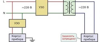
Using a step-up transformer, you can get any voltage, including 380 V. However, if you are interested in three-phase voltage, then you need a special three-phase transformer. converting single-phase current into three-phase. Such transformers are commercially available.
The transformer windings are connected in star or delta. Single-phase network voltage is supplied to two primary windings directly, and to the third through a capacitor. In this case, the capacitor capacity is selected at the rate of 7 μF for every 100 W of power.
Please note that the rated voltage of the capacitor should not be lower than 400 V. Such a device cannot be turned on without a load.
Although we will obtain the necessary 380 V in this way, there will still be a decrease in the power of the electric motor (if you plan to connect it to a transformer). Accordingly, the engine efficiency will also drop.
Using 3 phases
If you live in an apartment building, then 3 phases are already connected to it, which, in order to optimally distribute the loads, are separated into individual apartments. On each floor there are distribution boards, from where you can bring the missing two phases into the apartment. But this will require permission.
If you wish, you can obtain permission from the energy supply company or coordinate with Energonadzor the installation of three-phase power in your apartment. In this case, you will need to install a three-phase electricity meter.
Using an electric motor
You probably know that the rotor of a conventional three-phase motor, after starting, continues to rotate after one phase is disconnected. It turns out that there is an EMF between the terminal of the disconnected winding and the activated terminals.
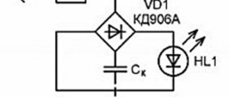
The phase shift between the stator windings depends only on their location. In a three-phase motor, these coils are located at an angle of 120º, which means they provide the same phase shift angle. This circumstance suggests that an asynchronous three-phase motor can be used to obtain 380 volts from a conventional single-phase network. A simple diagram for connecting an electric motor is shown in Figure 3. The capacitor in the diagram is needed only to start the engine. Once launched, you can disable it. We take the capacitor type MBGO, MBGP, MBGT or K42-4, the operating voltage of which must be at least 600 V. You can use the capacitor K42-19, with an operating voltage of at least 250 V.
For an example of connecting a phase-shifting capacitor, see Fig. 3.
Rice. 3. Connecting the starting capacitor
We select the parameters of the capacitor depending on the power of the motor. Note that the parameters of the phase-shifting capacitor do not affect the quality of the generated current. We connect the load to the stator windings according to the diagram shown in Fig. 4.
Rice. 4. Three-phase current from an electric motor
The rotor rotation speed is almost independent of the single-phase network voltage, so it can be considered constant. This means that the frequency of three-phase current at rated loads will not change.
It should be borne in mind that the power of a three-phase motor operating from a single-phase network decreases. Accordingly, the rated power of a three-phase load will be approximately one third lower than that stated in the electric motor’s passport.
Electric motor as generator
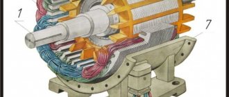
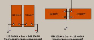
Another way to get 380 from 220 V is to create a motor-generator system. As a motor, you can take any electric motor operating from a 220 V network, and as a generator, you can take a modified three-phase asynchronous motor (see Fig. 5 for the installation diagram).
Let us immediately note that the effectiveness of such an installation is questionable, but it is possible to obtain the required voltage of 380 V in this way. In this circuit, it is necessary to ensure such a rotor speed that the generator produces current with a frequency of 50 Hz. To do this, it is necessary to rotate the shaft at an angular speed of 1500 rpm.
Rice. 5. Three-phase motor as generator
At home, you can use a single-phase motor from a washing machine or other household appliances as a drive. It is only important to ensure the required angular speed of rotation of the rotor.
Since the rotation of the shaft of electric motors operating, for example, in a washing machine is about 12 - 20 thousand rpm, it is necessary to use pulleys whose diameters have a ratio of 1 to 10. That is, to ensure rotation of the generator rotor at a speed of 1500 rpm min. you can take a pulley that is already mounted on an electric motor from a straightening machine, and put a pulley with a diameter 10 times larger on the shaft of a three-phase motor.
Is it possible to make 380V from 220V
At various industrial enterprises or in premises with special functionality, generators produce mainly three-phase current, which makes it possible to increase its voltage several hundred times when using special equipment. According to DEP installations, energy is supplied to consumers, but before that it must go to a power transformer, which will increase the voltage to 380 V. From the distribution substation, the energy will move to the consumer line.
Motor connection
In three phases, the current is transmitted in such a way that its particles move along perpendicular trajectories. Inside the conductor the voltage is 380 Volts, and between the phases - 220 Volts, which is a normal value for residential premises. Considering that the vast majority of apartments are electrified using a single-phase scheme, the two missing phases can be brought into the room from the nearest distribution board.
Attention! Today, there are many converters available on the market that can increase the power of electric current. But when working with them, you must adhere to certain safety rules.
Many ordinary people who have not studied the features of converting electric current are concerned with the question of how to get 220 volts from 380 volts and vice versa, what types of adapters should be used? The modern electrical engineering market offers a lot of devices for voltage conversion. Depending on the power of the connected equipment, each consumer can choose either a simple household inverter or a high-tech industrial installation.
You might be interested in this: Features of conductor resistance
Materials, equipment
Electrical wiring is made closed or open. The first, hidden in the wall, is protected from moisture and mechanical influences, but requires significant physical effort. The second one is laid “without noise and dust,” so the work goes very quickly. Plus - the ability to easily replace elements or modify the circuit.
More often, garage owners choose the second option. It is better for owners of premises in suburban areas to give preference to closed electrical wiring. All electrical equipment is protected using corrugated pipes and cable ducts. The latter are long and narrow plastic trays whose lids snap on.
Cable
For electrical wiring in the garage, choose the following types of cables:
Since, in addition to the cross-section, an important characteristic is the number of conductors, preference is given to VVG products having from 1 to 5 conductors. Their other advantages are a wide temperature range (from -50 to +50°), strength, and moisture resistance.
It is not recommended to use aluminum products: regardless of its cross-section, the cable may break, and in this case the wiring will have to be completely changed sooner or later. With an open installation method, you will need to calculate the number of corrugated pipes or cable ducts, fasteners necessary to fix the wiring.
Automatic protection devices
To prevent overcurrent and short circuits, circuit breakers are installed in the lines. To eliminate the possibility of electric shock to people, special devices are used - RCDs. When developing a wiring diagram for a garage, you must:
Replacement options
It is also possible to obtain a 380 V voltage source through the use of three phases from electrical power sources with a voltage of 220 V, however, in high-rise buildings this is recommended only with the consent of the energy supervision company. If it is possible to connect electrical equipment to a three-phase distribution panel, which is usually located in the entrance, a voltage converter is not needed - a three-phase extension cord is sufficient
Existing methods of converting single-phase current into three-phase, although effective, have some disadvantages:
- frequent loss of engine power;
- impossibility of obtaining three-phase current without interference;
- power limitations of frequency converters;
- the presence of types of electric motors that cannot be started using similar methods in a single-phase network;
- Power capacitors are not very convenient to use, since the system turns out to be large and poses a danger to the room.
It is possible to make such a device at home, but it is quite problematic and labor-intensive, so buying an inverter will be a much simpler and safer decision, given the wide selection of products in this segment.
Electrical wiring diagram in the garage: requirements, necessary devices and installation
For almost any car enthusiast, a garage is not only a convenient shelter for a vehicle, but also a frequently visited place. This parking lot often becomes a convenient workshop, utility room or warehouse for all sorts of “useful things”. Since the owner from time to time needs to recharge the battery or pump up a flat tire, it is extremely difficult to do without electricity in such a room. It is always required: for basic convenience, for working with various electrical tools. Since not the most “peaceful” substances (for example, fuels and lubricants, gasoline) are stored in the “home” for the car, the electrical wiring diagram in the garage must be thoughtful and completely safe.
Using a special inverter
Modern semiconductor devices make it possible to create high-frequency inverters. There are already many models of welding machines and mini-power plants with a capacity of several kilowatts or more. For such electronic circuits that have a built-in rectifier, it does not matter which output signals are generated. And with the highest quality. Therefore, the simplest option, albeit with a price of approximately $130/kW, is to purchase a special inverter converter.
One of the models of converter of single-phase voltage 220 V to three-phase voltage 380 V
There are many different models of single-phase to three-phase voltage converters on the market. Their price for the same power depends on:
- quality of the output voltage sinusoid;
- the presence of various protections (for example, against load loss in one of the phases, overload of input voltage, output current, over temperature);
- the possibility of smooth acceleration of an asynchronous engine;
- control the speed and direction of rotation of the electric motor shaft;
- remote control capabilities;
- sensor, filters, auxiliary units and accessories.
Which of the listed methods is optimal for the reader is determined by their comparison in specific conditions. The information provided is quite sufficient for this.
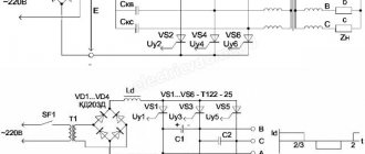
Three-phase inverter circuit
The voltage across the filter capacitors is approximately 430 V with no load and drops to 400 V with load. In the inverter, the transistors switch at a frequency of 5 kHz, because the FNA41560 chip is optimized for this frequency; the deadtime for the transistors is about 1.2 μs (see oscillograms).
The inverter has protection against high temperature (over 105 C), short circuit (from 5 A), high voltage on filter capacitors (460 V). Short circuit protection is automatically reset at the end of each PWM cycle (acts as a current limit). This can be changed in the PIC33FJ32MC102 P1FLTACON microcontroller register to hold mode. In this mode, the PWM generators are turned off and stopped until the problem is resolved. The frequency is controlled by a multi-turn potentiometer, with a resolution of 0.1 Hz. Adjustable frequency range from 1 Hz to 80 Hz. The useful range starts at 5 Hz. To generate the output signal, a VSM-spatial vector modulation algorithm was used (as it sounds!), which allows maximum use of the DC voltage supplied to the FNA41560 module.
Please remember that the circuit's power supply is not isolated from the mains and special precautions should be taken when using it. Lack of galvanic isolation is potentially life-threatening.
It is proposed to start assembling the device with soldering, and then launch the PFC part, solder the MC33262 integrated circuit, rectifier bridge, diode D11, transistor Q1 and inductor, filter capacitors C17 and C22, to which 470 kOhm resistors need to be soldered. The winding (3 coils) must be wound around the inductor, which will power the MC33262 chip. A cable from a computer network was used for winding. The end and beginning of the windings are important in terms of polarity and must be connected as indicated in the instructions for use.
The inverter power should be supplied through thermistors to limit the current flowing through diode D11, or use another solution to limit the inrush current. In this case, 2 NTC6D-15 thermistors with a maximum current of 5 A are used. Direct connection to the network may damage diode D11. After soldering the elements of the PFC circuit, two 100W / 220V incandescent lamps connected in series are soldered to the capacitors, thus checking whether the PFC unit is working. The voltage on the bulbs should be 400 V.
The next step was soldering and testing the operation of the transformerless power supply built on the LNK306 chip. At its output, measure the voltage, which should be 15 V. Finally, solder the FNA41560 and the microcontroller, which must be programmed in the circuit. The Pickit3 connector, compatible with J3, is used for programming.
It is important to control the start or stop of the inverter from the output of RA2 (pin 1 on J4 as shown in the diagram), because if the temperature is too high or other disturbances occur, the state of R2 changes to low and the inverter turns off.
Noteworthy is the FVO output (pin 11) of the FNA41560 chip, which is shorted to ground when the supply voltage is less than 12 V, as well as when the circuit is not powered. This is indicated by the LED; during startup and initial tests, when the power source from the pickit3 programmer is connected to the board, you must remember that when this LED is on, PWM signals are not generated at the output of the microcontroller.
To get rid of this error and get PWM signals at the output of the microcontroller, temporarily remove power from the programmer and connect 15 V to the FNA41560. Of course, we perform these actions only when the inverter is disconnected from the network. The maximum output voltage of the inverter is obtained at a frequency of 60 Hz. For low frequencies, the voltage from 1 Hz to 5 Hz is constant. Above 5 Hz U/f = constant increases.
The circuit was assembled on a printed circuit board measuring 100 x 100 mm. The control program is written in C in the MPLABX environment.
The photo shows that an LC filter of 3x L = 1.5 mH and 3x C = 0.68 μF is connected between the inverter and the motor, which softens the operation.
In conclusion, I would like to add that in addition to starting thermistors, the inverter must be powered by a noise filter. The schematic diagram of a 3-phase inverter, software and printed circuit board drawing are in the attachment. Original
Source
Where frequency converters are used single-phase input-output 1 ph. 220 V
Asynchronous motors (AM) are more often used in everyday life than in industry, in particular in the system of single-pole duct fans and water pumps. It is no secret that difficulties arise associated with adjusting the rotation speed of blood pressure. This is the task of single-pole input-output frequency converters 220-220.
Uneven torque may cause abnormal noise and vibration in the unit. To regulate the speed of three-phase electric motors, single-pole 220/380 V frequency changers (input/output) are used, sometimes with a special controller used to control the device.
These types of converters are intended for use in technological (pumps and fans, transport mechanisms, extruders, mixers, etc.) and energy-saving equipment (pump control stations, climate and air conditioning systems, etc.). Models are available with the possibility of mounting on a DIN rail. They have a wide range of output frequency adjustment. The smart control panel provides a comfortable working environment.
In order to avoid complications that are often encountered during the operation of 3-pole electric motors in single-phase networks, you should adhere to the following rules:
- the power of the engine used as a state of emergency is selected greater than the power of the electric drive connected to it;
- in practice, 4 kW converters are capable of solving all existing economic problems in a private home. You can focus on a load of 2-3 kW, which is acceptable for the power grid;
- the operating current of the converter in normal mode must be greater than its value indicated in the passport of this type of electric motor (otherwise the power supply will simply burn out);
- The converter is connected in a strict sequence: the emergency starts first, then the 3-pole consumers. The equipment is turned off in the reverse order.
Features of garage electrification
The wiring diagram in a garage is not much different from the wiring in an apartment or private house. Therefore, any owner can independently electrify the premises; this task is quite within their capabilities. However, failure to follow the rules during such work is always a potential threat: any electrical wiring must be not only functional, but also absolutely safe.
The most basic option is a new garage, built on a site where there is already a fully landscaped house and, of course, electricity. In this case, the owner will need a minimum of effort: all that remains is to run the cable from the building's distribution board to the garage, and then make the wiring.
If the building is located far away, then two methods need to be considered: connecting from the building or from a power line that is located nearby. The second task is more difficult, since you will have to pull the cable either by air or underground. Both options involve additional costs and the need to install a separate distribution panel.
The electrical wiring diagram in the garage must take into account all possible devices and features of the room itself.
Advantages of a 220 to 380 inverter
The universal inverter 220 to 380 has a number of beneficial advantages:
- the ability to generate three-phase current 380 V without losing the power of an asynchronous motor;
- possibility of use for connecting motors with a wide variety of characteristics;
- low power consumption.
Also, the advantages of using an inverter from 220 to 380 are the following:
- reduction in electricity consumption due to an increase in power up to fifty percent;
- stability of equipment operation, protected from the effects of power surges;
- increase in service life - smooth starting and stopping reduce the degree of wear of devices.
Connection diagram for a 3-phase motor in a 220V network connected by a star.
As you can see, the 220V voltage is distributed over two series-connected windings, where each is designed for such a voltage. Therefore, the power is lost almost twice, but such an engine can be used in many low-power devices.
The maximum power of a 380V motor in a 220V network can only be achieved using a delta connection. In addition to minimal power losses, the engine speed also remains unchanged. Here, each winding is used for its own operating voltage, hence the power. The connection diagram for such an electric motor is shown in Figure 1.
Fig. 2 shows a terminal with a 6-pin terminal for delta connection. The three resulting outputs are supplied with: phase, zero and one terminal of the capacitor. The direction of rotation of the electric motor depends on where the second terminal of the capacitor is connected - phase or zero.
In the photo: an electric motor with only working capacitors and no capacitors for starting.
If there is an initial load on the shaft, it is necessary to use capacitors for starting. They are connected in parallel with the workers using a button or switch at the time of switching on. As soon as the engine reaches maximum speed, the starting tanks should be disconnected from the workers. If it is a button, we simply release it, and if it is a switch, then we turn it off. Then the engine uses only working capacitors. Such a connection is shown in the photo.
Connecting an electric motor 380V to 220V
The 380V to 220V electric motor is connected via a capacitor. For such a connection, it is necessary to use paper (or starting) capacitors , and it is IMPORTANT that the rated voltage of the capacitor is greater than or equal to the mains voltage . The following brands (types) of capacitors can be used:
MBGO, MBGCh, MBGP, MBGT, MBGV, KBG, BGT, OMBG, K42-4, K42-19, etc.
The capacitance of the capacitor can be determined using the formulas given below, or using an online capacitance calculation.
The first thing you need to do is to correctly connect the leads of the motor windings. As is already known from the article: connection diagrams for electric motor windings electric motor windings can be connected according to a “star” circuit (denoted by Y) or by a “delta” circuit (denoted by Δ), while, as a rule, a “triangle” circuit is used to connect a 220V electric motor "In order to determine the winding connection diagram, you need to look at the passport data of the electric motor on the nameplate attached to it:
The entry: “Δ/ Y 220/380V” means that to connect this electric motor to 220V, you need to connect its windings in a delta , and to connect to 380V, in a star ; read how to do this here .
The second thing you need to decide is how the electric motor will be started, under load (when at the moment of starting the electric motor a load is applied to its shaft and it cannot rotate freely) or without load (when the electric motor shaft rotates freely at the moment of starting, for example, emery , fan, circular saw, etc.).
When starting the engine without load, 1 capacitor is used, which is called a working capacitor, and if it is necessary to start the engine under load, in addition to the working one, a second capacitor is additionally used in the circuit, which is called a starting capacitor, it is turned on only at the moment of starting.
Let's look at the connection diagrams for a 380 by 220 electric motor for both cases:
Security measures
Basic safety rules for energy conversion:
- It is necessary to work only with tested and technically sound devices to avoid short circuit or fire;
- The minimum power in devices must be more than 400 W for correct voltage conversion;
- During the conversion process, you must use a multimeter in order to monitor the result;
- It is necessary to install a residual current device in the panel so that household appliances do not fail during power surges;
- When working on the connection, all rooms must be de-energized and the panel turned off;
- If there are twists on the wires, they must be replaced so that they do not short out during operation;
- There should be no exposed insulation in the wires, as contact may result in a short circuit or electrical injury.
DIY 220 to 380 converter with capacitor
Attention! Safety rules must not be neglected, otherwise this can lead not only to failure of household appliances, but also to fire, damage to wiring and equipment panels. Such work should only be carried out by an experienced electrician or a person with sufficient knowledge of electrical engineering.
To understand how to take 220 from 380, you need to study the principle of operation of all energy conversion devices. Experienced craftsmen recommend using only transformers or motors with capacitors. Even a beginner can handle these devices, provided all safety rules are followed.
Such work should only be carried out by an experienced electrician or a person with sufficient knowledge of electrical engineering. To understand how to take 220 from 380, you need to study the principle of operation of all energy conversion devices. Experienced craftsmen recommend using only transformers or motors with capacitors. Even a beginner can handle these devices, provided all safety rules are followed.
Residual current device
So, several current conversion techniques were considered. In conclusion, it should be noted that this process is quite complex. In some cases, special permission and permission to work is required. Poorly performed work can lead to short circuits and fires, and damage to the integrity of the insulation. It is believed that 220 V is sufficient to connect standard electrical appliances in apartments.
How to connect a 380v to 220v electric motor
It happens that a three-phase electric motor falls into your hands. It is from such engines that homemade circular saws, emery machines and various types of shredders are made. In general, a good owner knows what can be done with it. But the trouble is, a three-phase network in private homes is very rare, and it is not always possible to install it. But there are several ways to connect such a motor to a 220V network.
It should be understood that the engine power with such a connection, no matter how hard you try, will drop noticeably. Thus, a delta connection uses only 70% of the engine power, and a star connection uses even less - only 50%.
In this regard, it is desirable to have a more powerful engine.
So, in any connection scheme, capacitors are used. In essence, they act as the third phase. Thanks to it, the phase to which one terminal of the capacitor is connected shifts exactly as much as necessary to simulate the third phase. Moreover, to operate the engine, one capacity is used (working), and for starting, another (starting) is used in parallel with the working one. Although this is not always necessary.
For example, for a lawn mower with a blade in the form of a sharpened blade, a 1 kW unit and only working capacitors will be sufficient, without the need for containers for starting. This is due to the fact that the engine is idling when starting and it has enough energy to spin the shaft.
If you take a circular saw, a hood or another device that puts an initial load on the shaft, then you cannot do without additional banks of capacitors for starting. Someone may say: “why not connect the maximum capacity so that there is not enough?” But it's not that simple. With such a connection, the motor will overheat and may fail. Don't risk your equipment.
The second method is phase shift
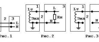
This option for obtaining three-phase voltage is based on the properties of inductance (the current lags behind the network voltage by a conventional 90-degree angle between the vectors) and capacitance (the voltage leads the current in the electrical circuit by a conventional 90-degree angle between the vectors). By combining inductive and capacitive elements with the load, with their specific combination, a phase shift of 120 degrees in voltage is obtained in the special circuit shown below. Each power value will require elements of corresponding size. They are shown in table No. 1.
Scheme
Table No. 1 for obtaining three-phase voltage on an active load
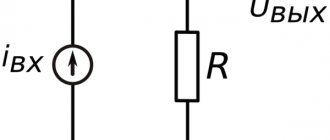
For an asynchronous engine, in which the equivalent of the stator windings are resistances and capacitances connected in parallel, the circuit and values of the elements will be different. They are given below in table No. 2 along with the diagram.
Table No. 2 for obtaining three-phase voltage on the windings of an asynchronous motor with a squirrel-cage rotor
The circuit requires metal-paper capacitors with a rated voltage of 250 V or more. For inductors, it is recommended to use a core from a 200 VA transformer. The number of turns is selected based on the measured current in an electrical circuit consisting of an inductor and a resistor with a known resistance connected in series. This circuit, together with a multimeter, is connected to a 100…300 Hz generator. Additionally, the inductance value is adjusted by the air gap in the core. Its presence is mandatory.
An increase in inductance will result in a decrease in current, and vice versa. The coincidence of the measured value with the calculated value indicates that the inductance of the required value has been obtained. This method is only suitable for a static load on the shaft of an asynchronous motor. If there are deviations, the phase characteristics of the voltage in the windings will change along with the torque. That is, the engine efficiency will deteriorate.
Installation of electrical wiring according to the diagram
Once the electrical wiring diagram in the garage is ready and everything you need has been purchased, you can begin installation. The entire operation can be divided into three stages: preparation, work in the external area and installation of electrical wiring indoors.
Preparation
Before starting work, it is traditional to prepare a set of electrician’s tools. It includes:
You will also need a pencil (painting pad, paint/brush) for marking surfaces, electrical tape and rubber gloves. The handles of all tools must be protected.
Preparatory work largely relates to the premises. This includes marking walls and/or ceilings, cutting channels, drilling holes for sockets, distribution panels. The nests are made with a hammer drill and a diamond bit. Grooves - with a hammer drill, grinder, or a simple "old-fashioned" set - a chisel and a hammer.
All these tools are far from the best choice: it is better to buy or find (rent) a “pro” - a wall chaser, which guarantees speed of work, evenness of the channels, and the absence of menacing clouds of dust in the garage. The depth and width of the grooves, as a rule, does not exceed 20 mm.
The electrical wiring diagram in the garage, when it comes to lighting, is implemented on the ceiling. When the floor is reinforced concrete slabs, the cable is simply laid between them and then covered with a sand-cement mixture or ready-made plaster. In the case of a monolith, the wiring is pulled into a corrugated sleeve. It is fixed with clamps “seated” on self-tapping screws.
Energy conversion methods
This section describes the main methods of converting 220 Volts into increased three-phase energy with a voltage of 380 V. There are many methods, but experienced specialists identify only five main ones:
- Using an electrical energy converter;
- Use of current transformers;
- Converting current from two-phase to three-phase;
- The use of a three-phase motor as a generator;
- Using a capacitor plan converter.
Voltage inverter
Energy converter
One of the simplest devices for instant energy conversion is an inverter, a device that increases the rated voltage in the network to the required values, the value of which depends on the technical characteristics of a particular device.
Household inverters generate stable voltage and do not require special skills to operate. Unfortunately, the power of such devices is low, but at the same time they are suitable for almost all three-phase household devices.
Star and delta connection
Inside, the device is equipped with a protection option against voltage surges and short circuits, which allows you to stabilize the frequency of current supply, eliminating sudden changes in amplitude in the electrical circuit, which often leads to breakdowns.
Attention! Constant energy with a minimum of voltage drops is obtained due to the operating principle of the converter. First of all, it ensures a reduction in the frequency of the alternating current, after which it generates a three-phase voltage with the required frequency
Three phase application method
With standard engineering equipment, three phases are connected in floor distribution boards, but only one of them is supplied to each separate residential premises.
Shields, as a rule, are installed in corridors or staircases, from where two additional phases can be brought into the room, but for this it is necessary to obtain written permission from the operating services.
A document for connecting two phases can be requested from the energy supply organization or agreed upon with the management company of the house. It is also necessary to install a three-phase device for commercial electricity metering.
Conversion circuit
The first method is electromechanical conversion
In order to get the result with your own hands and in the simplest way, you need to build an electromechanical voltage converter. This will require a minimum of effort, since you just need to find its ready-made components. To get maximum conversion efficiency, they are as follows:
- three-phase synchronous generator of suitable power;
- commutator electric motor, similar in power to a synchronous generator;
- powerful LATR.
The shafts of the engine and generator are rigidly connected. The engine is connected to the electrical network via LATR. Three phases are removed from the generator according to any diagram (star or triangle). The engine speed will decrease under load, so LATR will correct this. This adjustment is manual and inconvenient. Especially if the load changes quickly. But the only alternative to it can be one or another automation. The simplest solution is a centrifugal speed controller. Its contacts can be brought out to the body through rings and brushes.
And in order to reduce contact wear, the commutator motor must be connected to the network through a triac controlled by a centrifugal regulator. By setting it to a speed corresponding to the frequency of 50 Hz of the electric generator, you can work calmly without fear of changes in the load and mains voltage. For less powerful consumers of the order of 1...2 kW, excitation from a magnetic rotor is sufficient; for more powerful consumers, excitation from direct current is required. To control the excitation, it is advisable to use a dimmer with a rectifier.