Why do you need a frequency converter
A frequency converter is an indispensable equipment in any field where electric motors are used. It provides smooth starting, continuous automatic control of speed and torque during operation, as well as many other parameters of electric motor operation. In some applications, converters provide up to 50% reduction in energy consumption. Modern inverters with pulse-width modulation (PWM) are able to reduce inrush currents by an average of 4-5 times and withstand overloads of up to 200%.
Today on the Internet you can find a large number of recommendations and tips for selecting inverters, but in most cases they are general, non-specific and in no way applicable in practice. How to navigate the huge number of criteria and choose the right equipment? Recommendations are given by specialists from IEK GROUP, one of the leading Russian manufacturers and suppliers of electrical equipment: Artem Moshechkov (lead engineer) and Petr Ivlev (technical training specialist at the IEK GROUP Academy).
— Why install and use a frequency converter?
Artem Moshechkov: “This equipment solves several problems at once: it controls the rotation speed of the electric motor, protects it, and in certain modes provides energy saving. The inverter reduces excessive starting current and torque, eliminating shocks, jerks and increased mechanical loads on the drive. Also, the frequency converter allows you to protect the electric motor in case of a short circuit, insures against deviations from the rated network voltage, controls the temperature of the mechanism, and prevents overheating. Thus, the inverter ensures longer and more reliable operation of the drive, and minimizes maintenance and repair costs. In addition, in certain applications and operating modes, the frequency converter reduces energy consumption by 30-50%.”
— There is a task: to choose and buy a frequency converter. Where to begin?
Petr Ivlev: “The model and functional range of modern equipment offers many options for solving a wide range of problems. From the simplest to those providing control of the most complex automated electric drives. There are several main criteria based on which you should make a decision on choosing one or another frequency converter model.”
To choose the right inverter option, you must first decide: for what purpose the equipment is being selected, what specific tasks it should perform. Of course, it is necessary to know the operating conditions and the main characteristics of the electric motor, which requires an inverter to control.
Modern series of frequency converters include up to several dozen models. For example, the CONTROL-L620 IEK® line, launched by our company in 2017, includes equipment from 0.75 to 560 kilowatts. In the CONTROL-A310 IEK® family, the power range is up to 22 kilowatts, while already from 11 kilowatts it is possible to manufacture a converter with a built-in DC choke, which extends the service life of the converter. Rated voltages are 220 and 380 V.
A brand such as ONI® offers four brands of frequency converters: ONI-A400, ONI-M680, ONI-A650 and ONI-K800 - in the power range from 0.4 to 132 kW.
— Power, rated current, supply voltage: how to navigate these parameters?
Petr Ivlev: “The specified criteria are very important for optimal operation of the equipment.”
- The power of the inverter must be equal to or greater than the power of the motor. In cases of “heavy” applications, with high starting loads, it is allowed for the converter power to be higher by one, or less often by two stages. Modern frequency converters have a large power range. Let's look again at specific examples of equipment: the CONTROL-A310 series line includes models with power from 0.4 to 22 kW in HD mode and from 0.75 to 22 kW in ND mode. CONTROL-L620 frequency converters support power in HD mode from 0.75 to 500 kW, in ND mode - from 1.5 to 560 kW. There is also a narrower range: for example, inverters of the ONI-A400 line operate within a power range from 0.2 to 3.7 kW.
- The next criterion is the rated current. The electric drive does not operate in ideal mode - there is always a possibility of changes in dynamic loads on the shaft or exceeding the rated current values. Therefore, along with power, when choosing an inverter, attention is paid to the rated current of the electric motor and frequency converter. The operating value of this parameter for the inverter is taken either with a margin relative to the rated motor current, or the nominal value is equal to the nominal value. This is done in order to protect the electric drive from possible overloads.
- If we talk about the supply network voltage, the most common models that are used in production, in housing and communal services and other areas of the national economy are 220 and 380 V voltage converters. Let me remind you: the value of this parameter of the supply network and the electric motor must be the same.
— Which frequency converter is better - single-phase or three-phase?
Artem Moshechkov: “On the Internet you can read that a single-phase frequency converter has a less wide range of capabilities, but this is not so. He is able to solve all the tasks assigned.”
The input of the inverter of such an inverter is supplied with a single-phase voltage from the corresponding network, which at the output is formed into a three-phase voltage with a frequency from 0 to 400 Hz and above. Thus, using a single-phase inverter, you can connect a conventional three-phase asynchronous motor to a single-phase network. To do this, you need to connect the motor to the converter by correctly connecting the motor windings (for a voltage of 220 V). Such frequency converters are in the ONI family - this is the A400 series, which is designed to control asynchronous motors in systems of low power, but with high overloads.
Three-phase frequency converters are more common. They convert the voltage of a three-phase industrial network and regulate a large number of electric motor parameters.
Equipment examples:
- CONTROL-A310 IEK®,
- CONTROL-L620 IEK®,
- ONI-A400,
- ONI-M680,
- ONI-A650,
- ONI-K800.
INFLUENCE OF A FREQUENCY CONVERTER ON THE EFFICIENCY OF AN INDUCTION MOTOR
Published in 2022, Issue No. 8(62) August 2022, TECHNICAL SCIENCES | No comments yet
Fedyanin V. _ IN .
ORCID: 0000-0003-3126-9865, graduate student,
Omsk State Technical University
INFLUENCE OF A FREQUENCY CONVERTER ON THE EFFICIENCY OF AN INDUCTION MOTOR
annotation
This paper examines the issue of the influence of a frequency converter on the operating efficiency of an asynchronous motor. Full-scale experiments were carried out and a simulation model was developed in the MATLAB Simulink application, which allows one to estimate the consumed and useful power, cosφ, i.e., the energy efficiency of an asynchronous electric drive with sinusoidal voltage and voltage generated using pulse-width modulation. Based on the results of the study, it was found that the efficiency of an asynchronous motor connected to a frequency converter decreases by 3-7% in contrast to power supply with pure sinusoidal voltage.
Key words : variable frequency electric drive, frequency converter, asynchronous motor efficiency, chaotic pulse width modulation.
Fedyanin VV
ORCID: 0000-0003-3126-9865, Postgraduate Student,
Omsk State Technical University
IMPACT OF THE FREQUENCY CONVERTER ON THE EFFICIENCY FACTOR OF THE INDUCTION MOTOR
Abstract
In this paper, we consider the question of frequency converter impact on the efficiency of an induction motor. We conducted full-scale experiments in the MATLAB and Simulink. We developed a simulation model that allows estimating consumed and useful power, cosφ, ie, energy efficiency of an induction electric drive with sinusoidal voltage and voltage generated by pulse width modulation. According to the results of the study, it is established that the efficiency of an induction motor connected to the frequency converter is reduced by 3-7%, in contrast to the supply by pure sinusoidal voltage.
Keywords : frequency-controlled electric drive, frequency converter, induction motor efficiency, chaotic pulse width modulation.
Introduction
The asynchronous motor (IM) is widely used as electrical machines. About half of the electricity produced in a developed country ends up being consumed by electric motors, of which more than 90% are IM. For a relatively long period of time, IMs were mainly used for general purpose applications with constant rotor speed. However, the rapid development of high-power electronic devices and converter technologies over the past few decades has made it possible to achieve efficient speed control by varying frequency, leading to the advent of variable-frequency induction motors. The use of frequency converters (FCs) in combination with IM has advantages over other speed control solutions [1]. The main advantages of a variable frequency drive include:
– smooth regulation of the rotation speed of the electric motor rotor,
– smooth start of the electric motor,
– high rigidity of mechanical characteristics simultaneously with drive efficiency.
The inverter consists of a rectifier, a filter element, an inverter and a control system (CS). The rectifier circuit converts AC voltage into pulsating DC voltage using a diode bridge rectifier. The filter element smooths out the ripples of the rectified voltage. The inverter input from the output of the filter section receives a direct voltage, which the inverter converts into three-phase alternating voltage. Most often, the inverter power circuit is designed as a three-phase bridge circuit, which consists of six IGBT transistors with bi-directional conductivity. Regulation of the output frequency is carried out by the influence of control signals from the control system on the inverter. In the inverter control system, the master signal is converted into a series of pulses supplied to the IGBT transistors of the inverter, thereby providing the ability to adjust the amplitude of the output voltage and frequency. The output AC voltage is determined by the value of the rectifier voltage.
In most cases, static frequency converters using pulse width modulation (PWM) are used [2, 3]. The efficiency of modern inverters is about 95%. The use of PWM introduces additional harmonic components, the presence of which negatively affects the performance and efficiency of the electric motor. Thus, the inverter affects the characteristics of the IM and creates interference in the supply network. As a result, the efficiency factor (efficiency) of the blood pressure connected to the inverter decreases [4 – 6]. The presence of harmonics mainly increases the electrical losses in copper. An increase in losses will lead to an increase in engine temperature and, as a result, reduces its efficiency.
In connection with the above, studying the efficiency of an asynchronous motor connected to an inverter is an urgent task.
Theoretical part
A simulation model was developed in the Simulink program of the Matlab package to calculate the electrical parameters in Fig. 1. The model allows you to determine the root mean square value of the current IRMS, voltage URMS, input power Pin, output power Pout, reactive power Q, cosφ and efficiency of an asynchronous motor [7 – 10]. To ensure the operation of the simulation model, it is necessary to obtain phase voltage and current data, as well as load voltage, using an ADC and transfer them to the model in the form of numerical arrays. Next, the signals will be processed by amplitude.
Rice. 1 – Simulation model
In blocks 1, 2 of the presented model, the effective value of voltage and current is formed and scaled taking into account the transformation ratios of the sensors. RMS blocks calculate the true rms value of the input signal
, (1)
where is the signal arriving at the input of the block, T is the period, and is the fundamental frequency.
The true rms value of the input signal is calculated using a moving average algorithm, which is widely used in signal processing and statistics. Next, the Power block determines active, reactive power and cosφ. The measured power is distributed in all phases obviously evenly. The power consumed by the IM is determined as follows
(2)
In block 3, the useful power is calculated.
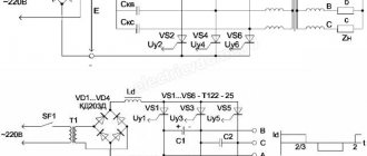
experimental part
In an experimental setup (Fig. 2), the efficiency of an asynchronous motor was determined in accordance with GOST 25941-83. The mutual loading method is used, in which two machines are mechanically connected to each other. Machine M1 operates in motor mode (AM) from a three-phase source, machine M2 operates in generator mode (direct current generator (DCG)) using a rheostat. The power on shaft M1 is determined by the expression
(3)
where is the power going to losses in the windings of the armature circuit of the loading machine ( = 9.8 Ohm); – mechanical losses of unit M1-M2; U, I – voltage and current at the load Rн. Since the rotor rotation speed is the same during the experiments, we neglect mechanical losses.
Rice. 2 – Scheme of the setup for the experiment
Measurements of phase currents and voltages were carried out using Hall effect sensors. The sensors provide galvanic isolation between the output and input circuits. The signals of three phases of instantaneous phase voltage values were taken from the output of sensors DN1-DN3, and instantaneous current values from the output of sensors DT1-DT3. The DN sensor removed the voltage at the load Rн.
To conduct the experiment, an induction motor with a 4AA50V4U3 squirrel-cage rotor was selected, the parameters of which are given in Table 1.
Table 1 – Technical data of the IM
| engine's type | power, kWt | At rated load | mp | mM | mk | ip | ||
| Slip, % | Efficiency, % | cosφ | ||||||
| 4AA50V4U3 | 0,09 | 8,6 | 55 | 0,60 | 2,0 | 1,7 | 2,2 | 2,5 |
In the first part of the experiment, the IM was connected to the inverter, tests were carried out with a fixed frequency of 50 Hz, the rms phase voltage was 191.2 V. In the second part of the experiment, the IM was connected to a three-phase adjustable source with an output sinusoidal voltage and a harmonic distortion coefficient of less than 5%. The RMS phase voltage was 189.5V with a frequency of 50Hz. (Fig. 3a, b) shows the rms values of phase currents and voltages.
Rice. 3 – RMS values of phase and voltages (a), RMS values of phase and currents (b),
In this case, the instantaneous values of voltage and current supplied to the input of the model are illustrated in (Fig. 4a, b).
Rice. 4 – Instantaneous values of phase current and voltage when connecting a three-phase sinusoidal voltage source (a), instantaneous values of phase current and voltage when connecting a frequency converter (b)
(Fig. 5a, b) shows the dependences of the input Pin and output Pout power for the case with an input sinusoidal voltage and with the voltage generated by the inverter.
Rice. 5 – Input power Pin (a), output power Pout (b)
From (Fig. 5a) it is clear that the input power when using an inverter is not constant, the maximum value is at the level. The power when supplied with sinusoidal voltage is constant and amounts to . In this case, the useful power is in both cases (Fig. 5b). (Fig. 6a, b) shows the dependences of the IM efficiency and cosφ. From the figure (Fig. 6a) it is clear that the minimum efficiency value when using an inverter is , while the efficiency of an IM operating from a sinusoidal voltage is .
Rice. 6 – Efficiency (a), cosφ (b)
Conclusion
Conclusions drawn based on the experimental results and the developed simulation model:
– IM connected to the inverter has an efficiency of 3-7% less than when powered by pure sinusoidal voltage. The increase in losses is associated with the appearance of higher harmonics;
– When operating the IM from the inverter, it is necessary to evaluate the efficiency of not only the system as a whole, but also the electric motor;
– To determine more accurately the power consumption values, it is necessary to use the true rms value determination.
List of literature / References
- Braslavsky I. Ya., Ishmatov Z. Sh., Polyakov V. N. Energy-saving asynchronous electric drive // M.: Academy. – 2004. – T. 256. – 202 p.
- Fedorov V.K., Fedyanin V.V. Algorithm for the formation of pulse-width modulation with a carrier frequency in the deterministic chaos mode // Omsk Scientific Bulletin. – 2022. – No. 2 (152). – pp. 45 – 49.
- Obukhov S.G., Chaplygin E.E., Kondratyev D.E. Pulse-width modulation in three-phase voltage inverters // Electricity. – 2008. – No. – pp. 23-31.
- Andrienko V. M. Determination of energy indicators of asynchronous motors when powered by static frequency converters // Electrical engineering and electromechanics. – 2010. – No. 3. – P. 5 – 7.
- Mikheev K. E., Thomasov V. S. Analysis of energy indicators of multi-level semiconductor converters of electric drive systems // Scientific and technical bulletin of information technologies, mechanics and optics. – 2012. – No. 1 (77). – pp. 46 – 52.
- Boyarskaya N.P., Dovgun V.P. Influence of the harmonic composition of currents and voltages on the efficiency of energy saving // Bulletin of the Krasnoyarsk State Agrarian University. – 2010. – No. – pp. 130 – 133.
- Kvashnin V. O., Tkachenko B. I. Methodology for indirect determination of the dynamic power factor of an asynchronous electric motor // Electrical engineering and electrical equipment. – 2006. – No. – pp. 230-231.
- Zakharenko V. S., Doroschenko I. V. Features of simulation modeling of an asynchronous motor for compiling a model taking into account switching and with asymmetric switching circuits // Bulletin of the Gomel State Technical University named after. Sukhoi software. – 2011. – No. 3 (46). – pp. 58 – 63.
- Kozlov D.V., Zmieva K.A., Shumikhina E.M. Experimental installation for studying engine characteristics at various loads and supply voltages EP-1 //Electrical complexes and control systems. – 2011. – No. – pp. 12-18.
- Petrenko A. N. Experimental study of heating of a frequency-controlled asynchronous motor with various power sources // Electrical engineering and electromechanics. – 2010. – No. – pp. 21 – 23.
List of literature in English / References in English
- Braslavskij I. Ja., Ishmatov Z. Sh., Poljakov VN Jenergosberegajushhij asinhronnyj jelektroprivod / I. Ja. Braslavskij, Z. Sh. Ishmatov, VN Poljakov // M.: Akademija. – 2004. – V. 256. – 202 p. [in English]
- Fedorov VK, Fedjanin VV Algoritm formirovanija shirotno-impul'snoj moduljacii s nesushhej chastotoj v rezhime determinirovannogo haosa / Fedorov VK, Fedjanin VV //Omskij nauchnyj vestnik [Omsk Scientific Bulletin]. – 2022. – No. 2 (152). – P. 45 – 49. [in Russian]
- Obuhov SG, Chaplygin EE, Kondrat'ev DE Shirotno-impul'snaja moduljacija v trehfaznyh invertorah naprjazhenija / Obuhov SG, Chaplygin EE, Kondrat'ev DE // Jelektrichestvo [Electricity]. – 2008. – No. 7. – P. 23-31. [in English]
- Andrienko VM Opredelenie jenergeticheskih pokazatelej asinhronnyh dvigatelej pri pitanii ot staticheskih preobrazovatelej chastity / VM Andrienko // Jelektrotehnika i jelektromehanika [Electrical engineering]. – 2010. – No. 3. – P. 5 – 7.
- Miheev KE, Tomasov VS Analiz jenergeticheskih pokazatelej mnogourovnevyh poluprovodnikovyh preobrazovatelej sistem jelektroprivoda / KE Miheev, VS Tomasov // Nauchno-tehnicheskij vestnik informacionnyh tehnologij, mehaniki i optiki. – 2012. – No. 1 (77). – P. 46 – 52.
- Bojarskaja NP, Dovgun VP Vlijanie garmonicheskogo sostava tokov i naprjazhenij na jeffektivnost' jenergosberezhenija / Bojarskaja NP, Dovgun VP // Vestnik Krasnojarskogo gosudarstvennogo agrarnogo universiteta . – 2010. – No. 4. – P. 130 – 133.
- Kvashnin VO, Tkachenko BI Metodika kosvennogo opredelenija dinamicheskogo kojeffectivea moshhnosti asinhronnogo jelektrodvigatelja / Kvashnin VO, Tkachenko BI //Jelektromashinostroenie i jelektrooborudovanie [Electrical machinery and electrical equipment]. – 2006. – No. 66. – P. 230-231.
- Zaharenko VS, Doroshhenko IV Special immitacionnogo modelirovanija asinhronnogo dvigatelja dlja sostavlenija modeli s uchetom kommutacii i pri nesimmetrichnyh shemah vkljuchenija / Zaharenko VS, Doroshhenko IV //Vestnik Gomel'skogo gosudarstvennogo tehnicheskogo universiteta im. P. O. Suhogo. – 2011. – No. 3 (46). – P. 58 – 63.
- Kozlov DV, Zmieva KA, Shumihina EM Jeksperimental'naja ustanovka dlja issledovanija harakteristik dvigatelja pri razlichnyh nagruzkah i pitajushhih naprjazhenijah JeP-1 / Kozlov DV, Zmieva KA, Shumihina EM // Jelektrotehnicheskie kompleksy i systemy upravleni ja. – 2011. – No. 1. – P. 12-18.
- Petrenko AN Jeksperimental'noe issledovanie nagreva chastotno-upravljaemogo asinhronnogo dvigatelja pri razlichnyh istochnikah pitanija / Petrenko AN // Jelektrotehnika i jelektromehanika. – 2010. – No. 5. – P. 21 – 23.
About control methods
There is a lot of theoretical information on the Internet about which option is better. In fact, you should base your choice not on assessments of the control method, but on the area of application of the frequency converter. In equipment that works with cranes, lifting mechanisms or broaching machines, the vector method is used. In pumps and fans, that is, in those mechanisms where the speed practically does not change, a scalar is usually used. Both of these methods solve the same problem: adjusting speed and changing torque.
— What is a PID controller, control inputs/outputs, and how important is it?
Petr Ivlev: “The proportional-integral-derivative controller (PID controller) controls external processes by analyzing feedback signals received by the frequency converter. This regulator is found in 95% of modern frequency converters.”
The simplest example of its use: it is required to maintain a constant pressure in the pipe of 5 Bar. The inverter reads signals from sensors, and the PID controller, using mathematical algorithms, ensures the required operating mode of the inverter.
We recommend reading: DIY DC voltage multiplier
The inverter reads signals from sensors, and the PID controller, using mathematical algorithms, ensures the required operating mode.
Application area
Manufacturers offer a wide range of drives used in areas where electric motors are used. Ideal solution for all types of loads, including pumps and fans. Mid-range systems are used in coal-fired power plants, mining, mills, utilities, etc. The rating range is as follows: 3 kV, 3.3 kV, 4.16 kV, 6 kV, 6.6 kV, 10 kV and 11 kV.
With the advent of an adjustable electric drive, controlling water pressure does not cause problems for the end user. The interface with a well-thought-out script structure is ideal for controlling pumping equipment. Thanks to its compact design, the drive can be installed in a variety of cabinet designs. New generation products have the properties of advanced technology:
- high speed and accuracy of control in vector mode;
- significant energy savings;
- fast dynamic characteristics;
- large low-frequency torque;
- double braking, etc.
Classification of frequency converters
According to the type of supply voltage, frequency converters are divided into types:
- single-phase;
- three-phase;
- high-voltage devices.
The main task of a frequency converter can be formulated as follows: transferring the working process to an economical mode by controlling the speed and torque of the motor, according to the specified technical parameters and the nature of the load.
In this case, the digital display of the device shows such system operating parameters as:
- the value of I and U of the engine;
- output values of frequency, speed, power and torque (f, v, P and M);
- displaying the status of discrete inputs for regulating the speed of rotation of the IM shaft and remote control of the system;
- duration of operation of the frequency converter itself.
According to the area of use, the types of inverters are:
- industrial use with power up to 315 kW;
- Inverter with vector control with power up to 500 kW;
- for controlling mechanisms with pump-fan type load (P 15 - 315 kW);
- frequencies for cranes and other lifting structures;
- for use in explosive environments;
- VFDs installed directly on the electric motor.
Safety precautions when connecting a frequency converter
There are several basic safety rules that need to be remembered when performing work on connecting frequency converters:
- It is strictly forbidden to touch live elements of the circuit with any part of the body. This can harm your health or even take your life. Before starting work, it is recommended to completely disconnect the equipment and use special electrical installation tools with protection against electric shock.
- It is worth remembering that even after the indicators on the device go out, voltage may remain in the circuit. To avoid electric shock when working with systems up to 7 kW, you must wait 5 minutes before starting work, with units over 7 kW - 15 minutes. This time should be enough for all capacitors in the circuit to discharge.
- Grounding is an integral part of any electrical circuit, including the frequency converter-motor circuit. It must be installed as a separate cable and under no circumstances can it be connected to the zero bus.
- It is worth remembering that turning off the frequency converter does not guarantee that there is no voltage left in other network nodes, so before repair or maintenance it is necessary to completely disconnect the circuit from the network.
Only qualified specialists with appropriate training and the necessary approvals can carry out work on connecting frequency converters.
How to connect and configure a frequency converter?
The general connection diagram for an asynchronous electric motor using a frequency converter is, in principle, not complicated, since all the main wiring is contained in the device housings. For a techie with practical knowledge, understanding it will not be difficult. In the circuit, a place is allocated for the converter immediately after the circuit breaker with a rated current equal to the rating of the electric motor. When installing the converter into a 3-phase network, it is necessary to use a three-pole circuit breaker that has a common lever. In case of overload, this will allow you to instantly disconnect all phases from the power supply network. The operating current must be equal to the current of one phase of the electric motor. For single-phase power supply, you should choose a circuit breaker with triple the current value of one phase.
In all cases, the inverter must be installed with circuit breakers connected to the neutral or ground wire.
In practice, setting up a frequency converter means connecting the cable cores to the visible contacts of the electric motor. The specific connection is determined by the nature of the voltage generated directly by the frequency converter. For 3-phase networks at industrial facilities, the electric motor is connected in a “star” - this circuit implies a parallel connection of the winding wires. For domestic use in single-phase networks, a “triangle” circuit is used (where U out does not exceed U nom by more than 50%).
The control panel must be located where it will be comfortable to use. The connection diagram for the remote control is usually shown in the user manual for the frequency converter. Before installation, before power is applied, the lever must be moved to the “off” position. After this, the corresponding indicator light should light up. By default, to start the device you need to press the “RUN” key. To smoothly increase the speed of the electric motor, you need to slowly turn the remote control handle. When rotating in reverse, you must reset the mode using the reverse button. Now you can move the handle to the working position and set the required rotation speed. It is worth noting that the control panels of individual inverters indicate not the mechanical speed, but the frequency of the supply voltage.
Why do you need to configure a frequency converter?
Once all electrical connections have been made, the frequency converter must be configured for commissioning. The process consists of four main points, these are:
- Setting the motor parameters is necessary to ensure that the inverter adapts to a specific motor.
- Entering parameters for starting and stopping the engine - the time to start and stop the engine, as well as the control mode, depend on these settings.
- Entering protective and limiting settings - at this stage, the limit values of various parameters are determined to protect the engine and the frequency generator itself from failure.
- Programming additional functions is the most extensive and variable item, since each specific task will use its own functions.
Correct execution of all stages of inverter programming will allow the electric motor to function in an optimal and safe mode and protect it from failure.
Stages of programming and setting up a frequency converter
Let us highlight the minimum set of actions for setting the parameters of the frequency converter:
- Entering passport data of the electric motor into the frequency converter;
- Entering the control principle:
- Constant frequency;
- Variable Frequency - If this option is selected, you must specify the source of the rotation speed reference.
- Set the control channel - that is, the source from which the start and stop command will come.
After completing these steps, the engine can be started, making sure that it rotates correctly. If the rotation is incorrect, this can be changed by switching phase wires or by adjusting the frequency converter.
We recommend reading: Simple diagrams for beginner radio amateurs
Direct starting, soft starters or frequency converters
Electromagnetic starter
There are several ways to start and control an electric motor. Basically, the engine is started by direct starting through an electromagnetic starter. With this approach, full voltage is applied to the motor and it reaches rated speed as quickly as possible.
The problem that operators face with direct-on-line starting is that the starting current pulse can be up to 7 times the motor's full load current. For a very short period of time, a very strong pulse of current is applied to the motor and its components. If a powerful engine starts and stops frequently, it will wear out faster and fail, and can also damage the actuator that operates from it.
Soft starter
On the contrary, a soft starter reduces starting currents by up to 2-4 times, reducing the load and torque applied to the motor. This approach allows the motor to accelerate at a speed that is determined by the settings of the soft starter itself. The operator can set a specific acceleration time, and the engine will accelerate smoothly from start to the designated time. This approach allows you to reduce the starting current, reduce the risk of premature equipment failure and save some energy. Soft starters are ideal in applications where speed ramping and torque control are critical components, and in piping systems to avoid water hammer when starting and stopping pumps.
A frequency converter
A VFD takes this concept one step further by allowing the operator to always control the starting current and motor speed. The VFD can control the motor both during the start/stop cycle and while it is running. A VFD is needed where full speed control is required and where high energy consumption is a major concern.
In terms of initial investment, a soft starter is a less expensive option, but the economic effect of introducing a frequency converter can pay for its cost many times over.
Operating principle of the frequency converter
The fundamental drive is determined by a double conversion inverter. The principle of operation is to:
- input variable toxinusoidal type 380 or 220V is rectified by a block of diodes;
- then filtered by capacitors to minimize voltage ripple;
- then the voltage is supplied to microcircuits and transistor bridges, which create a 3-phase wave from it with set parameters;
- At the output, rectangular pulses are converted into sinusoidal voltage.
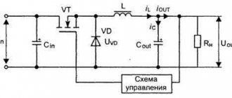
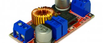
Frequency converter circuit
Below is a typical diagram of a frequency converter. The input mains voltage, three-phase or single-phase, is supplied through an optional input filter to the diode bridge terminals. An uncontrolled diode (or controlled thyristor) bridge converts the alternating mains voltage into a constant pulsating voltage. To filter ripples, a DC link consisting of one or more capacitors C is used.
Frequency converter circuit
The voltage in the DC link after rectifying the three-phase voltage will be equal according to the formula: 380 * 1.35 = 513 V.
The DCL choke in the DC link allows you to further smooth out voltage ripple after the diode bridge and performs the function of reducing rectifier harmonics injected into the supply network.
Transistors T1-T6 of the inverter, using a special algorithm of the control system, generate 3 packets of pulses at the motor terminals, spaced across three phases by 120 degrees in time. The figure below shows only one phase: a packet of output pulses of pulse width modulation (PWM), passing through the motor winding, is smoothed to a shape resembling a sine wave. The PWM pulse frequency (reference frequency) in industrial converters is usually 3-4 kHz, but for low power inverters it can go up to 16 kHz. The higher the PWM frequencies, the less harmonic distortion of the “sine wave” will be at the inverter output. But at the same time, heat losses on power transistors increase, which reduces efficiency. In Toshiba inverters, the frequency can be changed, thus regulating heat losses.
PWM inverter
The output voltage of the frequency converter will always be lower than the input mains voltage. This is due to losses in the power module and the algorithm for obtaining PWM pulses.
An additional filter can be installed between the frequency converter and the electric motor, which can significantly improve the shape of the output voltage after the frequency converter. This is necessary to ensure that the PWM pulses do not destroy the insulation of the motor windings and do not cause overvoltage at the end of a long cable. Learn more about output filters.
Features of the use of inverter for various equipment
— Frequency converter for pumping equipment: what does it give?
Artem Moshechkov: “In the case of pumping equipment, it is most often necessary to protect the pipeline from water hammer during pump startup, and the electric drive itself from premature failure and operation in emergency mode. Of no small importance is optimizing energy consumption and maintaining constant pressure in the water supply system.”
To solve these problems, it is necessary to ensure a smooth start of the pumps and a smooth change in the rotation speed of the electric motor. Moreover, the range of values should be quite wide: during peak load, the electric drive operates at rated speed, providing the required water flow. With little disassembly, it is maintained in working condition, consuming the minimum amount of electricity that is needed at the moment. Also in the housing and communal services sector, with the help of inverters, it is possible to create an automated cascade pump system, when, depending on the water supply in residential buildings, one pump or, for example, three operates. Using special functions, the frequency converter allows you to save energy - this occurs by automatically stopping a running pump when there is no water flow in the system.
The following series of inverters can handle this task: CONTROL-A310 IEK®, CONTROL-L620 IEK®, ONI-A400, ONI-M680. However, the best choice would be the ONI-A650 frequency converter, designed specifically for use in ventilation systems and pumping units. Already in the basic configuration it contains a special cascade pump control board, which allows you to combine up to 5 pumps into a single cascade.
Opinion: The ONI-K800 frequency converter was used in the drive of a water supply system pump and in the drive of a conveyor. Has proven itself on the positive side. During setup and during operation, power and control cables were easily installed, the converter was simply configured from the front panel. It has great protection functionality and a large number of inputs and outputs. Head of the EMP Department of Uralgipromez JSC D.N. Tomashevsky.
— What frequency converters are suitable for lifting mechanisms (crane equipment, winches)?
Petr Ivlev: “A modern crane mechanism is a very complex system. Therefore, a frequency converter for an electric drive of such a mechanism must meet high requirements: have a high overload capacity (up to 200%), be able to control the mechanical brake of the electric motor, be able to connect a braking resistor (built-in braking module) and organize feedback to regulate the rotation speed of the electric motor. The latter is necessary to ensure rapid exchange of information between parts of the system, continuous monitoring of all processes and precise control of parameters during operation of the most complex crane mechanism.”
Frequency converters for electric motors of lifting mechanisms make it possible to organize reliable control of the electric drive when lifting and lowering a load, turning the arrow, providing vertical and horizontal movement without swinging, at different speeds, thus guaranteeing maximum productivity.
Depending on the crane model, these can be the following types of frequency converters:
- to ensure smooth movement of the crane, we can recommend the CONTROL-L620 IEK®, ONI-M680 and ONI-K800 series;
- For reliable operation of the lifting winch, depending on the task, M680 and K800 are suitable.
— How does a frequency converter work in the case of conveyor and conveyor equipment?
Artem Moshechkov: “When such mechanisms are started, a starting current occurs that exceeds the rated current by 6-7 times, as well as a large load on the mechanism parts and, as a result, increased wear of components or overheating of the electric motor. This is the most common cause of failure of such equipment. Further, during operation, the drive usually rotates at the same speed. Therefore, for continuous transport mechanisms, smooth acceleration and braking without jerking, slipping, stopping, as well as a constant set speed are very important. Consequently, a frequency converter for such equipment solves the problem of ensuring a constant speed of a conveyor or conveyor, increasing the level of reliability (as it significantly reduces the number of failures of both mechanical and electrical origin), and eliminating overloads during startup.”
The use of frequency converters with electric motors of conveyors and conveyors allows not only to automate the start, speed control and stopping of the belt, but also to create more complex algorithms for equipment operation (depending on the selected inverter model and connected sensors).
We recommend reading: Types of batteries: detailed classification of batteries by size, composition and other parameters
Opinion: A CONTROL-L620 IEK® frequency converter with a rated power of 5.5 was installed on the infeed conveyor in plant No. 2 for drying grass meal. The operating mode of the converter is round-the-clock “start-stop”. The equipment has proven itself on the positive side. During testing, all functions worked in the stated normal mode; no comments were identified during operation. Deputy General Director for IT PJSC Borovskaya Poultry Farm S.M. Solkin.
— Does it make sense to use frequency converters for fan equipment?
Petr Ivlev: “Yes. The inverter for fan equipment regulates the rotation speed of the electric drive shaft, allowing you to save on electricity. If an additional sensor is installed, which transmits operational data about the current air demand to the converter, the latter changes the rotation speed of the electric motor. This allows you to save energy by 20-40%. In addition, the inverter reliably protects the fan electric drive from current surges and overloads due to the smooth start and the same smooth stop of the shaft.”
We recommend frequency converters of the following series for installation on fan equipment: ONI-A650, CONTROL-A310 IEK®, CONTROL-L620 IEK®, ONI-A400.
— “Heavy” or “normal” operating mode of the frequency converter - which one to choose?
Artem Moshechkov: “Modern inverters ensure the start and operation of engines in normal or heavy duty. The abbreviations ND (normal) and HD (severe) are used to designate them.”
In ND mode, the torque value is constant, regardless of the engine speed. In particular, pumps work this way.
Heavy Duty (HD) is characterized by variable torque loads - as is the case with extruders, conveyors or compressors. At the same time, there are frequency converters that support two of these modes at once, which allows you to save budget when designing various systems. For example, IEK® frequency converters of the CONTROL-A310 and L-620 series can operate in both ND mode and HD mode. Also, both modes support the ONI-M680 inverter.
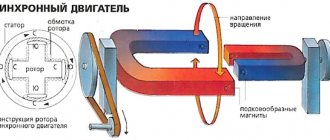
What is Variable Frequency Drive?
Variable frequency drive (variable requency drive, VFD) is a system for controlling the rotor speed of an asynchronous (synchronous) electric motor. It consists of the electric motor itself and a frequency converter.
A frequency converter (frequency converter) is a device consisting of a rectifier (DC bridge) that converts alternating current of industrial frequency into direct current and an inverter (converter) (sometimes with PWM) that converts direct current into alternating current of the required frequency and amplitude. Output thyristors (GTOs) or IGBTs provide the necessary current to power the motor. To avoid overloading the converter when the feeder is long, chokes are installed between the converter and the feeder, and to reduce electromagnetic interference, an EMC filter is installed. With scalar control, harmonic currents of the motor phases are formed. Vector control is a method of controlling synchronous and asynchronous motors, which not only generates harmonic currents (voltages) of the phases, but also provides control of the rotor magnetic flux (torque on the motor shaft).
Application of frequency drive
Frequency converters are used in:
- high power marine electric drive
- rolling mills (synchronous operation of stands)
- high-speed drive of vacuum turbomolecular pumps (up to 100,000 rpm)
- conveyor systems
- cutting machines
- CNC machines - synchronization of the movement of several axes at once (up to 32 - for example in printing or packaging equipment) (servo drives)
- automatically opening doors
- mixers, pumps, fans, compressors
- household air conditioners
- washing machines
- urban electric transport, especially trolleybuses.
The greatest economic effect comes from the use of VFDs in ventilation, air conditioning and water supply systems, where the use of VFDs has become virtually a standard.
Advantages of using VFD
- High control accuracy
- Energy savings in case of variable load (that is, operation of the electric motor at partial load).
- Equal to the maximum starting torque.
- Possibility of remote diagnostics of the drive via an industrial network
- phase failure detection for input and output circuits
- engine hour recording
- aging of main circuit capacitors
- fan malfunction
- Increased equipment life
- Reduced hydraulic resistance of the pipeline due to the absence of a control valve
- Smooth engine start, which significantly reduces engine wear
- A VFD usually contains a PID controller and can be connected directly to a sensor of the controlled variable (for example, pressure).
- Controlled braking and automatic restart in the event of a power failure
- Picking up a rotating electric motor
- Rotation speed stabilization when load changes
- Significant reduction in acoustic noise of the electric motor (using the Soft PWM function)
- Additional energy savings from optimization of electrical excitation. engine
- Allows you to replace a circuit breaker
Disadvantages of using a frequency drive
- Most VFD models are a source of noise (requires installation of High Frequency Interference Filters)
- Relatively high cost for high-power VFDs (payback minimum 1-2 years)
Application of frequency converters at pumping stations
The classic method of controlling the supply of pumping units involves throttling the pressure lines and regulating the number of operating units according to some technical parameter (for example, pressure in the pipeline). In this case, pumping units are selected based on certain design characteristics (usually with a performance reserve) and constantly operate at a constant speed, without taking into account changing costs caused by variable water consumption. At minimum flow, the pumps continue to operate at a constant speed, creating excess pressure in the network (the cause of accidents), while a significant amount of electricity is wasted. This, for example, happens at night, when water consumption drops sharply. The main effect is achieved not by saving energy, but by significantly reducing the cost of repairing water supply networks.
The advent of an adjustable electric drive made it possible to maintain constant pressure directly at the consumer. Variable-frequency electric drives with asynchronous electric motors for general industrial use are widely used in world practice. As a result of adaptation of general industrial asynchronous motors to their operating conditions in controlled electric drives, special adjustable asynchronous motors are created with higher energy and weight-size-cost indicators compared to non-adapted ones. Frequency control of the shaft rotation speed of an asynchronous motor is carried out using an electronic device, which is commonly called a frequency converter. The above effect is achieved by changing the frequency and amplitude of the three-phase voltage supplied to the electric motor. Thus, by changing the parameters of the supply voltage (frequency control), you can make the motor rotation speed both lower and higher than the nominal one. In the second zone (frequency above the nominal), the maximum torque on the shaft is inversely proportional to the rotation speed.
The frequency conversion method is based on the following principle. Typically, the industrial network frequency is 50 Hz. For example, let's take a pump with a two-pole electric motor. Taking into account sliding, the engine rotation speed is about 2800 (depending on power) revolutions per minute and gives the output of the pumping unit the nominal pressure and performance (since these are its nominal parameters, according to the passport). If you use a frequency converter to reduce the frequency and amplitude of the alternating voltage supplied to it, the engine rotation speed will correspondingly decrease and, consequently, the performance of the pumping unit will change. Information about the pressure in the network enters the frequency converter unit from a special pressure sensor installed at the consumer; based on this data, the converter accordingly changes the frequency supplied to the engine.
The modern frequency converter has a compact design, a dust- and moisture-proof housing, and a user-friendly interface, which allows it to be used in the most difficult conditions and problematic environments. The power range is very wide and ranges from 0.18 to 630 kW or more with a standard power supply of 220/380 V and 50-60 Hz. Practice shows that the use of frequency converters at pumping stations allows:
- save energy (with significant changes in consumption) by adjusting the power of the electric drive depending on the actual water consumption (saving effect of 20-50%);
- reduce water consumption by reducing leaks when the pressure in the main line is exceeded, when water consumption is actually small (by an average of 5%);
- reduce costs (the main economic effect) for emergency repairs of equipment (the entire water supply infrastructure due to a sharp reduction in the number of emergency situations caused, in particular, by water hammer, which often happens when an unregulated electric drive is used (it has been proven that the service life of the equipment increases by at least 1. 5 times);
- achieve certain heat savings in hot water supply systems by reducing losses of heat-carrying water;
- increase the pressure above normal if necessary;
- comprehensively automate the water supply system, thereby reducing the wages of service and duty personnel, and eliminate the influence of the “human factor” on the operation of the system, which is also important.
According to available data, the payback period for a project to introduce frequency converters ranges from 3 months to 2 years.
Power loss when braking an electric motor
In many installations, an adjustable electric drive is tasked not only with smoothly regulating the torque and speed of rotation of the electric motor, but also with the task of slowing down and braking the elements of the installation. The classic solution to this problem is a drive system with an asynchronous motor with a frequency converter equipped with a brake switch with a braking resistor.
At the same time, in the deceleration/braking mode, the electric motor operates as a generator, converting mechanical energy into electrical energy, which is ultimately dissipated by the braking resistor. Typical installations in which acceleration cycles alternate with deceleration cycles are the traction drive of electric vehicles, hoists, elevators, centrifuges, winding machines, etc. The electric braking function first appeared on a DC drive (for example, a trolleybus). At the end of the twentieth century, frequency converters with a built-in recuperator appeared, which allow the energy received from the engine operating in braking mode to be returned back to the network. In this case, the installation begins to “make money” almost immediately after commissioning.
Operating principle of frequency converter
Frequency converters
Still have questions? ENERGOPUSK specialists will answer your questions: 8-800-700-11-54
(8-18, Mon-Tue)
Management methods
The microcontroller of the frequency converter runs software that controls the main parameters of the electric motor (speed and torque). The main control methods for brushless motors used in frequency converters are presented in the table below.
| 1:101 | 5-10 | Not available | Short | Very low | Low-efficiency: pumps, fans, compressors, HVAC (heating, ventilation and air conditioning) |
| >1:2002 | <1-2 | High | High | High-performance: cranes, elevators, transport, etc. | |
| >1:2002 | <1-2 | High | High | ||
| >1:2002 | <1 | High | High | ||
| >1:2002 | <1-2 | High | High | High performance: electric traction, fast field weakening |
Control using remote control
Unlike the control panel, the console can have a cable up to 500 m long, through which serial interface signals are transmitted.
The control panel has keys RUN (Start), STOP/RESET (Stop/Reset), JOG (operation in pulse or jog mode). You can also reset errors, change the frequency and direction of rotation of the engine, and change other parameters.
Control via analog input
The PR6000 frequency converter has two analogue inputs – AI1 and AI2. This sets it apart from other models with one analog input.
Input AI1 can be used for voltage control with an input impedance of 47 kOhm. Input AI2 has a choice, which is made by a switch: current input with an input resistance of 500 Ohms, or voltage input.
Control via digital inputs
The PR6000 converter has 8 discrete (digital) inputs: FWD (forward/stop), REW (reverse/stop) and 6 inputs DI1…DI6.
The FWD and REW inputs can operate in two- and three-wire mode, with the third wire being programmed on one of the inputs DI1…DI6. The speed control mode selection is set in parameter P077.
Digital inputs DI1...DI6 are multifunctional; they are programmed for different functions, which are launched when the corresponding input is activated.
Possible functions: multi-speed selection, acceleration/deceleration selection, forward/reverse JOG operation, stop control, frequency increase/decrease, fault alarm input, start pause, three-wire start/stop control, DC braking , error/message reset, sweep frequency operation, counter enable/reset/input. In total, you can select up to 20 different parameters, which are set in parameters P071...P076 for each input. Activation of discrete inputs occurs by short-circuiting the desired input to the COM terminal. Moreover, this can be done in different ways - via the controller output, relay contacts, sensor or manual button. The digital and analog inputs are shown below.
Serial control
When operating via the RS-485 interface, the frequency converter is controlled by a controller or a personal computer through a special RS-485/RS-232 converter adapter.
Through this interface, the converter can not only receive commands to change parameters and state, but also provide information about its current state to other devices. Also, communication with other converters can be supported via the RS-485 interface.
Next, we’ll talk about methods for operational control of inverter modes.
Technical features of using a frequency drive
- To ensure high performance, you can freely switch to any mode in the settings.
- Almost all devices have diagnostic functions, which allows you to quickly resolve the problem. However, it is recommended to first check the settings to eliminate the possibility of involuntary actions by employees.
- An adjustable drive can synchronize conveyor processes, or set a certain ratio of interdependent quantities. Reducing equipment leads to optimization of technology.
- In the auto-tuning state, the motor parameters are automatically stored in the memory of the frequency converter. This increases the accuracy of torque calculations and improves slip compensation.