The principle of operation of the protection
The structure of the differential protection is busbars, generators, power transformer stations, overhead or cable lines. It has high sensitivity, which ensures its speed.
For your information! The operating principle of transformer differential protection is to control the currents at the beginning and end of an electrical circuit. For this purpose, transformer stations are used, which are connected to the device using cables when they are located within the coverage area of one distribution line.
If the protected area is large and its boundaries are located far from each other, then it is recommended to use two half-sets of protection, to connect which an auxiliary cable line is used. This is typical when installing overhead and cable lines.
Balanced voltage circuit
If the currents at the beginning and end of the protection section are the same, the protection does not operate. This occurs if rated currents flow during a short circuit outside the protected area. When a short circuit occurs, power from the electrical network flows to the short circuit point. If the power supply is one-way, for example, as with generators and transformers, then a large current flows from the source to the protected side, as a result of which it is given to the consumer.
Cable and overhead lines have two-way currents, so the point of damage is marked at both ends. In this case, protection is triggered, which forces the mechanism to turn off the object on both sides. To realize this, differential pressure switches are used, which are selected depending on the characteristics of the object.
Transformer station protection
Features of differential protection of three-winding transformers and autotransformers
For three-winding transformers with a power of 63 MVA or more and autotransformers, it is necessary to ensure the reduced maximum multiplicity of current transformers is more than 25 (9-6), under this condition the following can be accepted: kper = 2.5, kin.brake = 1.0, v = 1.25 . The setting “g” can be taken g = 0.3.
The remaining settings are selected in the same way for all groups.
The operating current of the differential current cut-off is selected according to the greater of two conditions: detuning from the magnetizing inrush current and detuning from the maximum external short circuit current.
According to the condition of detuning from the maximum current mode of the external short circuit according to the following expression:
| (9 – 7) |
where koffset is the detuning coefficient, koffset can be taken = 1.1; knb = 0.7, if current transformers with a secondary rated current of 5 A are used for the protected transformer on all sides; knb = 1.0 if current transformers with a secondary rated current of 1 A are used on either side. The “g-High” setting can be used if a voltage increase of more than 15% of the rated branch voltage is possible. The “Jnrush Ratio” setting can be taken equal to 12%. The “Jnrush Time” setting can be set to 5 s if there is no sufficiently accurate data on the decay time of the magnetizing inrush current. To explain the choice of secondary current equalization coefficients, consider a three-winding transformer with different rated powers of the sides, so that, in addition to amplitude equalization, we can use the possibility of changing the reference value of the AC channel. Transformer parameters: S110 = 25 MV•A; U = 110/35/6.3 kV; S35 = 20 MV•A; S6 = 5 MV•A; I110 = 131 A; I35 = 330 A; I6 = 458 A. The same for a total power of 25 MVA: I110 = 131 A; I35 = 412 A; I6 = 2294 A; current transformers on the 110 kV side: nTT = 300/5; on the 35 kV side: nCT = 600/5, on the 6.3 kV side nCT = 600/5. We determine the coefficients of change in the reference values of the AC channel on the 110 kV, 35 kV and 6.3 kV side:
After changing the reference values of the channels, the reference currents on the 110, 35 and 6 kV sides will be, respectively: 131 A, 330 A and 458 A.
The selection of the necessary vector groups to compensate for angular shift is described in detail above. This concludes the calculation of the differential protection response settings for the RET316 type transformer.
Types of differential protection
The differential protection can be longitudinal or transverse. The devices keep short circuits under control.
Transverse
Used to simultaneously protect several power lines. The principle of operation is to compare the load values of transformer stations. Transverse allows the installation of CTs on different power lines that depart from the same electrical power source.
You may be interested in this All about uninterruptible power supply
Current circuits are connected to different values of power lines. If there is a short circuit on one of the lines, the load increases on the second. The reaction of the pressure switch occurs at different values of the current load on the lines.
Note! When the transverse differential protection is triggered, maintenance personnel can independently determine the damaged area.
Engine differential protection
Longitudinal
This type ensures full operation of transformer motors. It is characterized by absolute selectivity and reliability for power lines that are short in length. It is possible to use longitudinal protection with other types.
Differential protection compares the values of current loads that flow in sections of the line through the device. To measure current strength, transformer stations are used. On two CTs, circuits are connected by points to a pressure switch in such a way that it is affected by the difference in current values.
Longitudinal view of the device
An unbalance current may occur in these circuits:
- if magnetizing currents appear in the windings of the transformer station. This happens if you switch the xx mode to full load, which leads to an increase in the nominal value;
- a transformer station does not always have the same technical characteristics as the CT with which it works in tandem. To avoid negative consequences, after the release of the transformer, tests are carried out to determine the most suitable transformer stations for operation in pairs;
- When the windings are connected differently, unbalance currents appear. It is impossible to equalize the value of electric currents if you select the turns of current transformer stations.
For your information! The unbalance current compensation device is installed in a modern microprocessor-based longitudinal differential protection.
Triggered shutdown
Basic transformer protection
Any relay protection of a transformer is aimed at triggering in the event of damage or abnormal operation of this device.
It should be noted that some of them are aimed at instantaneous shutdown in the event of an accident, while others only provide a warning signal to personnel. In turn, the staff already acts according to instructions that are developed directly and individually for each supply circuit and distribution substation. In order to see what type of accident occurred, signal relays (blinker) are used in parallel, which must be signed in accordance with the rules. To protect the transformer, a whole range of measures and electromechanical circuits are used, here are the main ones:
- Differential protection. It protects against damage and short circuits both in the windings and on the external terminals. Only affects shutdown;
- Gas protection. Protects against excess pressure inside the expansion tank due to the release of gases or the release of oil, as well as from reducing its level below a certain critical reading;
- Thermal protection. It is organized mainly on thermal alarms (TS), which send a signal to the personnel console or to turn on the cooling fans. This type of additional protection serves as a warning during the initial stages of emergency situations. In this case, the choice of the vehicle itself is not important, the main thing is to set the correct range at which the signal should be given. The maximum permissible oil temperature is 95 degrees;
- Minimum voltage protection. Provides shutdown when the input voltage level drops below the permissible level. Often has a time delay, which will make it possible not to react to small drawdowns;
- From short circuit to ground. This is done by installing current transformers in the connection between the housing and the ground loop;
- Maximum current (MTZ) acts as a protective mechanism both during short circuits in the secondary current circuit and during large overloads.
Transformer differential protection
This is one of the fastest and most important protections, which is necessary for reliable operation of the following transformers:
- On step-down single-operating transformers whose power is higher than 6300 kVA;
- When these devices operate in parallel with a power of 4000 kVA and above. With such a connection, this protection guarantees not only speed, but also selective shutdown of only the device that is damaged, and not a complete blackout of the powered electrical equipment, which entails losses in production or the appearance of defective products;
- If the MTZ of the transformer does not provide the necessary sensitivity and shutdown speed, and can operate with a time delay of more than one second;
- If the transformers are of lower power, then a conventional current cut-off connected to a current relay is used.
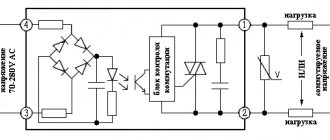
The operating principle of differential protection is based on comparing the current, or more precisely, its magnitude. The comparison occurs at the end and at the beginning of the protected section. The section in this case is one of the step-down windings. That is, one current transformer is installed on the high side and the other on the low side.
The diagram shows the connection of transformers TT1 and TT2 connected in series. T is a current relay that remains inactive during normal operation, when the currents are the same, that is, their difference will be equal to zero. When a short circuit occurs, a current difference will appear in the protected section of the circuit and the relay will close, thereby disconnecting the transformer from the network. This type of protection will operate both during interturn and phase-to-phase faults. The instantaneous operation of such protective equipment does not require a time delay, since its rapid operation is its main positive factor. The selection of the T relay actuation insert must be made by electrical laboratories or by the designers of this equipment. For each specific case, the relay pull-in current level can be changed to avoid false alarms.
Operating principle of gas protection of transformers
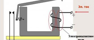
Gas protection of power transformers is based on the operation of a gas relay, which is shown in the figure.
In a special window, bubbles can be seen when gases are released.
The relay is a metal vessel in which two special floats are located. They are embedded in an inclined pipeline. In turn, this pipeline is the connecting link between the cooling housing with a radiator and the expansion tank.
If the transformer is in working order, the gas relay is filled with transformer oil, and the relay floats are in a certain inoperative state, since there is oil inside them. The floats are directly connected to a contact group, which has an emergency and warning signal. In normal condition, the contacts are in the open position. When the oil is heated, in the event of an abnormal process in operation, gas is released from it, which, according to the law of physics, naturally rises upward. In the path of the gases there is a gas relay and its floats, which, when a certain amount of gas that raises it accumulates, begins to move, which opens the first stage. With a more rapid development of events, the second float is set in motion and closes the second stage, which leads to shutdown. Taking an oil sample and testing it, as well as chemical analysis, allows us to determine the nature of the damage.
From practice, not every operation of the gas relay leads to sampling and analysis of the oil; sometimes, when filling, air can enter the system, which will rise during operation and can cause this protection to operate. To do this, you just need to open the special tap (valve) located on the relay body and release the air. This procedure is performed the first time the warning float is activated.
The choice of the relay itself is based on the design of the transformer and its dimensions. Very often, several types of this device are used: RGChZ-66, PG-22, BF-50, BF-80, RZT-50, RZT-80. All of them have a viewing window and a sealed housing.
What does it protect against?
Differential protection eliminates the impact of currents on the motors of electrical objects as a result of accidents that may occur in the controlled area. The protective device is mounted on the pressure switch of the electric motor. To ensure proper operation of the measuring circuit, it is recommended to ensure that the incoming and outgoing currents are in phase.
Transverse protection is installed on lines with voltages from 35 to 220 kV. It is used on parallel power lines that have two voltage sources. If the power supply is two-way, then transformer stations must be installed at both ends of the line.
Longitudinal differential protection is used in transformer and autotransformer stations. It is used to protect a single transformer station at a substation. The differential protection is used at autotransformer stations with a power of up to 6300 kV. A longitudinal view is necessary for transformer stations that operate in parallel and have a power of more than 100 kV, provided that the current cutoff is performed correctly.
You might be interested in How to make diagrams
Types of protection
All equipment used in power distribution installations is protected from short-term overloads and disconnections from the network. Transformer surge protection is needed to ensure that the device can withstand voltages much higher than the rated voltage.
To protect against overvoltage, fuses are selected. In the event of an emergency shutdown of one of the transformers, several of the same devices put into operation will compensate for the rated voltage in the network, thereby avoiding an emergency situation.
Basic and backup types of protection for power transformers:
- Fuses and three-phase switches;
- Transformer differential protection;
- Gas protection of transformer;
- Transformer differential protection;
- Fire protection;
- Alarm insurance using special computer programs.
Video: checking transformer protection
Some phenomena can cause significant differential current when there is no fault, and these differential currents are usually sufficient to cause the intermediate differential relay to trip. However, in these situations the differential protection should not trip the system as it is not an internal fault of the transformer.
3 Main causes of false differential current in a transformer
Differential power transformer protection circuit
Such phenomena may be associated with nonlinearities in the transformer core. Some of these situations are discussed below //
- Starting currents
- Conditions of overexcitation
- Transformer voltage
Starting currents
Magnetizing inrush current in transformers results from any sudden change in magnetizing voltage. Although usually considered as a result of transformer excitation, magnetizing inrush can also be caused by //
- External fault occurs
- Voltage restoration after eliminating an external fault
- Changing the nature of the fault (for example, when a trip from an earth fault changes to a phase from an earth fault)
- Analogue synchronization of the connected generator
Example of inrush current after a reclosing operation measured at a distribution substation circuit breaker.
Figure 3 - Example of starting current measured at a substation (many distribution transformers together)
Because the magnetizing branch representing the core appears as a shunt element in the equivalent circuit of the transformer, the magnetizing current upsets the balance between the currents at the transformer terminals and therefore experiences the differential relay as a "false" differential current .
However, the relay must remain stable during surges. Moreover, from the point of view of transformer life, tripping during surges is a very undesirable situation ! Current interruption of pure inductive nature creates high overvoltage which can compromise the insulation of the transformer and be an indirect cause of internal fault).
The main characteristics of starting currents are summarized below //
- Typically contain DC offset, odd harmonics and even harmonics.
- Typically consists of unipolar or bipolar pulses separated by intervals of very low current values.
- Peak values of unipolar inrush current pulses decrease very slowly.
- The time constant is usually much larger than the time constant of exponentially decaying DC offset fault currents.
- The second harmonic content starts at a low value and increases as the inrush current decreases.
Read more about practical considerations of transformer inrush current //
Return to Situations ↑
Conditions of overexcitation
Overloading a transformer can result in unnecessary operation of the transformer differential relays . This situation can occur in generator sets when a single generator is split during VAR export. The resulting sudden voltage rise expressed across the windings of the transformer block from VAR load loss can lead to exceeding rated hertz voltages and hence an overexcitation event .
This may also occur in transmission systems where a large reactive load is disconnected from the transformer while the primary winding remains on .
When the primary winding of a transformer is inverted and saturated, there is more power going into the primary transformer than leaving the secondary winding. A differential relay with its inputs supplied by properly selected current transformers to match the ratio and phase shift will perceive this as the difference in current between the primary and secondary windings and will therefore operate.
This would be an undesirable operation since there would be no internal fault since the current imbalance is created from the overexcitation condition.
Since overexcitation manifests itself in the production of odd harmonics, and since the third harmonic (and other triplets) can be effectively canceled in the Δ transformer windings, the fifth harmonic can be used as a limiting or blocking quantity in a differential relay to distinguish between overexcitation and a fault condition.
SIPROTEC 4 7UT6 Transformer differential protection relay - Connection of transformer differential protection with high impedance REF (I7) and neutral current measurement at I8
Return to Situations ↑
Read also
2.10. Damage during operation of transformers
2.10. Damage during operation of transformers During operation, malfunctions may occur in the operation of transformers, with some of which the transformers may remain in operation for a long time, while others require immediate removal from operation. Causes of damage
5.1. Current transformer maintenance
5.1. Maintenance of current transformers A current transformer (CT) is a measuring element in which, under normal conditions of use, the secondary current is practically proportional to the primary current and, when properly connected, is shifted in phase relative to it by an angle,
5.2. Voltage transformer maintenance
5.2. Maintenance of voltage transformers A voltage transformer (VT) is an instrument transformer in which, under normal conditions of use, the secondary voltage is almost proportional to the primary voltage and, when properly connected, is shifted
5.3.7. Load capacity of transformers
5.3.7. Load capacity of transformers Load capacity of transformers is the totality of permissible loads and overloads of a transformer. The initial mode for determining the load capacity is the rated operating mode
5.3.9. Short-circuit power and voltage of transformers
5.3.9. Short-circuit powers and voltages of transformers Short-circuit powers and voltages of transformers and AT 220–750 kV are established in GOST 17544-85 and reflect the current situation in the 60–70s. last century, the situation with the development of energy in the USSR and the need for power transformers in the conditions
3.4.1. Protection of transformers T4, T5, T6
3.4.1. Protection of transformers T4, T5, T6 Transformers 10/0.4 kV with a power of up to 0.63 MV-A are connected to the electrical network through fuses. Fuses for transformers are selected according to the following conditions: the rated voltage of the fuse must correspond to
- Fuses and three-phase switches,
- Gas protection,
- Automatic relay protection,
- Differential protection.
Fuses and three-phase switches
This type of protection is used for control in powerful distribution networks. Fuses and three-phase switches provide protection against lightning surges. Very effective in production environments for voltage protection and stabilization.
Gas protection
Standard protection for power transformers includes gas relays consisting of two sections. The first compartment is used to control the injection gas from the oil and is installed above the expansion tank. When the level of gas passing through the oil reaches its maximum, the relay begins to release gas. This process occurs in the form of small exhausts or gradual opening of valves. The gas level indicator is a float.
Float-type gas relay: 1 - body, 2.5 - contacts, 3 - rod, 4 - terminal insulation, 6 - cover, 7 - frame, 8 - axis, 9 - upper float, 10 - lower float.
Gas relay RGT-80
The indicator can not only show the level, but also control the passage of gases, as well as diagnose the operation of the transformer as a whole.
The second relay compartment is connected to the oil circuit of the transformer and connects its vertical channels, opening the path for rising gas.
The membrane in the expansion tank is an indicator of pressure changes. An increase in oil pressure compresses the membrane, the diaphragm begins to move. The movement of the diaphragm can provoke a change in atmospheric pressure. When the diaphragm moves, a special valve is activated, turning off the transformer and turning on the short circuit. The gas relay membrane is a rather fragile part that stops working correctly with minimal deviation or damage (needs complete replacement).
Automatic relay protection
The transformer protection relay is a small container with oil combined with a connecting tube coming out of the main tank of the device. Relays are used in installations such as arc smelting transformers, marine equipment, etc. Relays protect transformers from short circuits. Protection relays consist of two elements: a reservoir and a float. The float moves up or down depending on the oil level, and a mercury switch is installed on the float.
The lower element of the relay consists of a mercury indicator baffle. This element is mounted opposite the relay input to the transformer in such a way that when high-pressure oil enters, it is displaced.
The operating principle of relay protection is quite simple. A mercury indicator disconnects the transformer from the network when the oil level in the transformer tank drops. The oil level appears in the event of various malfunctions, such as insulation failure, core failure, etc.
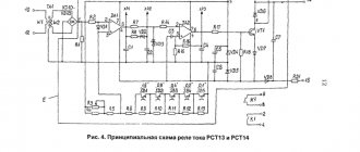
The principle of implementation of the RNT relay
Transformer differential protection
Differential protection is installed in high-voltage dry transformers with a power of no more than 5MVA with switches and controllers for protection against short circuits and overvoltages.
Differential protection has a number of advantages:
- It is possible to detect a malfunction in the TMG insulating oil,
- The differential relay immediately reacts to any damage to the circuits, depending on their classification.
- These protective devices can independently detect almost all errors.
Differential relays have the simplest operating principle and are installed directly in the transformer cabinet. Relays compare the primary and secondary current, and in case of imbalance, protection is triggered.
Transformer protection as a whole is based on monitoring the inequality of various nominal indicators: oil level, current, network voltage, etc.
Handbook for setting up secondary circuits - Checking and setting up DZT-11 series relays
Page 22 of 58
Checking and adjusting differential relays with magnetic braking of the DZT-11 series Unlike RNT, relays of the DZT series do not have a short-circuited winding, which somewhat worsens the detuning from unbalance currents in the presence of an aperiodic component. Checking the executive body is carried out similarly to the RNT series relays. Checking the absence of mutual induction between the brake and secondary windings of intermediate transformers. The check is carried out on the working taps of the brake winding according to the diagram in Fig. 4.11. Jumper 11-12 (not shown in the figure) in the actuator circuit is removed. By supplying current to each brake winding in turn, measure the voltage on the secondary winding of the intermediate transformers with a voltmeter with Rin>1000 Ohm/V. The measured voltage should not exceed 0.1 V at FT = /Ta)T = 200 A. Checking the MMF and primary operating current. The magnetomotive force of operation is checked for each protection arm at selected design turns on all used windings. In the absence of current in the brake windings, the discrepancy between the MMF response in different protection arms should not exceed 1-2%.
Rice. 4.11. Scheme for checking the absence of mutual induction between the brake and secondary windings Fig. 4.10. Characteristics of detuning of RNT series relays from current surges with an aperiodic component
The triggering current is adjusted by changing R in the secondary winding circuit. The relay return coefficient, measured by the primary current, should be in the range of 0.65-0.85. The relay operation currents for any protection arm should not differ from the specified ones by more than 5%: Based on the measured currents, the maximum value is calculated; balance of the operating current, %, for the relay having the largest spread i where /ur is the operating current of one protection arm; /gsr is the operating current of the other protection arm. j The obtained result is compared with the calculated value of the unbalance, %, for the same protection arms. The values of n and m must satisfy the following conditions /r<4 and m<4%; t—/r<4 °/o, where n is substituted into the formula taking into account the sign obtained during the calculation. After setting the operating currents, the absence of vibration of the relay contacts is checked when one of the operating windings is powered with a current from 1.05 /Cr to the maximum possible short-circuit current in this protection arm. The reliability factor must be within the range: kB2—1.2-4-1.3; kBS= 1.35h-1.5. When the braking and working windings are connected in series, kB2 and kBS maintain the specified limits if the ratio of the braking and working turns included in the protection arm does not exceed 0.25: wT/wp<0.25. With a larger ratio, the kB value (especially kni) decreases. Checking braking performance. The maximum braking effect occurs when the phase shift angle between the currents in the braking and working windings is equal to zero or 180°. The resulting braking characteristic must be located below the upper limit characteristic guaranteed by the factory (Fig. 4.12). Rice. 4.12. Braking characteristics of the DZT-11 series relay: 1 - at the angle between the current vectors in the working and braking windings a=0±30°; 2—at a—90±30°; A - response zone; B - braking zone; B - actuation or braking zone Fig. 4.13. Circuit for checking the braking characteristics of the DZT-11 series relay at the angle between the currents /P and 1t equal to zero
Checking the reliability coefficient. The reliability coefficient is determined in the absence of braking and in its presence according to the method given for the RNT relay. characteristics on the brake and working windings, the calculated number of turns is set. The jumper between these windings is removed to ensure independent regulation of the braking and operating currents. Current is supplied to the brake and operating windings from the same phases of the supply network (Fig. 4.13). When the current in the brake winding changes in steps from zero to the maximum short-circuit current, the operating currents are measured. The resulting characteristic is plotted on the MDS scale. The angle between the currents is monitored using a phase meter or VAF-85. If the angles between the currents deviate by more than 10-15°, the characteristic can be taken with identical turns installed on the working and brake windings. Differences in angles are possible due to different ratios of active and inductive resistances of the windings.
Rice. 4.14. Scheme for checking the braking characteristics of the DZT-11 series relay at an angle between the currents /P and /t equal to 90°. The minimum braking effect is checked at an angle between the operating and braking currents equal to 90-120°. Obtaining such a shift is possible by regulating the currents in the working and braking windings from different supply voltages (Fig. 4.14). If the circuit does not provide angle stability within the range of 75-135°, then it is necessary to select power from other phases of the network or proceed to taking the characteristics with maximum turns on the brake and working windings. The resulting braking characteristic must be located above the lower limit characteristic guaranteed by the factory (see Fig. 4.12). Additional checks: a) determining the relay response time is similar to checking the RNT series relays; b) checking the absence of mutual induction between the brake and secondary windings of intermediate transformers, carried out according to the diagram in Fig. 4.11 does not reveal a slight difference in the number of turns of the brake windings of the left and right rods. To identify such a defect, current is supplied to one of the working windings, the jumper is removed between the winding of the executive relay and the secondary winding of the intermediate transformer, and the brake winding is disconnected from the test circuit. In the working winding, such a current is selected to provide a convenient reading of the voltage using a voltmeter, alternately connected to the brake windings of the left and right rods. The measured values should not differ from each other by more than 5%. If there are large differences, it is necessary to achieve their equality by switching branches. If voltage equality cannot be achieved, the relay is rejected. Voltage measurements are carried out with a voltmeter with Rin>2000 Ohm/V; c) determining the operating point on the relay magnetization curve is necessary when the reliability coefficient differs significantly from the factory data. The magnetization characteristic of intermediate transformers is measured by supplying current to one of the working windings and using the executive relay as an indicator. To do this, mark the indicator positions on the relay scale corresponding to 60, 80, 100, 120, 135% of the primary relay operating current. Then the executive relay is disconnected from the intermediate transformers and its operating voltage is determined for each of the above indicator positions. After constructing the magnetization characteristic of the relay (the dependence of the voltage on the secondary winding of the intermediate transformer on the primary current), the operating point is determined from it, which should be located at the very beginning of the bend. If this condition is not met, the relay is rejected. During this check, the relay response voltage must correspond to the manufacturer’s data (3.5-3.6 V); d) checking the relay consumption is necessary to determine the load on current transformers during a short circuit in the protection zone and outside the protection zone. At the same time, the decisive test is to determine the consumption during a short circuit outside the zone, since the load on the current transformers in this mode should not exceed the permissible limit so that there is no false operation due to the large unbalance current. Due to the fact that the consumption of windings during a short circuit outside the zone is always less than the consumption of the same windings in the single-sided power supply mode (with a series connection of the brake and working windings), it is advisable to determine the winding consumption and the load on the current transformers for the single-sided power supply mode. The characteristic is removed up to the maximum short-circuit current in a given protection arm. Based on the results obtained, current transformers are checked for permissible load.
- Back
- Forward
Types of protections and their essence
All protections for transformers must be fast enough to turn off the dangerous mode in time. Since when extremely large electrical quantities occur, it will easily lead to destruction of insulation, metal release, fires and other unpleasant consequences.
To prevent overloads, one or another type of protection is installed on the transformer. What kind of protection is used at step-down substations and in switchgear equipment is determined by local conditions and operating conditions.
Longitudinal differential protection
The scope of differential current protection covers both the power transformer itself and the connections surrounding it, right down to current load meters. The normal operating mode of each transformer is considered to be a uniform redistribution of the load between all three phases, when the electric current in each of them is approximately the same.
Longitudinal differential protection compares the current load in all phases. Since the current is approximately the same, their geometric sum should be equal to zero. As a result of the comparison, it turns out that the current component is absent or too small for the reaction. But, as soon as a short circuit occurs in one phase or between several at once, the currents in them will no longer compensate each other, and their sum will differ from zero, and a differential cutoff will work.
Rice. 3. Example of differential protection
Relay
To prevent damage to transformers, a fairly large number of relay protections are used. However, the oil level control relay deserves special attention. This type provides for monitoring the state of the insulating environment. Structurally, the relay is a float with contacts, which is held above the contacts of the actuation circuit.
If the emergency mode leads to an oil leak and a subsequent decrease below the norm, after which a breakdown may occur, a shutdown will occur. It can be located in the main tank or have backup relay protection in the expander, which will pre-signal the start of the process.
Thermal
The basis for thermal protection in transformers is a classic thermocouple. Its location is determined by the type of device, its power and dimensions, since overheating can lead to a violation of the insulating properties and lead to thermal expansion of the oil.
The most effective placements include:
- at the top of the tank;
- at high-voltage bushings;
- in the windings.
It has two stages - the first turns on backup fans or other cooling means. The second, if the first failed to reduce the overheating below the limit value, turns off the transformer.
Current cut-off
This type of protection is used to disconnect damage that could occur inside the transformer. It is located on the input side of the protected transformer, but the impact covers all windings from which voltage can be supplied. A special feature of its application is the power supply circuit that is used in the corresponding line.
So for three-phase circuits with an isolated neutral, the current cutoff should be installed in two phases. And when using circuits with a solidly grounded neutral, protection must be applied in each phase connection. When the transformer is turned off, there is no time delay at all.
The disadvantage of cutoff is that it only operates on high currents. Therefore, some phase-to-phase, turn-to-turn or ground faults in an isolated neutral circuit may go undetected. In practice, this is one of the simplest ways to turn off a transformer in emergency mode.
Gas protection
Gas relays, as a type of protection, have found wide application in oil-filled transformers, where transformer oil plays the role of a dielectric separating current-carrying elements and the grounded structure of the housing. During normal operation, step-down transformers do not affect the liquid dielectric, and the oil remains in a constant physical state.
But, in the event of interturn short circuits, contact of conductors with steel, or other situations inside the tank, arc burning or heating of the metal leads to local boiling of the oil. From this place the release of gases begins, which rise to the top point of the container.