Updated: 04/23/2021 12:51:22
Expert: Konstantin Borisovich Polyakov
When designing electrical networks of various levels of complexity (including not only the number of end consumers, but their electrical characteristics), developers are faced with the need to automate the opening and closing of the circuit. Fortunately, there is no shortage of suitable devices. On the market you can find dozens of models of relays and contacts, designed for both low- and high-current systems.
But therein lies the problem. It is not always obvious which specific device for opening or closing the electrical network is best to use. And if everything is clear in terms of electrical parameters, the principle of operation is not so obvious.
And therefore, in this material we will look at how a relay differs from a contactor, the features of their use and the fundamental differences between the two categories of devices.
Features of networks with different inductance levels
One of the most important problems that need to be solved when designing electrical networks is arc discharges on key contacts. They can occur even at home - for example, when you plug in a low-quality charger for a smartphone or laptop, you can see a tiny short-term flash. This is called an arc discharge.
Arc discharges (electric arcs) are characterized by significant voltage due to the potential difference on the sides. In this case, the current strength can be quite insignificant. For example, arc discharges can be observed when combing long hair with combs made of synthetic materials - and the “sparks” that escape are definitely not capable of killing a person. Moreover, their voltage can be tens of thousands of volts.
Electric arcs that occur at the contacts of keys (switches, relays, even sockets) have a similar nature, but are much more destructive. Because they instantly raise the temperature of the surface on which they occur, they can simply melt the metal. In fact, that is why they are used in welding.
In addition, according to the Joule-Lenz law, when an electric arc occurs, the current strength increases significantly. Essentially, there is something like a short circuit, but it does not (in the short term) cause damage to devices or the circuit.
In alternating current networks, arc discharges occur primarily due to induction. More precisely, when connecting end consumers with significant inductance. This is due to several physical laws, including even the formation of reactive currents.
In electrical networks in which end consumers with a high level of inductance are installed, the use of relays is impractical and even dangerous. The classic mechanism of this key simply involves connecting two contacts to form a circuit - by time, by command, by temperature or due to other external factors, depending on the type and purpose of the device. But, in any case, such a switching mechanism leads to the formation of an arc. And it, in turn, is characterized by a high danger for the relay itself.
When is it appropriate to use a relay?
Do not think that classic relays are intended for use exclusively in low-current (domestic or some industrial) lines. These devices perform well in various conditions. For example, in aviation, relays are often used that switch direct electric currents with a power of hundreds of amperes.
The main feature of these electromechanical devices is that they are not designed for arc discharge. Their contacts can be physically damaged when this effect occurs, which leads to loss of functionality and other negative consequences - up to a short circuit or destruction of the final equipment.
Relays are well suited for switching secondary circuits that include end consumers with low inductance. For example, lamps and lighting systems, alarms, low-power electrical appliances. It is ideal if the connected equipment, in principle, does not contain electric motors or other functional elements characterized by a significant level of induction.
At the same time, voltage and current do not matter. There are low-current relays, used for use in household networks, and high-current, focused on switching direct electric currents with a large number of amperes. The main thing is precisely the question of induction and, as a consequence, the formation of “sparks”.
By the way, power supplies that convert alternating current into direct current with a decrease in voltage and power are devices with relatively significant induction. Therefore, it is better not to use a relay to switch them. And because of this, they sometimes “spark” when plugged into an outlet.
Classification of contactors
By type of applied voltage:
- Constant voltage.
- Variable voltage.
By the type of current in the secondary circuit:
- Direct current.
- Alternating current.
By the number of switched poles:
- One pole.
- Two poles, etc.
Based on the presence of an arc extinguishing device:
- There is a suppression device.
- Absent.
When a device is triggered, impulses appear in the network that have a harmful effect on other systems receiving power from the same network, and radio interference also occurs. Nearby devices may not operate properly under these conditions. To eliminate this effect, some types of contactors are equipped with a protection system against self-generated interference.
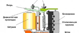
The principle of operation of the contactor: an electrical current is supplied to the coil, which creates an electromagnetic field that magnetizes the core.
When large loads of an inductive nature are turned on using a contactor, an electric arc occurs between its contacts, leading to burning of the active substance on the switching plates. Typically, silver is used to improve performance at the junction. It has a fairly high price and in case of burnout leads to additional costs for restoration or replacement.
In order to eliminate this drawback, contactors are equipped with additional devices that can extinguish the electric arc that occurs during connection. Contactors are capable of connecting loads with very high voltage and current.
When is it appropriate to use contactors?
Contactors are designed for switching alternating current networks into which consumers with high inductance are connected. They are not resistant to arc discharge, but try in every possible way to avoid its occurrence. To do this, they are equipped with additional protective components of various types, one or more:
- Arcing chambers. These are special grilles that neutralize “sparks”. The arc, passing between the metal plates, increases its length - and thereby cools down until it is completely extinguished;
- Mechanically moving contacts suitable for active switching. Most contactors for domestic and industrial use are oriented at switching frequencies from 30 to 3600 actions (on-off cycles) per hour;
- Separate control circuit. An auxiliary electric current circulates in it, having a significantly lower voltage than in the main one.
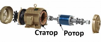
Thanks to all these design and technological features, contactors are suitable for controlling networks with connected consumers of significant inductance - from household equipment with electric motors (refrigerators, washing machines, fans) to industrial machines.
In addition, it is worth noting that equipment with electric motors tend to consume significantly higher currents at start-up than during operation. When the engine starts, the power spikes - as does the power (in amperes) - which overloads the line. Often relays designed for use in low-current networks cannot withstand such overloads. There are no such problems with contactors.
Similarly, you should not think that a contactor is a device for use in high-current networks. There are models aimed at domestic use. For example, on the market you can find contactors rated for a nominal voltage of 230 volts and a current of 10 amperes. In this case, their coils are connected to the 110-volt auxiliary circuits.
What is the difference between a contactor and a starter?
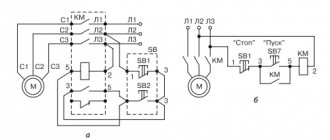
In fact, a contactor is a device consisting only of an electromagnetic coil and contacts. When voltage is applied to the coil, the contacts close (or open). The contactor does not contain devices for protection, fixation, switching, indication, etc. A starter is a device that contains a contactor as the main component element. In addition, the starter usually contains a thermal relay for protection against overcurrent, START and STOP buttons, an indication, can be enclosed in a housing, and have a circuit breaker for short-circuit protection. In other words, the starter is used to start (turn on) various electricity consumers.
More details about the purpose and design of the contactor are described in the video:
Details on how a three-phase electric motor is connected to a starter and various circuits for connecting an electric motor are given in my article on connecting asynchronous motors. And another example of using starters is in the article about the hydraulic press circuit. Various schemes for switching on magnetic starters are discussed in detail here.
And if you are at all interested in what I write about, subscribe to receive new articles and join the group on VK!
The starter may contain two or three contactors. This happens in cases where reversible engine control , or during soft start , when a powerful engine is turned on first in a star circuit and then in a delta circuit.
Although such a scheme cannot be called “smooth”, there are special devices for smooth starting. Read my articles about the Soft Starter and about the Real Circuit for Switching on a Soft Starter.
Disassembled starter PML-1220 0*2B. The contactor and thermal relay are visible.
Officially, the differences between a contactor and a starter are specified in GOST R 50030.4.1-2012
(IEC 60947-4-1:2009) Low voltage distribution and control equipment. Part 4. Contactors and starters. Section 1. Electromechanical contactors and starters.
From this GOST we can conclude that the motor protection circuit breaker, star-delta circuit, soft starter and frequency converter are also starters!
More definitions of contactors and starters are given in GOST 17703-72 “Electrical switching devices. Basic concepts” and GOST R 500030.4.4-2012 “Low-voltage distribution and control equipment”.
It will also be interesting what huge debates flared up on my Yandex.Zen channel in an article about the differences between contactors and starters.
Comparison of relays and contactors
So, let’s summarize by comparing these two types of devices for switching electrical networks.
| Characteristic | Relay | Contactor |
| Arc protection | No | Yes |
| Use in circuits with consumers with high inductance | No | Yes |
| Application in high-current electrical networks | Mainly at constant current | Yes |
| Application in low-current electrical networks | Yes | Yes |
| Design Features | No | Equipped with arc chutes and/or other arc flash protection solutions |
| Main areas of use | Switching of low-current systems - lighting, alarm | Switching systems with high inductance equipment - in production and in workshops |
If you plan to connect equipment that consumes high currents at startup or is characterized by high inductance and/or the creation of reactive voltage during operation, it is advisable to use contactors. In other cases, a relay will suffice.
Electromagnetic relays
Just like contactors, relays - devices for switching in automatic electrical circuits - are divided into types according to different factors.
By area of application:
- for automated systems;
- for protective systems;
- for systems management.
By type of incoming parameter:
- current control relay;
- voltage control relay;
- power control relay;
- frequency control relay.
Based on the operating principle:
- electromagnetic;
- thermal;
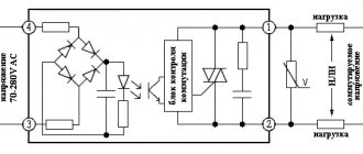
- semiconductor and so on.
By impact on the controlled part:
- contact;
- contactless.
By type of control voltage:
- AC relay;
- DC relay.
Modern electromagnetic modular relays are subject to great demands: they must be reliable and highly sensitive, have fast response and selectivity. Selectivity is important because in case of accidents, the relay is able to leave intact elements in operation, turning off damaged ones.
