First mention of a relay
The invention cannot be attributed to just one scientist. Since this issue is still controversial. Some believe that the discoverer was the Russian scientist P. L. Shilling, who designed the relay in the 1830s. It was the main element in the telegraph, created by him.
Others claim that the relay's first creator was physicist Joseph Henry. In 1835 he began to improve the telegraph apparatus he had created in 1831. And for this he invented a contact relay, which worked based on the principle of electromagnetic induction. At that time the device was non-switching. In 1837, relays began to be produced in large quantities.
As a separate device, the relay was mentioned in a patent for a telegraph apparatus, which was issued to Samuel Morse in 1837.
The relay was originally a telegraph device. In the modern world, almost every equipment, appliance, household appliance, car, etc. has a relay device.
How to test an electromagnetic relay
The performance of an electromagnetic relay depends on the coil. Therefore, first of all, we check the winding. They call her a multimeter. The winding resistance can be either 20-40 Ohms or several kOhms. When measuring, simply select the appropriate range. If there is data on what the resistance value should be, we compare. Otherwise, we are content with the fact that there is no short circuit or break (the resistance tends to infinity).
You can check the electromagnetic relay using a tester/multimeter
The second point is whether the contacts switch or not and how well the contact pads fit. This is a little more difficult to verify. A power source can be connected to the output of one of the contacts. For example, a simple battery. When the relay is triggered, the potential must appear on the other contact or disappear. This depends on the type of contact group being tested. You can also monitor the presence of power using a multimeter, but it will need to be switched to the appropriate mode (voltage control is easier).
If you don't have a multimeter
You don't always have a multimeter at hand, but you almost always have batteries. Let's look at an example. There is some kind of relay in a sealed housing. If you know or have found its type, you can look at the characteristics by name. If the data is not found or there is no relay name, look at the body. Usually all important information is indicated here. The supply voltage and switched currents/voltages are required.
Checking the electromagnetic relay winding
In this case, we have a relay that operates from 12 V DC. It’s good if there is such a power source, then we’ll use it. If not, we assemble several batteries (sequentially, that is, one after another) in order to obtain the required voltage in total.
When batteries are connected in series, their voltage is summed up
Having received a power source of the required rating, we connect it to the coil terminals. How to determine where the coil terminals are? Usually they are signed. In any case, there are symbols “+” and “-” for connecting constant power sources and signs for an alternating type such as “≈”. We supply power to the corresponding contacts. What's happening? If the relay coil is working, a click is heard - this is the anchor being pulled. When the voltage is removed it is heard again.
Checking contacts
But clicks are one thing. This means that the coil is working, but you still need to check the contacts. Perhaps they have oxidized, the circuit closes, but the voltage drops significantly. Maybe they have worn out and the contact is poor, or maybe, on the contrary, they have boiled and do not open. In general, to fully test the electromagnetic relay, it is also necessary to check the functionality of the contact groups.
The easiest way to explain is using a relay with one group as an example. They are usually found in cars. Car enthusiasts call them by the number of pins: 4 pins or 5 pins. In both cases there is only one group. Simply, a four-contact relay contains a normally closed or normally open contact, and a five-contact relay contains a switching group (changeover contacts).
Electromagnetic relay 4 and 5 pins: contact location, connection diagram
As you can see, power is supplied in any case to the pins labeled 85 and 86. And the load is connected to the rest. To test a 4-pin relay, you can assemble a simple combination of a small light bulb and a battery of the required rating. Screw the ends of this bundle to the contact terminals. In a 4-pin relay these are pins 30 and 87. What happens? If the contact is closed (normally open), when the relay is activated, the light should light up. If the group opens (normally closed) it should go out.
In the case of a 5-pin relay, the circuit will be a little more complicated. Here you will need two bundles of a light bulb and a battery. Use lamps of different formats, colors, or somehow separate them. If there is no power to the coil, you should have one light on. When a relay is activated, it goes out and another one lights up.
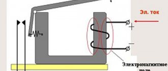
How it works and how it works
Today, a relay looks like this: it is a coil with a wire wound around it. This wire is made of copper and is usually coated with a varnish with dielectric properties. It may also have fabric or synthetic insulation. The coil has a metal core that sits on a base that does not conduct current. In addition, the relay contains various connecting elements, contacts, an armature and springs.
The principle of operation of the relay is as follows. When current is applied to the coil, its core begins to attract the armature. Then it connects to the contact and the circuit is closed. When the current strength becomes lower, it opens, i.e. the armature will return to its original position with the help of a spring.
To make the device work more accurately, resistors are used for this. There is also a need to install capacitors. They will protect the relay from voltage surges.
For more productive operation of the device, in order to control several circuits at once, several pairs of contacts are installed in the electromagnetic relay.
Voltage relay connection diagram: step-by-step instructions
Here we will look at the process of connecting the device with other elements of the electrical panel. In addition, you will need to prepare the following:
- voltage switch;
- conductors with a cross section of up to 6 millimeters;
- mounting rail for installing other automation;
- self-tapping screws
The equipment connection diagram looks like this:
Step 1: turn off the automation and unscrew the plugs.
We fix the mounting plate with self-tapping screws
Step 2: fix the voltage switch to the bar using fasteners located in the back of the case.
Fixing the device
Step 3: using a special tester, you need to detect the phase on the contacts of the circuit breakers.
We check the phase contacts with an indicator
Prices for different types of multimeters
Multimeter
Step 4: Next you need to make a cut in the wiring that extends from the main circuit breaker into the apartment.
Making a wiring cut
Step 5: Next, the remaining end of the wire from the circuit breaker must be connected to the voltage relay at the input contact.
Connect the wire to the relay
Step 6: The other end of the conductor after cutting should be connected to the output terminal.
Connect the conductor to the output contact
Step 7: Next, the piece of wire must be connected to the neutral conductor on the machine. In modern panels, the connection is made to the zero bus.
You can read about how to properly connect circuit breakers in an electrical panel in our special article.
Connect a piece of wire to the neutral
Step 8: The remaining end must be connected to the neutral terminal of the switch.
Then all you have to do is turn on the power
There is another version of the device that connects to an outlet. In this case, every person can handle the installation process, because the device resembles a standard tee.
Another relay connection diagram
In the image below you can find a diagram for connecting the load relay and the network. So, power must be connected to the first power contact, the load is connected to the second, and the neutral is placed on the other load terminal.
Relay connection diagram
The power section is connected using the method described above. Next, you need to assemble the control line: you need to connect the power supply unit or battery (for a DC relay) to the core. In the case of an AC device, the circuit is practically no different, you just have to apply alternating voltage to the core.
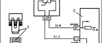
Next, we will look at an example of controlling a relay device for a car's central locking system, where there is control with two fields.
It turns out that in order to set the activator in motion, it is necessary to connect plus and minus to the coil. To return the armature to its place, you will need to change the polarity. This is done using two relays and five contacts.
Connection diagram
When voltage is applied to the left relay, positive is supplied through the lower conductor. Through closed contacts from the right relay, the lower conductor is connected to the negative terminal. If you apply voltage to the right relay core, the polarity will be reversed.
This is a common case when you not only have to turn on the relay to the load, but also create all sorts of connection diagrams with reversals.
Video - How to connect a relay?
Relay characteristics
There are several basic characteristics of relays that are suitable for all devices, regardless of the principle of operation:
- Sensitivity - indicates whether the device will turn on if a current of a certain strength is applied to the winding.
- Resistance arising across the coil winding.
- Triggering current – shows the minimum current value at which the contacts will switch.
- The release current is the value at which the device will turn off, i.e. the electrical circuit will be interrupted.
- The response time is a value that is determined by the amount of time from the arrival of the signal until the moment of impact on the electrical circuit.
- Frequency of relay operation when there is a load on the contacts.
What is a relay
An electromagnetic relay is a switching device that can connect or break an electrical circuit when the incoming current changes abruptly. In simpler terms, we can say that the relay works like an ordinary switch that can be used to turn on or off the light in a room. But instead of a hand pressing a lever, it is triggered by an electromagnetic pulse.
True, the signal for action may not always be of an electrical nature. But other types of relays are responsible for the operation of such systems:
- In a photo relay, it is triggered by a flash of light.
- The audio signal closes to a loud bang or knock.
- In a time relay, a circuit break or connection will occur after a precisely counted time interval.
- The temperature will work after the temperature sensor marks the specified parameters.
The real meaning of the word "relay" has interesting historical roots. This is how the change of post horses was designated in France. Later, this became the name for passing the baton in sports competitions. But the authorship of the invention is controversial.
The first telegraph apparatus Source ic.pics.livejournal.com
See also: Catalog of companies that specialize in electrical work of any complexity
Some attribute the discovery to the Russian scientist Schilling. Others argue that the ancestor is George Henry, a native of America. Only one thing is known for certain. The first device to use the electromagnetic principle was the telegraph, which was patented by Samuel Morse in 1937.
Advantages of electromagnetic relays over semiconductor counterparts:
- Ability to switch electrical networks up to 4 kW while maintaining small dimensions.
- Resistance to interference, as well as overvoltage, which is common in high-voltage equipment.
- The insulation of the electromagnetic relay is highly reliable, which creates additional safety.
- The heat generated during operation of the device is insignificant.
But relay electromagnetic mechanisms do not cope well with inductive loads when high-voltage currents are switched. And when contacts are triggered, electromagnetic interference is often created. In addition, the relay has extremely limited electromechanical functionality and low operating speed.
Electromagnetic time relay Source zemit.com.ua
The latter depends on the fact that the current in such a relay, due to the design features, cannot increase or disappear instantly. He needs some time for this.
Classification of switching devices
A relay is a device that has found wide application. It is used not only in various industries, but also in everyday life. For example, in a washing machine or refrigerator.
Since there are many types of switching devices, the classification of relays is quite broad. There are several groups into which relays can be divided.
By area of application
- control of different circuits;
- protection of electrical systems;
- process automation.
According to the operating principle
- thermal;
- electromagnetic;
- semiconductor;
- induction
According to relay operation parameters
Depending on the parameters that trigger the relay, the classification is as follows:
- on current strength;
- from tension;
- from power;
- from frequency;
- from polarity.
By impact on the electrical network of the device
- contact – a short circuit or opening occurs;
- non-contact – current parameters change.
Switch design and operating principle
The most primitive device consists of a core with a winding, a return spring and elements that connect the switch - the base, the frame. When current flows, the electromagnet is triggered, which allows the contact to be connected to the armature. Such actions close the electrical circuit.
If the current supply stops or is reduced to a minimum, the return spring moves the armature into place, thereby opening the circuit. In addition to the main components, the new devices include a resistor to ensure smooth operation and a capacitor to prevent the consequences of voltage fluctuations.
Elements of an electromagnetic relay
Thus, chains that are connected using a switch are called controlled, and the signal input line is called control. Typically, relay connections provide additional reinforcement because they complete high-power circuits by applying minimal voltage.
The operating principle of the devices also depends on the type, because some of them are designed for alternating current, while others are for direct current. AC switches are triggered by the frequency of the signal. DC devices operate in the following situations:
- Magnetoelectric - show sensitivity to the polarity of the current, depending on whether it is supplied to the positive or negative contact. In this case, the moving element is deflected to the sides.
- Neutral - even when the current moves in two directions, the armature oscillates in one direction.
Types of relays and where they are used
A relay produced today immediately has such settings that it is triggered when a certain situation occurs. For example, if the voltage increases. Let's look at what types of switching devices there are and what triggers them.
Electromagnetic relay
The principle of operation is that a magnetic field arises around the coil, under the influence of current, and it actuates the armature. Switching devices of this type are divided into neutral and polarized. Neutral react only to the amount of current supplied to the coil winding. Polarized - react not only to the size of the current, but also to the polarity. This relay is mainly used in control circuits.
AC Relay
In this type of device, the relay begins to operate if the winding is exposed to alternating current with different frequencies. The switching device consists of modules based on transformer isolation. These relays are used where there are AC networks whose maximum voltage is low. This device is used in household appliances and machines.
DC relay
These devices are divided into two types:
Neutral - do not depend on the polarity of the voltage.
Polarized - depending on the polarity of the voltage supplied to the winding, the armature changes its direction.
It is used when it is not possible to connect an AC relay to the electrical network. It is used in various industries to control automation.
Electronic relay
According to the principle of operation, this relay is almost exactly the same as an electromechanical device, but to perform some actions, it uses a semiconductor diode. This type of relay is used in vehicles and installations with increased power loads.
Main performance characteristics
Industrial relay 24V
So, an AC relay is an intermediate element that drives a controlled electrical circuit.
This device has the following parameters:
- Actuation power (P cf - measured in Watts) is the minimum power current that must be supplied to the relay for its normal activation. Nominally, this parameter is selected according to the general design and electrical parameters of the relay.
- Control power (P control - measured in Watts) is the maximum current power that a relay can transmit in a switched network. This value is determined by the parameters of the relay working contacts.
Advice! It is not difficult to guess that when choosing a relay for a network, they are guided by the named parameters, which are constant for certain designs.
- Response time (T cf - measured in seconds) is the time difference from the moment the signal arrives at the control contact until the contacts close or open.
- Permissible breaking power (Pr - measured in Watts) - this parameter can be found in high-current relays. It denotes the power at a certain current, which, if broken, will not allow the creation of a stable electric arc.
How does a relay work?
Diagram of relay operation over time
The control circuit and the relay itself are characterized by some inertia, which is why the input current to the relay does not increase and decrease instantly, but varies within certain limits over time, which is clearly visible in the diagram shown above, from which it is also clear that the duty cycle consists of three stages:
- Trigger;
- Job;
- Return.
Let's take an electromagnetic DC relay as an example to understand the basic principles.
Back to the Future: Relay from 1983
- Inside such a relay there is an inductance coil, due to which a gradual change in current parameters occurs. The relay operation itself for each stage consists of certain time periods.
- Triggering – has two such intervals: starting time (ttr) and time for armature movement (tdv). That is, T av = ttr + tdv - everything is simple.
- Work is also two sections, which are indicated on the time line by segments AB and BC. In the first stage, the current continues to increase for some time until the set value is reached, which allows for reliable attraction between the armature and the core, preventing vibration of the armature. In the second section, no changes in the current value occur.
- Return – similar, 2 sections. At the first, the relay is released, and at the second, it returns to its original state. Throughout the entire period, the current strength decreases.
Three Phase AC Relay
Other characteristics
In addition to the above, different types of relays have the following parameters:
- Return coefficient (Kb) – the ratio of the releasing current to the triggering current. Typically this value varies from 0.4 to 0.8. Calculated using the formula: Iot/Iav < 1.
- The safety factor (Krep) is the ratio of the steady-state current (I set), that is, the maximum, to the operation current. This value shows how reliable the selected device is.
- The last parameter is called the control coefficient (K control) and is represented by the ratio of control power to actuation power. That is, if the relay is used as an amplifier, then we see the coefficient of this amplification.
How is a relay indicated on the diagram?
To repair equipment in which a switching device is installed, you should know what it looks like in the diagram.
So, the coil winding in the diagram is a rectangle from which contacts emerge: A1 and A2. The relay itself is signed with the letter K.
The polarized relay in the diagram is also a rectangle, only with a large black dot on one of the contacts. Such a relay is designated by the letter R.
These are the main designations of the device on the diagram. For more detailed information on other types of images, see the electronics reference book.
Briefly about the main thing
When thinking about good and reliable protection of the electrical circuit, you should pay attention to electromagnetic relays. They can withstand network overvoltage and do not respond to interference. Capable of providing reliable switching on high-power lines. And at the same time maintain its small dimensions.
They have the simplest operating principle, based on creating a magnetic field in a circuit. The latter is responsible for breaking the line in case of danger or for connecting when controlling and adjusting the object. And when choosing between alternating and direct current to operate the device, it is better to choose the latter. If you choose the first, you will have to look for ways to neutralize the strong vibration of the core in the induction coil.
Major manufacturers of relay devices
Finder is a relay manufacturer from Germany. They produce the following types of relays: general purpose, time relay, power, interface, etc.
Joint-stock company NPK "Northern Zarya" - production from Russia. Manufactured products: contact and non-contact time relays, electromagnetic devices, etc.
Omron is a company from Japan. Produces the following relays: electromechanical relays, switches, low-voltage and solid-state devices.
Cosmo Electronics is a Taiwanese switching device company. The produced relay has found its application in industry, medical equipment, as well as household appliances and automobiles.
American Zettler is a leader in the production of relays. The products manufactured by this company are used in all areas of activity. They have established the production of more than 30 types of switching devices.
Application
Solid state relays are used to control electronic devices, equipment and automatic systems connected to an electrical network with a power of 20 to 480 watts.
Used in various fields:
- automation of industrial processes;
- various household installations;
- heat regulation systems in heating elements;
- in lighting control systems and motion sensors;
- car electronics.
The relay is found in refrigerators, kettles, washing machines, heating elements, and uninterruptible power supplies.
The areas of use of solid-state devices depend on their design, connection diagrams and other operating conditions.
TSRs do not require constant maintenance and can be installed in any hard-to-reach places.
The popularity of solid-state devices is increasing every day, thanks to widespread automation.
SSR connection
When connecting the relay, polarity must be strictly observed.
Voltage is supplied to the control inputs. Loads are connected to the output terminals. Connections are made using screw connections (no soldering).
When connecting voltage, make sure that the switching is carried out correctly.
It is not allowed to place devices near flammable materials.
The relay housing may become hot during operation. When the temperature rises above 60°C, install the SSR through a cooling radiator.
Connection diagram
Selecting a Solid State Relay
The overload properties of SSRs that switch alternating current are significantly higher than those of devices that switch direct current.
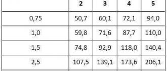
Table 2. Relay overload capacity.
| Current type | Permissible maximum overload (Ampere) during 10 ms. | ||
| Constant | 90 | 250 | 380 |
| Variable | 120 | 300 | 410 |
When choosing, you need to consider the following aspects:
Switching methods
The most popular devices are those in which control is performed when passing through “0”.
This type of switching is suitable for resistive type loads. The method allows you to eliminate interference created when turned on.
Phase control
The phase method is used in resistive lighting control circuits, transformers, and infrared emitters.
The regulation process in phase control is smooth and seamless. The disadvantage of this method is the appearance of interference during switching.
Phase controlled relay.
A relay with a phase regulator can be recognized by its symbol on the body, in the area where the input terminals are located.
Parameters and types of loads
Load current is one of the most important parameters when choosing a relay.
For reliable operation, choose a relay with a reserve:
- 30-40% - with active load (heaters);
- 6-10% - for asynchronous electric motors;
- 8-12% - for incandescent lamps;
- 4-10% - for electromagnetic relay coils.
Particular attention is paid to the following parameters:
| 1. Load current limit | ranging from 10 to 500 amperes |
| 2. Switchable voltage level |
|
| 3. Control signal |
|
To connect an inductive load (for example, an electric motor), it is necessary to take into account the starting current, which exceeds the rated current by 600-100%
Availability of cooling
The reliability of solid-state relays depends on its operating temperature.
The temperature should not be allowed to exceed 60°C.
The temperature regime of the relay is influenced by various factors:
- ambient temperature;
- installation location;
- existing loads;
- presence of air circulation.
When using relays at high currents, excess heat should be removed to cooling radiators, fans or other cooling options should be provided.
When heated, for every 10°C the throughput of the device decreases by 20-25%. When solid-state relays heat up to 80°, the product fails.
Protection
There are various options for protecting solid state relays:
- RC circuit - against false triggering when operating on an inductive load.
- Varistors - for protection against short-term voltage surges on the load side. Devices are selected taking into account the value of the switching voltage (from 1.6 to 2).
- Semiconductor fuses - provide overload protection. It should be taken into account that the device current is up to 30% of the rated current.
- Shunt resistors mounted in parallel to the load ensure correct operation at low currents.
Operating principle
To understand the operating principle of solid-state relays, you need to know their design features.
The interaction of the controlled and control signal is ensured by galvanic or optical isolation.
One of the main elements of the SSR is an opto-isolator, or optocoupler in the form of an LED and a photosensitive device that isolates the input from the output.
When electricity passes through the LED connected to the input section of the solid state relay, it lights up. Focusing through the gap, the light is transmitted to a photosensitive transistor or semistor.
The principle of operation of the device is to close and open contacts that transmit voltage.
The circuitry of all solid-state devices is approximately the same. Minor differences between different models do not affect its functionality at all.
The mechanism works by closing and opening the contact terminals that transmit voltage.
Advantages and disadvantages
The advantages of solid-state models include:
- absence of noise and vibration;
- compact dimensions;
- wide scope of application;
- instantaneous switching speed (thousandths of milliseconds);
- no electromagnetic interference when turned on;
- long service life due to the absence of moving parts;
- constant output resistance throughout the entire service life;
- minimal electrical energy consumption;
- possibility of load regulation;
- low sensitivity to vibrations, high humidity, dust, and magnetic fields.
The switching life of solid-state relays is a thousand or more times higher than that of electromagnetic analogues.
When operating such devices, the possibility of sparks occurring during switching is eliminated, which allows the devices to be used in explosion- and fire-hazardous facilities.
The main disadvantages of solid-state relays:
- heating of the device due to high resistance in the pn junction circuit;
- frequent false alarms during power surges;
- the possibility of failure of the power switch due to overloads and short circuits;
- high price.
The SSR has a leakage current, due to which the phase wire may be energized even when the relay is turned off.
Devices designed to operate in direct current conditions require strict adherence to polarity when connecting output circuits.
Solid state relays are periodically checked for package integrity and insulation.