Special devices—temperature sensors—help control the degree of heating of any object, regardless of its physical state. Their operating principles and execution may differ significantly. This allows you to choose the best option depending on your goals. Knowing what the device is intended for, it is worth figuring out how to connect the device so that it allows you to take readings with a given accuracy.
Thermocouple
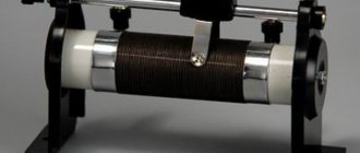
Structurally, a thermocouple consists of soldering two wires of different metals. The temperature difference between the hot and cold ends provokes the appearance of an emf in the circuit, the magnitude of which depends on the material and thermoelectric force of the thermocouple and can be from 40 to 60 μV. Combinations of nickel-chrome, chromium-aluminum, iron-nickel, iron-constantan and others are used as thermocouple materials. The thermocouple provides high accuracy, but measuring this accuracy is problematic. Being a relative sensor, a thermocouple has a voltage level dependent on the temperature difference between the junctions. The cold junction usually has the temperature of the environment in which it is located. If we delve deeper into the principle of operation of a thermocouple, it looks like this: at the hot and cold ends of the thermocouple there are two temperatures, the difference of which determines the emf. The cold junction temperature must be compensated. A solution to this problem in a hardware environment is to use a second thermocouple placed in an environment with a previously known temperature. The software environment uses a different, absolute temperature sensor placed in an isothermal chamber along with the cold junctions. Such a sensor controls the temperature of the junctions with a specified accuracy. When working with a thermocouple, there are a number of difficulties that accompany taking data from the sensor:
- Thermocouple nonlinearity
. To convert the EMF value to temperature and vice versa, high-order polynomials are used, prescribed in GOST - The thermo-EMF values
obtained from a thermocouple are small, on the order of units and hundreds of microvolts, which makes it impossible to use conventional analog-to-digital converters. To obtain undistorted data from the thermocouple, precision multi-bit, low-noise analog-to-digital converters are used
Connection procedure
The temperature sensor connection diagram may differ significantly. It all depends on which variety is preferred. Before proceeding with installation, it is necessary to determine the required accuracy and purpose of the device. If it is to be used to control indoor air temperature, one circuit will be required. If you need to measure the degree of heating of a substance, you will have to use another one.
How to connect silicon
To connect a silicon-type temperature sensor, the following circuit can be used:
- 2-wire. It is relevant in the absence of increased requirements for high accuracy, since in this case the resistance of the connected wires is added to the measured resistance. This significantly increases the amount of additional error;
- 3-wire. Installing a temperature sensor according to this scheme improves accuracy. This connection allows you to measure the resistance of the wires, and then subtract the resulting value from the measured one;
- 4-wire. According to this scheme, the device is connected in such a way as to completely eliminate the influence of the supply wires. This allows you to get rid of additional errors and significantly increase the control accuracy.
How to connect a thermocouple
To connect the cold ends, compensation wires are used or installation is carried out directly to the analog input terminals. In this case, it is important to observe the polarity at the input to the industrial controller used for software compensation of the cold junction temperature and subsequent calculation of the temperature at a given point.
Internal compensation is performed using the temperature of the module used to connect the thermocouple. For accurate external compensation, the temperature of the cold junction is controlled by an additional resistance thermometer connected to a special input.
How to use a contactless device
Non-contact temperature sensors have the ability to determine the degree of heating of the device. In this case, a direct connection is not required. The device approaches the controlled object and its alignment with the corresponding sensor is ensured. This has a significant impact on the final result, which largely depends on the experience and knowledge of the specialist performing the measurements. If we change the contactless device to a contact model, the accuracy will increase.
The diagram provided in the instructions for a specific device indicates the procedure for connecting and subsequent operation of the temperature sensor. Before you begin installation work, you should familiarize yourself with it carefully in order to avoid common mistakes made by inexperienced users when performing installation work on their own.
Thermistors
A simpler and more common device for measuring temperature is thermistors. Their work is based on the principle of dependence of the resistance of materials on external temperature. Metal resistance thermometers, especially platinum ones, provide high accuracy and linearity of measurements. The main characteristic of a resistance thermometer is the base resistance of the thermometer at a certain temperature. According to GOST, resistance at zero degrees Celsius is considered basic. GOST recommends using several resistance values in Ohms and a temperature coefficient, which is determined by the formula: Tc = (Re – R0c)/(Te – T0c)*1/R0c,
Where
Re
is the resistance at our temperature;
R0c
– resistance at zero degrees;
Te
is our temperature;
T0c
– zero temperature. GOST thermistors contains temperature coefficients for various thermometers made of platinum, copper and nickel and polynomial coefficients for calculating temperature from the current resistance of the resistor. Although resistance thermometers have a small temperature coefficient of resistance, it is easier to obtain high accuracy when measuring resistance than when measuring small voltage values when working with a thermocouple. To measure resistance, a thermal resistance is connected to the current source circuit, after which the differential voltage is measured. The temperature coefficient when using semiconductors will be a fraction of a percent. For such measurements, analog-to-digital converters are used. Temperature sensors implemented in the form of integrated circuits are equipped with an analog output corresponding to the supply voltage. To digitize the signal from such sensors, eight- or ten-bit ADCs are used.
Principle of operation
The main function of the DS18B20 chip is to transform the readings of the built-in temperature sensor into a digital code. This conversion depends on the conversion resolution set by the user, which varies from 9 to 12 bits (0.5°–0.625°C). If no settings have been made, the configuration register setting corresponds to 12 bits.
In the initial state, DS18B20 is at rest, or in other words, at a low energy level. To start measurements, the microcontroller sends a signal [0x44], after which the received data is stored in a register, and the sensor itself goes into “rest” mode.
When the DS18B20 digital temperature sensor operates from an independent power source, the microcontroller is able to control the process of executing the command [0x44], which measures the temperature. Thus, the DS18B20 temperature sensor will generate a logical “0” during the transformation of temperature readings and a logical “1” if the conversion process is completed.
If the microcircuit is powered using the “parasitic method”, then control of logical “0” and “1” is impossible, since a high level of supply voltage will constantly be on the bus.
After removing and processing the signal from the temperature sensor in the DS18B20 chip, the received data in degrees Celsius is stored in the form of a 16-bit number with a sign (S), which is responsible for the “+” or “-” sign of temperature. The temperature register structure will look like below.
If the temperature reading is above “0”, then the indicator is S=0, but if the temperature value is negative, then S=1. Below is a table of data and temperature correspondence.
Quartz temperature converters
If it is necessary to expand the range of measured temperatures, quartz converters are used. They allow measurements in the range from -80 to +250 degrees Celsius. The principle of their operation is based on the frequency dependence of quartz on temperature. The function of the converter varies depending on the location of the cut along the crystal axes. Quartz sensors provide high sensitivity and measurement resolution, coupled with operational stability. Due to these properties, quartz sensors are widely used in digital thermometers.
Frame
TSic series sensors are available in SOP-8 and TO92 packages; pinouts are available in the documentation.
In addition, it is possible to supply TSic sensors in non-standard housings, with various types of cables, connectors, contact pads, and so on. Everything here is discussed individually, but I’ll say right away that to use this opportunity it is absolutely not necessary to have a project for hundreds of sensors per year.
Noise temperature sensors
The operation of noise temperature sensors is based on the dependence of the noise potential difference across the resistor on temperature. In practice, to measure temperature with noise sensors, you need to compare the noise of two identical resistors, one of which is located in an environment with a known temperature, the second in an environment whose temperature needs to be measured. The temperature range that can be measured using noise sensors is from -270 to +1100 degrees. The main advantage of noise sensors - the ability to measure temperature in thermodynamics - is complicated by the extremely low noise voltage, comparable to the self-noise level of the amplifier. This makes noise voltage extremely difficult to measure.
Do-it-yourself installation recommendations
Such devices are widely used for various purposes: they are equipped with radiators, heating boilers and other household appliances.
Before starting installation, you should carefully read the instructions: it indicates not only the installation features (for example, dimensions for connecting to the pipe), but also the operating rules, as well as the temperature limits for which the measuring device is suitable.
It is also necessary to take into account the size of the sleeve, which can vary between 120-160 mm.
Let's consider the two most common cases of installing a temperature sensor.
Connecting the device to a radiator
It is not necessary to equip all heating devices with a thermostat. According to the regulations, sensors are installed on the battery if its total power exceeds 50% of the heat generated by similar systems. If there are two heaters in the room, then the thermostat is installed only on one, which has a higher power rating.
The temperature sensor is a mandatory component of temperature controllers that allow you to reduce or increase the heating of radiators, heated floors and other heating devices
The device valve is installed on the supply pipeline at the point where the radiator is connected to the heating network. If it is impossible to insert it into an existing chain, the supply line must be dismantled, which can cause some difficulties.
To carry out this manipulation, you need to use a tool for cutting pipes, while installing a thermal head can be easily done without special equipment. As soon as the sensor is mounted, it is enough to align the marks made on the body and the device, after which the head is fixed with a smooth hand press.
Installation of air temperature sensor
Such a device is installed in the coldest living room without drafts (in the hall, kitchen or boiler room its installation is undesirable, as it can cause disruptions in the operation of the system).
When choosing a location, you need to make sure that the device is not exposed to sunlight, and there should be no heating devices (heaters, radiators, pipes) nearby.
For a conventional heating system, one thermostat is sufficient, while with a collector circuit it is advisable to use several sensors, the number of which coincides with the number of rooms. This will allow you to individually regulate the temperature in separate spaces.
The device is connected according to the instructions contained in the technical data sheet, using the terminals or cable included in the kit.
If it is necessary to monitor the temperature, the temperature sensor in the “warm floor” can be located deep in the concrete screed. In this case, for protection, you can use a corrugated pipe with one closed end and a sloping bend.
The latter feature allows, if necessary, to remove the broken device and replace it with a new one.
Installation of the device is carried out as follows:
- A recess is made in the wall for mounting an attachment.
- The front part is removed from the temperature sensor, after which the device is installed on the prepared area.
- Next, the heating cable is connected to the contacts, while the terminals are connected to the sensors.
The final stage is connecting the power cable and installing the front panel in its place.
The thermostat connection diagram for a heating boiler is described in detail in this article.
If the device, the functionality of which requires internal connection of sensors, has a complex design, it is better to contact specialists.
NQR temperature sensors
Functioning of NQR thermometers
– nuclear quadrupole resonance, occurs due to the action of the field gradient of the crystal lattice current and the nuclear moment, which is caused by the deviation of the charge from the symmetry of the sphere. This creates a procession of cannonballs. The frequency depends on the grating field gradient and for different substances can reach thousands of megahertz. The gradient depends on temperature, with an increase in temperature, the NQR frequency decreases. Structurally, NQR temperature sensors are an ampoule with a substance placed in an inductance winding connected to a generator circuit. When the generator frequency matches the NQR frequency, the generator energy is absorbed. When measuring a temperature of -263 degrees, the tolerance is ±0.02 degrees, and at 27 degrees - ±0.002 degrees. Despite the significant nonlinearity of the conversion function, NQR thermometers have unlimited time stability.
User voting
Which temperature sensor from Aliexpress would you choose or recommend?
Feiyang DS18B20
33.33% ( 1 )
CG WRNT-03
0.00% ( 0 )
Si Tai&SH DS1820
33.33% ( 1 )
NTC B3950
0.00% ( 0 )
Eiechip DS18B20
0.00% ( 0 )
Dynoracing
0.00% ( 0 )
YAOPEI 226408209R
0.00% ( 0 )
ESIRSUN 71741017
0.00% ( 0 )
M8 PT100
0.00% ( 0 )
RQG DS18B20
0.00% ( 0 )
ESIRSUN 71753245
0.00% ( 0 )
ESIRSUN 277227085R
0.00% ( 0 )
GVDA AT380
0.00% ( 0 )
KT3100
0.00% ( 0 )
Nashone OPS100
0.00% ( 0 )
Awaywar Tuya WIFI
0.00% ( 0 )
Volumetric transducers
The property of substances to expand and contract with temperature changes has found application in volumetric sensors. The range of measured temperatures depends on the stability of the properties of the materials. Typically this range is from -60 to +400 degrees Celsius with a tolerance of 10 to 5%. When working with liquid, the sensor interval depends on the boiling and freezing points. At the same time, the measurement error ranges from 1 to 3% and depends on the temperature of the environment. The lower limit of measurements when working with gas is determined by the temperature at which the gas transitions to the liquid state, the upper limit is determined by the resistance of the cylinder to temperature.