What is reactive power?
First, let's look at the concept of electrical power. In the broadest sense of the word, this term means work performed per unit of time. In relation to electrical energy, we will slightly correct the concept of power: by electrical power we will understand a physical quantity that actually characterizes the rate of current generation or the amount of transmitted or consumed electricity per unit of time.
It is clear that the work of electricity per unit time is determined by electrical power, measured in watts. The instantaneous power in a section of the circuit is found by the formula: P = U×I, where U and I are the instantaneous values of the voltage and current parameters in this section.
Strictly speaking, the above formula is valid only for direct current. However, in sinusoidal current circuits, the formula only works when the consumer load is purely active. With a resistive load, all electrical energy is spent doing useful work. Examples of resistive loads are resistive devices such as a boiler or an incandescent lamp.
If there are capacitive or inductive loads in the electrical circuit, parasitic currents appear that are not involved in performing useful work. The power of these currents is called reactive.
With inductive and capacitive loads, some of the electricity is dissipated as heat, and some prevents useful work from being done.
Total power and its components
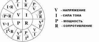
Electrical power (P) in physics is a measure that shows how quickly the transformation or transfer of electricity occurs. The unit of measurement is watt (W, W). The value of P depends on the voltage (U) and current (I) in the closed circuit.
For direct current, the load consumed by P is the result of the product of current and voltage:
P = I*U (A*B = W).
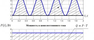
P in a constant current circuit
Attention! In this case, the values of both electrical characteristics are constant, which means that at every second of time their values are instantaneous.
The formula changes form if there is a source of electromotive force E (EMF) in the circuit:
P = I*E.
For circuits where the current changes its values periodically along a sinusoid, this formula is not suitable. It is necessary to calculate P based on its instantaneous values in the time interval.
The total power S in its value corresponds to the expression:
S = U*I,
Where:
- U – potential difference at the terminals, (V);
- I – current, (A).
To designate S, use the non-systemic unit B*A (V*A).
Loads included in variable current circuits can be:
- active;
- reactive: capacitive or inductive.
Active load (AH)
A similar load is the elements of devices that have active resistance. The working part of such devices heats up when electricity passes through them.
The current passing through the load does work, which is spent on heating and releasing thermal energy. How is this load measured? It is measured in ohms (ohms).
Examples of AN include: iron, electric stove, hair dryer coils, lamp filament, resistive resistance.
For your information. AN behaves the same way both with constant and with time-varying current.
Example AN
Capacitive load
Devices that can store energy in an electric field and create recirculation (full or partial return) of power are called capacitive loads. A capacitive load (EC) at an alternating voltage, passing current, shifts its phase forward by 900.
The main elements related to EN are:
- capacitors;
- cable lines (capacitance between cores);
- Power lines (power lines) of ultra-high voltage;
- generators operating in overexcitation mode.
EH delivers reactive power (Q).
Circuit with capacitor
Inductive load (IN)
A load in which the current is phase-shifted back from the voltage by 900 is called inductive. She also consumes Q.
Chain with coil
When an inductor (choke), which has a low active resistance, is connected to an alternating voltage network, an emf is formed in it. Electromotive force opposes applied voltage.
Important! In the case of pure inductance L, the resistance to sinusoidal current increases with increasing frequency. The average power P released by such a load is zero.
Examples of ID are:
- asynchronous motors;
- electromagnets;
- chokes;
- reactors;
- transformers;
- rectifiers
This also includes thyristor converters.
Physics of the process
When we are dealing with DC circuits, there is no need to talk about reactive power. In such circuits, the values of instantaneous and total power are the same. The exception is the moments of switching on and off capacitive and inductive loads.
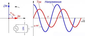
A similar situation occurs in the presence of purely active resistances in sinusoidal circuits. However, if devices with inductive or capacitive reactances are included in such an electrical circuit, a phase shift occurs in current and voltage (see Fig. 1).
In this case, a phase lag of the current is observed on inductances, and on capacitive elements the phase of the current shifts so that the current leads the voltage. Due to the violation of the current harmonics, the total power is decomposed into two components. Capacitive and inductive components are called reactive and useless. The second component consists of active capacities.
Rice. 1. Phase shift by inductive load
The phase shift angle is used when calculating the values of active and reactive capacitive or inductive powers. If the angle φ = 0, which occurs with resistive loads, then there is no reactive component.
Important to remember:
- the resistor consumes exclusively active power, which is released in the form of heat and light;
- inductors provoke the formation of a reactive component and return it in the form of magnetic fields;
- Capacitive elements (capacitors) cause the appearance of reactance.
Power triangle and cos φ
For clarity, let us depict the total power and its components in the form of vectors (see Fig. 2). Let us denote the total power vector by the symbol S, and assign the symbols P and Q to the vectors of the active and reactive components, respectively. Since the vector S is the sum of the current components, then, according to the rule of vector addition, a power triangle is formed.
Rice. 2. power factor
Applying the Pythagorean theorem, we calculate the modulus of the vector S:
From here you can find the reactive component:
Reactive component
We have already mentioned above that reactive power depends on the phase shift, and therefore on the angle of this shift. It is convenient to express this dependence in terms of cos φ. By definition, cos φ = P/S . This value is called the power factor and is designated Pf. Thus, Pf = cos φ = P/S.
Power factor, that is, cos φ, is a very important characteristic that allows you to evaluate the efficiency of current operation. This value is in the range from 0 to 1.
If the phase shift angle takes a zero value, then cos φ = 1, which means that P = S, that is, the total power consists only of active power, and there is no reactance. When the phases are shifted by an angle π/2, cos φ = 0, which means that only reactive currents dominate in the circuit (in practice, this situation does not arise).
From this we can conclude: the closer to 1 the coefficient Pf, the more efficiently the current is used. For example, for synchronous generators a coefficient of 0.75 to 0.85 is considered acceptable.
Reactive energy source
To understand the nature of the appearance of this energy and how to find reactive power, it is necessary to clarify that any electromagnetic or induction machine that operates on alternating current converts electricity into heat. For this transformation to occur, a magnetic field is needed. It, accordingly, is formed by watt-free energy. The reason is the absorption of energy from the induction circuit and its release back when the magnetic field decreases twice per power frequency cycle.
Nature of the phenomenon
Types of energy
Below are the main types of loads that are used in everyday life. They can be found in household appliances, as well as in various motors or sensors.
Active
For this work, Ohm's law is used, which is fulfilled every second of time and is similar to the rule for alternating current. This type is used in lamps for lighting or in electric stoves.
You might be interested in: How does electric current affect the human body?
Active capacitive load formula
Capacitive
This type converts the energy of electric current in an electric field over a certain period of time, and then converts it into electric current. And also, here the current strength will be ahead of the voltage.
An example would be a capacitor. Unfortunately, it is impossible to meet full reactive loads in any device. Each type does not have an efficiency of 100%, because there are energy losses in the air and so on. Therefore, the name active-reactive work is most often used.
Inductive
This type converts energy into a magnetic field, and then changes it into electric current. The current strength in this case will lag behind the voltage. For example, you can take an inductive coil or a throttle sensor on a car.
Functioning of rectifiers
Why is it needed?
Electricity transfers energy to a conductor to carry out a technical process. For the process to occur, the transferred force must be converted into heat and voltage. In this case, electricity must be supplied constantly, which is ensured by both types of power characteristics. The active one provides useful force, and the reactive one supports it in electric motor, transformer, furnace, welding, throttle and lighting installations.
Active load
Devices with active loads include heating devices (irons, electric stoves, incandescent lamps, electric kettles). Such devices produce heat and light. They do not contain inductance or capacitance. A resistive load converts electrical energy into light and heat.
A reactive load contains capacitance and inductance. These parameters have the quality of collecting energy and then sending it to the network. An example would be an electric motor, an electric meat grinder, a household tool (vacuum cleaner, food processor). That is, all devices that contain electric motors.
Power in an alternating current circuit
Electrical appliances connected to the electrical network operate in an alternating current circuit, so we will consider power under these conditions. However, first, let's give a general definition of the concept.
Power is a physical quantity that reflects the rate of conversion or transmission of electrical energy.
In a narrower sense, they say that electrical power is the ratio of the work performed over a certain period of time to this period of time.
If we rephrase this definition less scientifically, it turns out that power is a certain amount of energy that is consumed by the consumer over a certain period of time. The simplest example is an ordinary incandescent lamp. The rate at which a light bulb converts the electricity it consumes into heat and light is its power. Accordingly, the higher this indicator is initially for a light bulb, the more energy it will consume and the more light it will give off.
Since in this case there is not only a process of converting electricity into some other (light, heat, etc.), but also a process of oscillation of the electric and magnetic field, a phase shift appears between the current and voltage, and this should be taken into account in further calculations.
It will be interesting➡ What is static electricity and how to get rid of it. What causes static electricity?
When calculating power in an alternating current circuit, it is customary to distinguish active, reactive and apparent components.
Concept of active power
Active “useful” power is that part of the power that directly characterizes the process of converting electrical energy into some other energy. It is designated by the Latin letter P and measured in watts (W).
Calculated using the formula: P = U⋅I⋅cosφ,
where U and I are the root mean square value of the voltage and current of the circuit, respectively, cos φ is the cosine of the phase shift angle between voltage and current.
IMPORTANT! The formula described earlier is suitable for calculating circuits with a voltage of 220V, however, powerful units usually use a network with a voltage of 380V. In this case, the expression should be multiplied by the root of three or 1.73
Reactive power concept
Reactive “harmful” power is the power that is generated during the operation of electrical appliances with an inductive or capacitive load, and reflects the occurring electromagnetic oscillations. Simply put, this is energy that moves from the power source to the consumer, and then returns back to the network.
Naturally, this component cannot be used in business; moreover, it greatly harms the power supply network, which is why they usually try to compensate for it.
This value is denoted by the Latin letter Q.
REMEMBER! Reactive power is measured not in the usual watts (W), but in reactive volt-amperes (Var).
Calculated using the formula:
Q = U⋅I⋅sinφ,
where U and I are the rms value of the voltage and current of the circuit, respectively, sinφ is the sine of the phase shift angle between voltage and current.
IMPORTANT! When calculating, this value can be either positive or negative, depending on the phase movement.
The main difference between a reactive (capacitive and inductive) load is the presence, in fact, of capacitance and inductance, which tend to store energy and later release it into the network.
Power factor cosφ (read cosine phi) is a scalar physical quantity that reflects the efficiency of electrical energy consumption. Simply put, the cosφ coefficient shows the presence of a reactive part and the magnitude of the resulting active part relative to the total power.
The cosφ coefficient is found through the ratio of active electrical power to total electrical power.
NOTE! For a more accurate calculation, nonlinear distortions of the sinusoid should be taken into account, however, in conventional calculations they are neglected.
The value of this coefficient can vary from 0 to 1 (if the calculation is carried out as a percentage, then from 0% to 100%). From the calculation formula it is not difficult to understand that the greater its value, the greater the active component, which means the better the performance of the device.
An inductive load converts the energy of an electric current first into a magnetic field (during half a half cycle), and then converts the energy of the magnetic field into an electric current and transmits it to the network. Examples include asynchronous motors, rectifiers, transformers, and electromagnets.
IMPORTANT! When operating an inductive load, the current curve always lags the voltage curve by half a half cycle.
A capacitive load converts the energy of an electric current into an electric field, and then converts the energy of the resulting field back into an electric current. Both processes again occur for half a half cycle each. Examples are capacitors, batteries, synchronous motors.
IMPORTANT! During operation of a capacitive load, the current curve leads the voltage curve by half a half cycle.
Concept of total power. Capacity Triangle
Apparent power is a geometrically calculated value equal to the root of the sum of the squares of active and reactive powers, respectively. Denoted by the Latin letter S.
You can also calculate the total power by multiplying the voltage and current respectively.
S = U⋅I
IMPORTANT! Apparent power is measured in volt-amperes (VA).
The power triangle is a convenient representation of all the previously described calculations and relationships between active, reactive and apparent power.
The legs reflect the reactive and active components, the hypotenuse – the full power. According to the laws of geometry, the cosine of the angle φ is equal to the ratio of the active and total components, that is, it is the power factor.
Once again about power: active, reactive, apparent (P, Q, S), as well as power factor (PF)
From a client’s letter: Tell me, for God’s sake, why the power of the UPS is indicated in Volt-Amps, and not in the usual kilowatts. It's very stressful. After all, everyone has long been accustomed to kilowatts. And the power of all devices is mainly indicated in kW. Alexei. June 21, 2007
The technical characteristics of any UPS indicate the apparent power [kVA] and active power [kW] - they characterize the load capacity of the UPS. Example, see photos below:
The power of not all devices is indicated in W, for example:
- The power of transformers is indicated in VA: https://www.mstator.ru/products/sonstige/powertransf (TP transformers: see appendix) https://metz.by/download_files/catalog/transform/tsgl__tszgl__tszglf.pdf (TSGL transformers: see application)
- The power of capacitors is indicated in Var: https://www.elcod.spb.ru/catalog/k78-39.pdf (capacitors K78-39: see appendix) https://www.kvar.su/produkciya/25-nizkogo- napraygeniya-vbi (UK capacitors: see appendix)
- For examples of other loads, see the appendices below.
The power characteristics of the load can be accurately specified by one single parameter (active power in W) only for the case of direct current, since in a direct current circuit there is only one type of resistance - active resistance.
The power characteristics of the load for the case of alternating current cannot be accurately specified by one single parameter, since in the alternating current circuit there are two different types of resistance - active and reactive. Therefore, only two parameters: active power and reactive power accurately characterize the load.
The operating principles of active and reactive resistance are completely different. Active resistance - irreversibly converts electrical energy into other types of energy (thermal, light, etc.) - examples: incandescent lamp, electric heater (paragraph 39, Physics 11th grade V.A. Kasyanov M.: Bustard, 2007).
Reactance - alternately accumulates energy and then releases it back into the network - examples: capacitor, inductor (paragraph 40,41, Physics 11th grade V.A. Kasyanov M.: Bustard, 2007).
Further in any textbook on electrical engineering you can read that active power (dissipated by active resistance) is measured in watts, and reactive power (circulating through reactance) is measured in vars; Also, to characterize the load power, two more parameters are used: apparent power and power factor. All these 4 parameters:
- Active power: designation P , unit: Watt
- Reactive power: designation Q , unit: VAR (Volt Ampere reactive)
- Apparent power: designation S , unit: VA (Volt Ampere)
- Power factor: designation k or cosФ , unit of measurement: dimensionless quantity
These parameters are related by the relations: S*S=P*P+Q*Q, cosФ=k=P/S
CosФ also called power factor ( Power Factor - PF )
Therefore, in electrical engineering, any two of these parameters are specified to characterize power, since the rest can be found from these two.
For example, electric motors, lamps (discharge) - in those. data indicated P[kW] and cosФ: https://www.mez.by/dvigatel/air_table2.shtml (AIR engines: see appendix) https://www.mscom.ru/katalog.php?num=38 ( DRL lamps: see appendix) (for examples of technical data of different loads, see appendix below)
It's the same with power supplies. Their power (load capacity) is characterized by one parameter for DC power supplies - active power (W), and two parameters for sources. AC power supply. Typically these two parameters are apparent power (VA) and active power (W). See, for example, the parameters of the diesel generator set and the UPS.
Most office and household appliances are active (no or little reactance), so their power is indicated in Watts. In this case, when calculating the load, the UPS power value in Watts is used. If the load is computers with power supplies (PSUs) without input power factor correction (APFC), a laser printer, a refrigerator, an air conditioner, an electric motor (for example, a submersible pump or a motor as part of a machine tool), fluorescent ballast lamps, etc., all outputs are used in the calculation. . UPS data: kVA, kW, overload characteristics, etc.
See electrical engineering textbooks, for example:
1. Evdokimov F. E. Theoretical foundations of electrical engineering. - M.: Publishing House, 2004.
2. Nemtsov M.V. Electrical engineering and electronics. - M.: Publishing House, 2007.
3. Chastoedov L. A. Electrical engineering. - M.: Higher School, 1989.
Also see AC power, Power factor, Electrical resistance, Reactance https://en.wikipedia.org (translation: https://electron287.narod.ru/pages/page1.html)
Application
Example 1: the power of transformers and autotransformers is indicated in VA (Volt Amperes)
Power transformers with a rated output power of 25-60 VA https://www.mstator.ru/products/sonstige/powertransf (TP transformers)
https://metz.by/download_files/catalog/transform/tsgl__tszgl__tszglf.pdf (TSGL transformers)
| Single-phase autotransformers | |||
| TDGC2-0.5 kVa, 2A | AOSN-2-220-82 | ||
| TDGC2-1.0 kVa, 4A | Latr 1.25 | AOSN-4-220-82 | |
| TDGC2-2.0 kVa, 8A | Latr 2.5 | AOSN-8-220-82 | |
| TDGC2-3.0 kVa, 12A | |||
| TDGC2-4.0 kVa, 16A | |||
| TDGC2-5.0 kVa, 20A | AOSN-20-220 | ||
| TDGC2-7.0 kVa, 28A | |||
| TDGC2-10 kVa, 40A | AOMN-40-220 | ||
| TDGC2-15 kVa, 60A | |||
| TDGC2-20 kVa, 80A | |||
https://www.gstransformers.com/products/voltage-regulators.html (LATR / laboratory autotransformers TDGC2)
Example 2: the power of capacitors is indicated in VAR (Volt Amperes reactive)
https://www.elcod.spb.ru/catalog/k78-39.pdf (capacitors K78-39)
https://www.kvar.su/produkciya/25-nizkogo-napraygeniya-vbi (UK capacitors)
Example 3: technical data for electric motors contains active power (kW) and cosF
For loads such as electric motors, lamps (discharge), computer power supplies, combined loads, etc., the technical data indicates P [kW] and cosФ (active power and power factor) or S [kVA] and cosФ (apparent power and power factor) power).
https://www.mez.by/dvigatel/air_table2.shtml (AIR engines)
https://www.weiku.com/products/10359463/Stainless_Steel_cutting_machine.html (combined load – steel plasma cutting machine / Inverter Plasma cutter LGK160 (IGBT)
Technical data of discharge lamps contain active power (kW) and cosФ https://www.mscom.ru/katalog.php?num=38 (DRL lamps)
https://www.silverstonetek.com.tw/product.php?pid=365&area=en (PC power supply)
Appendix 1
If the load has a high power factor (0.8 ... 1.0), then its properties approach those of a resistive load. Such a load is ideal both for the network line and for power sources, because does not generate reactive currents and powers in the system.
If the load has a low power factor (less than 0.8 ... 1.0), then large reactive currents (and powers) circulate in the power line. This parasitic phenomenon leads to increased losses in the line wires (heating, etc.), disruption of the operating mode of sources (generators) and network transformers, as well as other problems.
Therefore, many countries have adopted standards regulating the power factor of equipment.
Addendum 2
Single-load equipment (for example, a PC power supply unit) and multi-component combined equipment (for example, an industrial milling machine containing several motors, a PC, lighting, etc.) have low power factors (less than 0.8) of internal units (for example, a PC power supply rectifier or an electric motor have power factor 0.6 .. 0.8). Therefore, nowadays most equipment has a power factor correction input unit. In this case, the input power factor is 0.9 ... 1.0, which corresponds to regulatory standards.
Appendix 3: Important Note Regarding UPS Power Factor and Voltage Stabilizers
The load capacity of the UPS and diesel generator set is normalized to a standard industrial load (power factor 0.8 with an inductive nature). For example, UPS 100 kVA / 80 kW. This means that the device can supply a resistive load with a maximum power of 80 kW, or a mixed (reactive-reactive) load with a maximum power of 100 kVA with an inductive power factor of 0.8.
With voltage stabilizers the situation is different. For the stabilizer, the load power factor is indifferent. For example, a 100 kVA voltage stabilizer. This means that the device can supply an active load with a maximum power of 100 kW, or any other (purely active, purely reactive, mixed) power of 100 kVA or 100 kVAr with any power factor of a capacitive or inductive nature. Please note that this is valid for a linear load (without higher current harmonics). With large harmonic distortions of the load current (high SOI), the output power of the stabilizer is reduced.
Addendum 4
Illustrative examples of pure active and pure reactive loads:
- A 100 W incandescent lamp is connected to an alternating current network of 220 VAC - everywhere in the circuit there is conduction current (through the wire conductors and the tungsten filament of the lamp). Load (lamp) characteristics: power S=P~=100 VA=100 W, PF=1 => all electrical power is active, which means it is completely absorbed in the lamp and converted into heat and light power.
- A 7 µF non-polar capacitor is connected to an alternating current network of 220 VAC - there is a conduction current in the wire circuit, and a bias current flows inside the capacitor (through the dielectric). Characteristics of the load (capacitor): power S=Q~=100 VA=100 VAr, PF=0 => all electrical power is reactive, which means it constantly circulates from the source to the load and back, again to the load, etc.
Addendum 5
To indicate the predominant reactance (inductive or capacitive), the power factor is assigned the sign:
+ (plus) – if the total reactance is inductive (example: PF=+0.5). The current phase lags behind the voltage phase by an angle Ф.
— (minus) – if the total reactance is capacitive (example: PF=-0.5). The current phase advances the voltage phase by angle F.
Appendix 6
In various fields of technology, power can be either useful or parasitic, REGARDLESS of whether it is active or reactive. For example, it is necessary to distinguish between the active useful power dissipated in the workload and the active parasitic power dissipated in the power line. So, for example, in electrical engineering, when calculating active and reactive powers, most often active power is the useful power transmitted to the load and is a real (not imaginary) quantity. And in electronics, when calculating capacitors or calculating transmission lines themselves, active power is parasitic power lost to heat up the capacitor (or line) and is an imaginary quantity. Moreover, division into imaginary and non-imaginary quantities is carried out only for the convenience of calculations. In fact, all physical quantities are of course real.
Additional questions
Question 1: Why do all electrical engineering textbooks, when calculating AC circuits, use imaginary numbers/quantities (for example, reactive power, reactance, etc.) that do not exist in reality?
Answer: Yes, all individual quantities in the surrounding world are real. Including temperature, reactance, etc. The use of imaginary (complex) numbers is only a mathematical technique that facilitates calculations. The result of the calculation is a necessarily real number. Example: reactive power of a load (capacitor) of 20 kVAr is a real energy flow, that is, real Watts circulating in the source-load circuit. But in order to distinguish these Watts from the Watts irretrievably absorbed by the load, they decided to call these “circulating Watts” reactive Volt Amperes [6].
Note: Previously, only single quantities were used in physics, and when calculating, all mathematical quantities corresponded to the real quantities of the surrounding world. For example, distance equals speed times time (S=v*t). Then, with the development of physics, that is, as more complex objects were studied (light, waves, alternating electric current, atom, space, etc.), such a large number of physical quantities appeared that it became impossible to calculate each one separately. This is not only a problem of manual calculation, but also a problem of compiling computer programs. To solve this problem, close single quantities began to be combined into more complex ones (including 2 or more single quantities), subject to transformation laws known in mathematics. This is how scalar (single) quantities (temperature, etc.), vector and complex dual quantities (impedance, etc.), triple vector quantities (magnetic field vector, etc.), and more complex quantities appeared - matrices and tensors (dielectric constant tensor, tensor Ricci and others). To simplify calculations in electrical engineering, the following imaginary (complex) dual quantities are used:
- Total resistance (impedance) Z=R+iX
- Apparent power S=P+iQ
- Dielectric constant e=e'+ie"
- Magnetic permeability m=m'+im"
- and etc.
Question 2:
The page https://en.wikipedia.org/wiki/Ac_power shows SPQ Ф on a complex, that is, imaginary/non-existent plane. What does all this have to do with reality?
Answer: It is difficult to carry out calculations with real sinusoids, therefore, to simplify the calculations, use a vector (complex) representation as in Fig. higher. But this does not mean that the SPQs shown in the figure are not related to reality. Real SPQ values can be presented in the usual form, based on measurements of sinusoidal signals with an oscilloscope. The values of SPQ Ф IU in the alternating current circuit “source-load” depend on the load. Below is an example [5] of real sinusoidal signals SPQ and Ф for the case of a load consisting of active and reactive (inductive) resistances connected in series.
Question 3: Using a conventional current clamp and a multimeter, a load current of 10 A and a load voltage of 225 V were measured. We multiply and get the load power in W: 10 A · 225V = 2250 W.
Answer: You have obtained (calculated) the total load power of 2250 VA. Therefore, your answer will only be valid if your load is purely resistive, then indeed Volt Ampere is equal to Watt. For all other types of loads (for example, an electric motor) - no. To measure all the characteristics of any arbitrary load, you must use a network analyzer, for example APPA137:
See further reading, for example:
[1]. Evdokimov F. E. Theoretical foundations of electrical engineering. - M.: Publishing House, 2004.
[2]. Nemtsov M.V. Electrical engineering and electronics. - M.: Publishing House, 2007.
[3]. Chastoedov L. A. Electrical engineering. - M.: Higher School, 1989.
[4]. AC power, Power factor, Electrical resistance, Reactance https://en.wikipedia.org (translation: https://electron287.narod.ru/pages/page1.html)
[5]. Theory and calculation of low power transformers Yu.N. Starodubtsev / RadioSoft Moscow 2005 / rev d25d5r4feb2013
[6]. International System of Units, SI, see e.g. GOST 8.417-2002. UNITS OF QUANTITIES
Engine reactive power accounting
Now let's see how the active energy is calculated for the same electric motors, on which the performance of a modern enterprise depends 70-80% - they turn pumps, machines, fans, conveyors, etc. and so on. If this is the case, then someone must constantly ensure that power consumption does not suddenly become unreasonably high. Of course, such control will most likely be carried out by a computer, but not without the participation of a person (engineer).
Most of all, the reactive energy of power is wasted in cases where the engine is idling, and if for pumps or conveyors this is an insignificant part, then for machine tools it is a very noticeable waste of the reactant. But, the threshold for the most efficient operation of electric motors is in the range of 60-100%, and at lower rates the useless energy consumption is increasingly approaching the idle value. What does this mean? The fact that when designing a workshop one should not overestimate its capacity - in practice this will only harm production.
Note: world practice shows that recently process engineers at leading enterprises are abandoning wound rotors and giving preference to asynchronous motors with a squirrel-cage rotor.
Concepts of active, apparent and reactive power
Let the electricity receiver be connected to a source of sinusoidal voltage u(t) = Usin(ωt) and consume a sinusoidal current i(t) = I sin (ωt -φ), shifted in phase relative to the voltage by an angle φ. U and I are effective values. The value of instantaneous power at the receiver terminals is determined by the expression
| p(t) = u(t) ?i(t) = 2UI sin(ωt) sin (ωt -φ) = UI cos φ - UI cos (2ωt -φ) | (5.1) |
and is the sum of two quantities, one of which is constant in time, and the other pulsates with double frequency.
The average value p(t) over the period T is called active power and is completely determined by the first term of equation (5.1):
Active power characterizes the energy consumed irreversibly by the source per unit time to produce useful work by the consumer. The active energy consumed by electrical receivers is converted into other types of energy: mechanical, thermal, compressed air and gas energy, etc.
The average value of the second term of instantaneous power (1.1) (pulsates with double frequency) over time T is equal to zero, i.e., its creation does not require any material costs and therefore it cannot perform useful work. However, its presence indicates that a reversible process of energy exchange occurs between the source and the receiver. This is possible if there are elements capable of accumulating and releasing electromagnetic energy - capacitance and inductance. This component characterizes reactive power.
The total power at the receiver terminals in complex form can be represented as follows:
| . | (5.2) |
The unit of measurement for apparent power is S = UI – VA.
Reactive power is a quantity that characterizes the loads created in electrical devices by fluctuations (exchange) of energy between the source and the receiver. For a sinusoidal current, it is equal to the product of the effective values of current I and voltage U and the sine of the phase angle between them: Q = UI sinφ. The unit of measurement is VAR.
Reactive power is not related to the useful operation of the electric motor and is spent only on the creation of alternating electromagnetic fields in electric motors, transformers, devices, lines, etc.
For reactive power, such concepts as generation, consumption, transmission, losses, balance are accepted. It is believed that if the current lags in phase with the voltage (inductive nature of the load), then reactive power is consumed and has a positive sign, and if the current leads the voltage (capacitive nature of the load), then reactive power is generated and has a negative sign.
The main consumers of reactive power at industrial enterprises are asynchronous motors (60–65% of total consumption), transformers (20–25%), valve converters, reactors, overhead electrical networks and other receivers (10%).
The transfer of reactive power loads electrical networks and the equipment installed in them, reducing their capacity. Reactive power is generated by synchronous generators of power plants, synchronous compensators, synchronous motors (excitation current regulation), capacitor banks (BC) and power lines.
The reactive power generated by the network capacity has the following order of magnitude: a 20 kV overhead line generates 1 kVAr per 1 km of a three-phase line; underground cable 20 kV – 20 kVAr/km; overhead line 220 kV – 150 kVAr/km; underground cable 220 kV – 3 MVAr/km.
Power factor and reactive power factor.
The vector representation of quantities characterizing the state of the network leads to the representation of reactive power Q by a vector perpendicular to the active power vector P (Fig. 5.2). Their vector sum gives the total power S.
Rice. 5.1. Capacity Triangle
According to Fig. 5.1 and (5.2) it follows that S2 = P2 + Q2; tgφ = Q/P; cosφ = P/S.
The main standard indicator characterizing reactive power was previously the power factor cosφ. At the inputs supplying an industrial enterprise, the weighted average value of this coefficient should have been in the range of 0.92–0.95. However, choosing the P/S ratio as a normative one does not give a clear idea of the dynamics of changes in the real value of reactive power. For example, when the power factor changes from 0.95 to 0.94, the reactive power changes by 10%, and when the same factor changes from 0.99 to 0.98, the increase in reactive power is already 42%. When making calculations, it is more convenient to operate with the ratio tgφ = Q/P, which is called the reactive power factor.
Enterprises with a connected power of more than 150 kW (with the exception of “domestic” consumers) have determined the limit values of the reactive power factor consumed during hours of high daily load of the electrical network - from 7 to 23 hours (Order of the Ministry of Industry and Energy of the Russian Federation dated February 22, 2007 No. 49 “On the procedure for calculating the ratio of active and reactive power consumption for individual power receiving devices of electrical energy consumers, used to determine the obligations of the parties in contracts for the provision of services for the transmission of electrical energy”).
Limit values of reactive power factors (tgφ) are standardized depending on the position of the point (voltage) of connection of the consumer to the network. For a network voltage of 100 kV tgφ = 0.5; for networks 35, 20, 6 kV – tgφ = 0.4 and for networks 0.4 kV – tgφ = 0.35.
The introduction of new policy documents on reactive power compensation was aimed at increasing the efficiency of the entire power supply system from power system generators to power receivers.
With the introduction of the reactive power factor, it became possible to represent active power losses through active or reactive power: P = (P2/U2) R (l + tg2φ).
The angle between the power vectors P and S corresponds to the angle φ between the vectors of the active component of the current Ia and the total current I, which, in turn, is the vector sum of the active current Ia, which is in phase with the voltage, and the reactive current Iр, which is at an angle of 90 ° to him. This arrangement of currents is a calculation technique associated with the decomposition into active and reactive power, which can be considered natural.
Most consumers require reactive power because they operate due to changes in the magnetic field. For the most commonly used engines in normal operation, the following approximate values of tgφ can be given.
| Electric motors | tgφ | cosφ |
| Single phase asynchronous motor | 1,30–0,90 | 0,61–0,74 |
| Three-phase asynchronous motor | 1,00–0,50 | 0,70–0,89 |
| Brushed motor | 1,30–1,00 | 0,61–0,70 |
At the moment of starting the engines, a significant amount of reactive power is required, with tgφ = 4–5 (cosφ = 0.2–0.24).
Synchronous machines have the ability to consume or produce reactive power depending on the degree of excitation.
In synchronous generators and motors, the size of the excitation circuits limits the possibility of supplying reactive power to maximum values of tgφ = 0.75 (cosφ = 0.8) or up to tgφ = 0.5 (cosφ = 0.9) (Table 5.1).
Synchronous motors produced by the domestic industry are designed for a leading power factor (cosφ = 0.9) and with a rated active load Pnom and voltage Unom can generate rated reactive power Qnom ≈ 0.5 Pnom.
If the SD is underloaded in terms of active power β = P/Pnom < 1, overload in terms of reactive power α = Q/Qnom > 1 is possible.
The advantage of SD used for reactive power compensation compared to KB is the ability to smoothly regulate the generated reactive power. The disadvantage is that the active losses for generating reactive power for SD are greater than for KB.
Additional active losses in the LED winding caused by the generated reactive power within the range of cosφ variation from 1 to 0.9 at the rated active power of the LED equal to Pnom, kW:
Pnom = Q2nomR /U2nom,
where Qnom is the rated reactive power of the SD, kV Ar; R – resistance of one phase of the LED winding in a heated state, Ohm; Unom – rated network voltage, kV.
In power supply systems of industrial enterprises, CBs compensate for the reactive power of the base (main) part of the load schedules, and SDs reduce the load peaks of the schedule.
Table 5.1
Dependences of the overload factor for reactive power of synchronous motors
| Series, rated voltage, engine speed | Relative voltage at motor terminals U/Unom | Reactive power overload factor α at load factor β | ||
| 0,90 | 0,80 | 0,70 | ||
| SDN, 6 and 10 kV (for all rotation speeds) SDN, 6 kV: 600–1000 rpm 370–500 rpm 187–300 rpm 100–167 rpm SDN, 10 kV: 1000 rpm 250–750 rpm STD, 6 and 10 kV, 3000 rpm SD and SDZ, 380 V (for all rotation speeds) | 0,95 1,00 1,05 1,10 1,10 1,10 1,10 1,10 1,10 0,95 1,00 1,05 1,10 0,95 1,00 1,05 1,10 | 1,31 1,21 1,06 0,89 0,88 0,86 0,81 0,90 0,86 1,30 1,32 1,12 0,90 1,16 1,15 1,10 0,90 | 1,39 1,27 1,12 0,94 0,92 0,88 0,85 0,98 0,90 1,42 1,34 1,23 1,08 1,26 1,24 1,18 1,06 | 1,45 1,33 1,17 0,96 0,94 0,90 0,87 1,00 0,92 1,52 1,43 1,31 1,16 1,36 1,32 1,25 1,15 |
Synchronous compensators.
A type of SD is synchronous compensators (SC), which are SD without load on the shaft. Currently, SCs with a capacity above 5000 kV?Ar are produced. They have limited use in industrial networks. To improve the voltage quality indicators of powerful electric generators with sharply variable, shock loads (arc furnaces, rolling mills, etc.), SCs are used.
Static thyristor compensating devices.
In networks with sharply variable shock loads at a voltage of 6–10 kV, it is recommended to use not capacitor banks, but special high-speed reactive power sources (RPS), which should be installed near such electric power plants. The IRM diagram is shown in Fig. 5.2. It uses inductances LR and unregulated capacitances C1–C3 as an adjustable inductance.
Rice. 5.2. Fast acting reactive power sources
Inductance regulation is carried out by thyristor groups VS, the control electrodes of which are connected to the control circuit. The advantages of static IRM are the absence of rotating parts, the relative smoothness of regulation of reactive power supplied to the network, the possibility of three- and four-fold overload of reactive power. The disadvantages include the appearance of higher harmonics, which can arise during deep regulation of reactive power.
Due to additional power losses in the network caused by the consumption of reactive power, the total electricity consumption increases. Therefore, reducing reactive power flows is one of the main tasks of operating electrical networks.
Occurrence of reactive power
Let's say the circuit contains a DC power supply and an ideal inductance. Turning on the circuit generates a transient process. The voltage tends to reach the nominal value; the growth is actively hampered by the inductance’s own flux linkage. Each turn of the wire is bent in a circular path. The resulting magnetic field will cross the adjacent segment. If the turns are located one after the other, the nature of the interaction will increase. This is called intrinsic flux linkage.
It will be interesting➡ Vector diagram of currents and voltages
The nature of the process is as follows: the induced EMF prevents changes in the field. The current tries to grow rapidly, the flux linkage pulls back. Instead of a step we see a smoothed protrusion. The energy of the magnetic field is spent to interfere with the process that created it. The case of reactive power occurrence. The phase differs from the beneficial one and is harmful. Ideal: the direction of the vector is perpendicular to the active component. It is assumed that the wire resistance is zero (a fantastic scenario).
When the circuit is turned off, the process will be repeated in reverse order. The current tends to instantly drop to zero; energy is stored in the magnetic field. If the inductance disappears, the transition will take place suddenly, flux linkage gives the process a different coloring:
- A decrease in current causes a decrease in the magnetic field strength.
- The effect produced induces the back-EMF of the turns.
- As a result, after the power source is turned off, the current continues to exist, gradually attenuating.
Graphs of voltage, current, power
Reactive power is a certain link of inertia, constantly lagging and interfering. The first question is: why then are inductors needed? Oh, they have plenty of useful qualities. Benefit makes you put up with reactive power. A common positive effect is the operation of electric motors. Energy transfer occurs through magnetic flux. Between the turns of one coil, as shown above. A permanent magnet, a choke, and everything capable of being captured by an induction vector are subject to interaction.
The cases cannot be called comprehensive in a descriptive sense. Sometimes clutch flow is used in the form shown as an example. The principle is used by ballasts of gas-discharge lamps. The inductor is equipped with a myriad of turns: turning off the voltage does not cause a smooth decrease in current, but a surge of large amplitude of the opposite polarity. The inductance is great: the response is truly amazing. Exceeds the original 230 volts by an order of magnitude. It is enough for a spark to appear and the light bulb to light up.
Reactive power and capacitors
Reactive power is stored by magnetic field energy by inductances. What about the capacitor? Acts as a source of the reactive component. Let us supplement the review with the theory of vector addition. The average reader will understand. Oscillatory processes are often used in the physics of electrical networks. The well-known 220 volts (now accepted 230) in a 50 Hz outlet. A sine wave whose amplitude is 315 volts. When analyzing circuits, it is convenient to represent them as a clockwise rotating vector.
Graphical circuit analysis
The calculation is simplified and the engineering representation of reactive power can be clarified. The current phase angle is considered equal to zero and is plotted to the right along the abscissa axis (see figure). The reactive energy of the inductance is in phase with the UL voltage and is 90 degrees ahead of the current. Ideal case. Practitioners have to take into account the winding resistance. Part of the power will be reactive in inductance (see figure). The angle between projections is important. The value is called power factor. What does this mean in practice? Before answering the question, let's consider the concept of a resistance triangle.
Practical interpretation of power factor
Many people notice a discrepancy in the case of practical consideration of reactive power. To reduce the coefficient, it is recommended to include large capacitors in parallel with the motor windings. The inductive reactance balances the capacitive reactance, the current is again in phase with the voltage. It's difficult to understand for this reason:
- Let's say the primary winding of a transformer is connected to an alternating voltage source.
- Ideally, active resistance is zero. Power must be reactive. But this is bad: they tend to make the angle between voltage and current zero!
Power factor
The amount of energy stored by the field is determined by the size of the inductance or capacitance. You can read it in any physics textbook for universities (Physics Course by Zhdanov and Maranjyan, vol. 2, p. 234), more precisely, it is proportional to the square of the quantity. The theory of reactive power assumes: a certain energy is stored each period by parasitic inductance, capacitance, and then goes into the external circuit. This results in a kind of circulation inside the oscillatory circuit. The connecting wires become very hot if the inductance is too far from the capacitance.
But! The oscillatory process is indifferent to the operation of motors and transformers. The theory of reactive power assumes that all energy oscillates. To the last drop. In a transformer or motor, an active “leakage” of energy occurs from the field to perform work and induce current in the secondary winding. Energy cannot circulate between source and consumer.
In a real chain, the process of coordinating individual sections makes it difficult. To be on the safe side, suppliers require that capacitors be installed in parallel with the motor winding so that the energy circulates in the local segment and does not escape outside, heating the connecting wires. It is important to avoid overcompensation. If the capacitors are too large, the battery will cause the power factor to increase.
As for the phase shift, it occurs on the secondary winding of the substation transformer. That's not the role. The engine is running, some of the energy is not converted into useful work and is reflected back. The result is a power factor. The participating component of inductance is a technological, structural defect. The part that is not useful. We will compensate by adding capacitor blocks.
The correct matching is checked based on the fact that there is no phase shift between the voltage and current of a running electric motor. Excess energy circulates between the excess inductance of the windings and the installed capacitor unit. The goal of the event was achieved - to avoid heating the conductors of the network supplying the device.
It will be interesting➡ The phenomenon of self-induction
Nonlinear load
It has the peculiarity that voltage and current are not proportional. Nonlinear loads include televisions, stereos, electronic desktop clocks, computers and its components. The nonlinearity itself is due to the fact that this electronic device uses switching power supplies. To recharge the capacitors in the switching power supply, the top of a sine wave is sufficient.
The rest of the time, the capacitor does not consume energy from the network. In this case, the current has a pulse quality. What does this all lead to? This causes the sine wave to become distorted. But not all electronic devices work with a distorted sine wave. This problem is solved through the use of double conversion stabilizers, where mains power is converted to constant power. Then it is converted from a constant into a variable of the desired shape and amplitude.
Reactive electricity concept
This type of electricity is inherent in circuits that contain reactive elements. Reactive electricity is the portion of the total incoming power that is not spent on useful work.
In DC circuits there is no concept of reactive power. In AC circuits, a reactive component occurs only when an inductive or capacitive load is present. In this case, there is a mismatch between the phase of the current and the phase of the voltage. This phase shift between voltage and current is indicated by the symbol “φ”.
With an inductive load in the circuit, a phase lag is observed, and with a capacitive load, it is advanced. Therefore, only part of the total power reaches the consumer, and the main losses occur due to useless heating of devices and instruments during operation.
Power losses occur due to the presence of inductive coils and capacitors in electrical devices. Because of them, electricity accumulates in the circuit for some time. After this, the stored energy is fed back into the circuit. Devices whose power consumption includes a reactive component of electricity include portable power tools, electric motors and various household appliances. This value is calculated taking into account a special power factor, which is designated as cos φ.
Reactive power - once again briefly about the main thing
Increasingly, in various publications and the media, as part of information on the implementation of the Federal Law of November 23, 2009 N 261-FZ “On energy saving and increasing energy efficiency...” information is found on the fight against reactive power in network companies and industrial enterprises. What kind of evil is this that network companies are spending hundreds of millions of rubles to combat it, developing special long-term targeted programs for managing reactive power in electrical networks, and campaigning among large electricity consumers to install reactive power compensation devices? Is it so important and is this compensation necessary?
Often, many consumers subconsciously believe that generating companies supply two types of electrical energy, since they pay bills for consumed active and reactive power, which make up the total power supplied by generating substations. Although in fact the concept of reactive power, although generally accepted and used, is not entirely correct, since physically reactive power (namely in the classical understanding of power, as the ratio of work to time) does not exist, since it does not do any work.
Active power is that part of electrical energy that is used to perform useful work and, during consumption, is converted into other types of energy, such as thermal, mechanical or light.
The name reactive power, by analogy with reactance, is due to the ability of inductive and capacitive elements to accumulate and release stored magnetic or electrical energy back into the network, and exhibit apparent resistance only in alternating current circuits . While active resistance depends only on the specific conductor material.
According to the generally accepted statement, the conventional term “reactive power” is understood as the second component of total power in AC networks, characterizing the intensity of exchange/circulation of electrical energy between the source and the reactive load connected to it (inductor elements and/or capacitors), which is necessary only for calculations determining the influence of reactive elements on the network.
Inductive (coils in transformers, chokes, induction furnaces, motors, etc.) and capacitive (capacitor banks) elements practically do not consume electricity (excluding magnetic dispersion and leakage in capacitors), although it is used to create electromagnetic and electric/electrostatic fields , but during the discharge process it returns back to the network. Since energy circulates, there are correspondingly changes in current and voltage, which can be calculated in the form of conditional reactive power used only to carry out these transformations.
For electrical circuits, depending on the equipment connected, three situations can be distinguished:
- if the equipment has an almost pure active (resistive) load, for example, incandescent lamps, irons, electric stoves and other devices, then the alternating current flowing through the circuit will be in phase with the voltage (see figure below). Those. current and voltage will be in phase, the angle between voltage and current ϕ=0. For this case, power is completely active and is defined as the product of current and voltage. The power transmitted by the source is completely spent on doing work.
Rice. Diagram of voltage, current and power for a resistive (resistive) load.
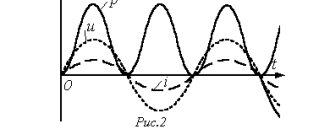
- Only inductive loads predominate in the equipment. In this case, there is a situation when the current lags behind the voltage by an angle ϕ (see figure below), this is due to the inherent inertia of inductance, which delays the appearance of current. For the ideal case, when ϕ = 90° (somewhat suitable for asynchronous motors and transformers operating at no-load ϕ > 80°), as can be seen from the figure, in the first quarter of the period energy is consumed to create a magnetic field, and in the second a quarter of it is generated back into the network, i.e. power exchange occurs.
Rice. Diagram of voltage, current and power for an inductive load.
- the third situation is similar to the previous one, but in this case, for equipment with only a capacitive load, the current passing through it will lead the voltage (see figure below).
Rice. Diagram of voltage, current and power for a capacitive load.
In reality, the load has a more or less pronounced inductive-capacitive load (see figure below), depending on the parameters of the equipment itself. Due to the phase shift of voltage and current, the amount of active power used to perform useful work in systems with an inductive load decreases, since part of the electrical energy (reactive power) will circulate in the power system and will be spent only on creating magnetic fields, without doing anything useful, which in turn leads to an increase in the current required for full operation of the equipment. At the same time, as is known, all conductors have active resistance, and the circulation of large currents in the system will lead to their heating (the amount of heating, and, accordingly, losses, as is known, is proportional to the square of the current), and, accordingly, to losses of electrical energy.
Rice. Diagram of voltage, current and power for an inductive-capacitive load.
To calculate the total power, the formula is used,
where P is active power, determined by the formula,
Q is reactive power, determined by the formula,
U is voltage, I is current, ϕ is the angle between voltage and current.
As mentioned above, reactive power flows in the network do not perform useful work; they load the source, power lines, and all switching equipment installed between generating stations and end consumers, as well as heating cables and high-voltage transmission lines, thereby reducing their capacity ability (as the temperature increases, the resistance of the wires increases) and creating useless heat. Why warm the environment and still pay money for it?
In addition, a decrease in throughput and an increase in losses due to heating of wires leads to significant voltage deviations, standardized in accordance with GOST 13109-97, which ultimately negatively affects:
- a decrease in torque and rotation speed of asynchronous motors, which ultimately, with an appropriate load, can lead to its stop. Simultaneously with a decrease in voltage (a decrease in reactive power by 2-3% for each percent of voltage), the motor current will proportionally increase, which can lead to overheating of the winding insulation and a decrease in its service life.
- a decrease in the luminous output of lighting fixtures, which will affect the productivity of workers. For fluorescent lamps, a decrease/increase in voltage by 10% leads to a reduction in their service life by 20-25%. In addition, given that many manufacturers of compact fluorescent lamps do not use power factor correctors (PFC) in electronic ballasts, an increase in the supply voltage leads to an increase in reactive power consumption. Without CFC, the power factor value is at the level of 0.5, which makes the compensation problem also relevant for individual electricity consumers with a significant number of these lamps.
- quality of work and duration of operation of various household electrical equipment.
- on the quality of operation of welding equipment, so with voltage deviations of up to 15%, spot welding machines will be guaranteed to be defective.
- quality and stability of the operation of energy systems, a situation such as a “voltage avalanche” may arise due to the growing shortage of reactive power.
Based on the foregoing, solving problems of reactive power compensation occupy one of the most important places among measures aimed at increasing the efficiency of distribution, transmission and consumption of electricity. After all, high-quality power supply depends on their results, as well as savings on payments for consumed electricity (active and reactive) and material resources. Therefore, depending on the specific situation, all issues regarding reactive power compensation must be resolved taking into account modern developments and solutions for this area.
The main dimensionless quantity characterizing the predominance of the reactive component in the equipment is the power factor, which is numerically equal to the cosine of the current shift relative to the voltage applied to the load or the ratio of the active power consumed by the equipment (P) to the total (S).
Thus, many enterprises and generating/distribution network companies strive to increase cos(ϕ) to 1 in order to significantly reduce the amount of reactive power consumed. As mentioned above, in everyday life and industry, equipment with an inductive nature of the load mainly predominates, with the current lagging behind the voltage, therefore, using devices with a capacitive load, it is possible to reduce the shift between current and voltage in phase, and accordingly achieve cos(ϕ) close to one.
This can be achieved at minimal cost by using compensating units built on the basis of capacitors (capacitor units KRM, AUKRM, banks of static capacitors), more expensive synchronous motors in overexcitation mode or thyristor circuits with filters installed directly near equipment with a predominant reactive load or groups, at distribution substations of the enterprise. Thus, the creation of electrical energy with a predominant capacitive characteristic from substations generating synchronous generators is generally not advisable, due to the same losses during the transmission and distribution of electrical energy.
Recently, capacitor units AUKRM have become increasingly in demand, allowing for more accurate correction of the power factor, taking into account changes in values, power consumption from load currents, voltage, and time of day.
At the same time, when forming a capacitor installation, it is desirable to ensure the smallest possible control step, but using a minimum number of capacitors. Ultimately, the competent choice of specific equipment for reactive power compensation is determined on the basis of technical and economic calculations, the nature of the reactive load prevailing in the enterprise's networks, which will allow achieving a positive economic effect with minimal payback periods for the installed equipment.
Based on materials
Reactive power calculation
The power factor ranges from 0.5 to 0.9; The exact value of this parameter can be found in the electrical device data sheet. The apparent power must be determined as the active power divided by the factor.
For example, if the passport of an electric drill indicates a power of 600 W and a value of 0.6, then the total power consumed by the device will be equal to 600/06, that is, 1000 VA. In the absence of passports for calculating the total power of the device, the coefficient can be taken equal to 0.7.
Since one of the main tasks of existing power supply systems is to deliver useful power to the end user, reactive power losses are considered a negative factor, and an increase in this indicator calls into question the efficiency of the electrical circuit as a whole. The balance of active and reactive power in a circuit can be visualized in the form of this funny picture:
Power measurement
Active power in networks is measured using a wattmeter
Digital wattmeter Analog wattmeter
Depending on the load connection diagram and its nature (symmetrical or asymmetrical), the connection diagrams of the devices may vary. Consider the case with a symmetrical load:
Scheme for connecting a wattmeter with a symmetrical load
Here the measurement is carried out in only one phase and then multiplied by three according to the formula. This method allows you to save on instruments and reduce the dimensions of the measuring setup. It is used when greater measurement accuracy in each phase is not needed.
Measurement with unbalanced load:
Scheme for connecting a wattmeter with an asymmetric load
This method is more accurate, since it allows you to measure the power of each phase, but it requires three instruments, large overall dimensions of the installation and processing of readings from three instruments.
Measuring in a circuit without a neutral conductor:
Scheme for connecting a wattmeter in the absence of a neutral wire
This circuit requires two devices. This method is based on Kirchhoff's first law
IA+IB+IC=0. It follows from this that the sum of the readings of two wattmeters is equal to the three-phase power of this circuit. The vector diagram for this case is shown below:
Vector diagram for switching on two wattmeters for different types of load
We can conclude that instrument readings depend not only on the magnitude, but also on the nature of the load.
From the diagram it follows that we can determine the instrument readings analytically:
Having analyzed the obtained result, we can conclude that, with a predominance of active load (φ=0), the measurement results of wattmeters are identical (W1=W2). With active and inductive (RL), the readings of W1 are less than W2 (W12); with φ>600, the readings of W1 are generally negative (W1<0).
With active and capacitive (RC) and W1>W2, and with φ<-600 readings W2 <0.
With the modern development of technology, digital wattmeters have appeared. Unlike analog ones, they are smaller in size, much lighter and less bulky. Moreover, digital wattmeters can record current, voltage, measure cosφ in the network, and more. They allow you to monitor various quantities in real time and issue warnings when they deviate. This is very convenient and there is no need to measure current, voltage, and then calculate it all mathematically. The digital wattmeter is enclosed in a housing and is connected (for household consumers) in the most usual way - like a regular consumer - by plugging a plug into a socket.
Differences
The difference between the values is that the active power characteristic shows the efficiency of the devices, and the reactive one is the transfer of this efficiency. The difference is also observed in definition, symbol, formula and significance.
You might be interested in Features of kW and kVA units of measurement
Note! As for the meaning, the second is needed only to control the voltage created from the first value and overcome power fluctuations.
The meaning of reactive load
Any reactive load creates a time shift between the phases of current and voltage. This value is measured in degrees. The most visual is the vector representation of electrical parameters. If you connect an inductance, the voltage will lead the current. The angle between them is denoted in formulas by the letter “ϕ” (“Phi” in Greek).
Time and vector diagrams show how the main parameters change when connecting inductive (capacitive) elements
The picture shows that when a capacitive load is connected, the vectors “swap” places. Under ideal conditions, the shift between vectors is 90°. In reality, one should take into account the influence of electrical resistance of the circuit and imperfect designs. Taking into account the characteristics of the elements, it should be recalled that in the inductance (capacitance), while maintaining the parameters of the power source, the current (voltage) changes smoothly, respectively.
Why is the voltage in the network variable?
To explain the present situation, we need to make a brief excursion into history. Electricity has been known to man for hundreds (according to some sources, thousands of years). However, the truly massive use of this energy began relatively recently - at the end of the 19th century. It was then (1879) that Edison patented the first functional device that helped solve lighting problems. To power light bulbs, he began installing DC networks.
Ten years later, Tesla created alternating current generators. After fierce competition, it was his method of transmitting energy over distances that won. This result was achieved more by market methods than by careful comparison of consumer characteristics.
Calculation of power by current and voltage
Electric current power formula
You can calculate consumption P by knowing these two parameters I and U of the network. Before choosing cables or wires for wiring in an apartment, you need to decide on the P consumers that can be connected to them. The calculation is made after the measuring instruments record the current readings of the current strength I (A), as well as the voltage U (V).
Single-phase 220 volt network
When connecting an active load to the circuit, use the formula: P = U*I. If there is a phase shift between U and I, use the formula: P = U*I* cosφ.
Three-phase network voltage 380 V
In a three-phase AC network with a phase shift, the result of the last formula is multiplied by √3. The value of the angle cosφ can be clarified in the reference book.
Cosφ table for household devices
When choosing a wire cross-section, the total power of future consumers and the network voltage are usually known.
All you need is the current strength, the formula through power and voltage is:
I = P / (U *cosφ).
The formula for calculating current using power and voltage has the following components:
- P – known power of the device, (W);
- U – supply voltage, (220/380 V);
- cosφ – phase shift angle.
Current calculation can be done using an online calculator.
Online calculator – general view of the interface