Electrical power, designated in the diagrams by the letter P, is a physical quantity that characterizes the rate of conversion or transmission of electricity. The standard concept is the effort to move an electric charge along a route from point F1 to point F2.
The electrical power of a device is a key parameter that determines the potential for its operation in the electrical network. Used to calculate circuits and operating modes of equipment to ensure the safety of electrical networks. The greater the power of the device, the faster they perform the desired action.
Formulas for calculating voltage, current, power, resistance Source amperof.ru
Electrical current through voltage and current
Since the potential difference calculated by the formula (F1-F2) determines the voltage (U), it is easy to conclude that the relationship established by Ohm’s law cannot be used. Electrical power (P) is also qualified by the current strength (I) on a specific section of the line. Final expression: P = U x I.
What is the load determined in terms of current and resistance?
Through a simple conversion, the electrical energy consumption is determined using the following formula: P = I2 x R. This shows the dependence of the power on the nominal value of the resistor connected to the line of the network element. For a complete circuit, the source resistance (internal) and the conductance of the connection point are indicated.
How to calculate power knowing current and voltage
The power characteristics of electrical installations are calculated using the formula:
We recommend reading: Transistors and diodes: how semiconductors work
P=U*I - direct current;
P=U*I*cos(phi) – alternating current of a single-phase network.
P=1.73*U*I*cos(phi) - three-phase network.
The article provides simplified formulas for calculating the active power of the electrical network, which give approximate results.
To obtain accurate results, it is also necessary to take into account reactance and ordinary resistance, as well as losses.
What is it and how to calculate the load
Electric current load is a quantity characterizing its properties. Shows how much energy is consumed by electrical appliances. The current power is measured using a special device - a wattmeter.
If you connect a meter in series, you can check the current strength. When connecting in parallel, the voltage is determined. The amount of circuit consumption is calculated using the formulas: P = I x U or P = U2/ R = I2 x R.
The electrical load is equal to the voltage across the consumer multiplied by the amount of current flowing through it.
P = U x I
The formula indicates which measurements determine this parameter. If the load is active, it is measured in Watts, the reactive unit of electrical power is VA.
Reactive unit of electrical power - VA Source infourok.ru
All power formulas
Knowing the definitions, it is not difficult to understand the power formulas used in different branches of physics - in mechanics and electrical engineering.
In mechanics
Mechanical power (N) is equal to the ratio of work to the time in which it was performed.
Basic formula:
N = A / t, where A is the work, t is the time it takes to complete it.
If we remember that work is the product of the modulus of force, the modulus of displacement and the cosine of the angle between them, we obtain a formula for measuring work.
If the directions of the modulus of application of force and the modulus of displacement of the object coincide, the angle will be equal to 0 degrees, and its cosine will be equal to 1. In this case, the formula can be simplified:
A=F×S
We use this formula to calculate power:
N = A / t = F × S / t = F × V
In the last expression, we assume that the speed (V) is equal to the ratio of the movement of the object to the time during which this movement occurred.
In electrical engineering
In general, electrical power (P) refers to the rate at which energy is transferred. It is equal to the product of the voltage in a section of the circuit by the amount of current passing through this section.
P = I × U , where I is voltage, U is current.
In electrical engineering there are several types of power: active, reactive, total, peak, etc. But this is a topic for a separate material, now we will practice solving problems based on a general understanding of this quantity. Let's see how to find power using the above physics formulas.
Problem 1
Let's say a person lifts a bucket of water from a well, applying a force of 60 N. The depth of the well is 10 m, and the time required for lifting is 30 seconds. What will be the human power in this case?
Solution:
Let us first find the amount of work using the fact that we know the distance of movement (the depth of the well is 10 m) and the applied force is 60 N.
A = F × S = 60 N × 10 m = 600 J
When the value of work and time is known, finding the power is easy:
N = A / t = 600 J / 30 sec = 20 W
Answer: the power of a person when lifting a bucket is 20 watts.
Problem 2
A 100 W lamp is turned on in the room. The home power supply voltage is 220 V. How much current passes through this lamp?
Solution:
We know that P = 100 W and U = 220 V.
Since P = I × U, therefore I = P / U.
I = 100 / 220 = 0.45 A.
Answer: A current of 0.45 A will pass through the lamp.
How to determine the maximum current load
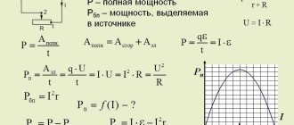
The useful power shows the maximum value in a situation where the load resistance R is compared with the same parameter inside the source - r.
R = r.
P max = E2 / 4r, where E is the driving force of the current source.
To calculate the maximum current load for an electrical device, you need to know the rated load parameter and the AC input voltage. The technical data sheet of the device, manual or emblem contains the first indicator.
For example, when the appliance rating (P) is 12 W, the maximum current consumption at AC voltage will be for:
- 120 V – I = 12/120 = 0.100 A or 100 mA.
- 220 V – I = 12 / 220 = 0.055A or 55 mA.
If necessary, the amount of electricity consumed is expressed through a complex value. For this purpose, basic relationships are used, impedance is used instead of resistance.
Formulas for calculating power for single-phase and three-phase power circuits
In the ideal theoretical case, a three-phase circuit consists of three identical single-phase circuits. In practice there are always some deviations. But, in most cases, they are neglected in analyzes.
Therefore, we consider the simplest question first.
Graphs and formulas for single-phase voltage
How does a resistor work?
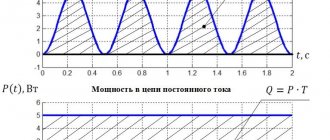
On a purely resistive resistance, the sinusoids of current and voltage coincide in angle and are directed equally at each half-cycle. Therefore, their product, which expresses power, is always positive.
Its value at an arbitrary moment of time t is called instantaneous, denoted by the lowercase letter p.
The average power value over one period is called the active component. Its graph for alternating current has the shape of a symmetrical burst with a maximum value of Pm in the middle of each half-cycle T/2.
If we take half of its value Pm/2 and draw a straight line during one period T, we will get a rectangle with ordinate P.
Its area is equal to two areas of the graphs of the active components of any one half-cycle. If you look at the picture more closely, you can imagine that the top part of the splash has been cut off, turned upside down and filled the free space below.
Presentation of this graph helps to remember that the power of direct and alternating current at active resistance is calculated using the same formula and does not change its sign.
The graph of instantaneous values of active power of alternating current on a resistive resistance has the form of repeating positive waves. But in one period it does the same work as in direct current and voltage circuits.
There is no reactive loss created across the resistor.
How inductance works
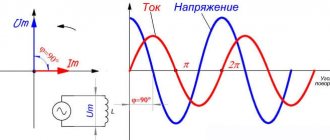
The coil with the winding stores the energy of the magnetic field with its turns. Thanks to the process of its accumulation, the inductive reactance moves the current vector forward by 90 degrees relative to the applied voltage on the complex plane.
By multiplying their instantaneous values, we obtain the power values, which during one period changes signs (direction) in each half-cycle.
The frequency of power changes across the inductance is twice as high as that of its components: current and voltage sinusoids. It consists of two parts:
- active, designated by the index PL;
- reactive QL.
The reactive part on the inductance is created due to the constant exchange of energy between the coil and the applied source. Its value is influenced by the value of inductive reactance XL.
How does a capacitor work?
The capacitor constantly accumulates charge between its plates. Due to this, the current vector shifts forward by 90 degrees relative to the applied voltage.
The instantaneous power graph resembles the previous one, but starts with a negative half-wave.
The reactive component released on the capacitor depends on the value of capacitance XC.
How a real circuit works with all types of resistance
In their pure form, the above graphs and expressions are not found so often. In fact, the transmission of electricity and its operation on alternating current are associated with the complex overcoming of the forces of electrical resistance of resistors, capacitors and inductances.
Moreover, some of these components will prevail. For such cases, the conversion of electrical energy into instantaneous power can be one of the following types.
The top picture shows the case when the current vector lags behind the applied voltage, and the bottom picture leads.
In both cases, the value of the active component decreases from the total value by a value expressed as cosφ. Therefore, it is commonly called power factor.
Cosine phi (cosφ) is used in analyzing the triangle of power and resistance and characterizes energy losses.
How does a three-phase power supply circuit work?
The input switchboard of a multi-storey building receives three-phase voltage from the power supply organization, generated by industrial generators.
If desired, the owner of a private house can connect it, for a fee, which is what many do. In this case, the working diagram and voltage diagram looks like this.
In the old TN-C grounding system it is made with a four-wire connection, and in the new TN-S it is made with a five-wire connection with the addition of a protective PE conductor. I do not show it in this diagram for simplicity.
During operation, each phase must be loaded with equally equal currents. Then the most favorable optimal mode will be created in the home wiring without dangerous energy imbalances.
In this case, the formula for calculating power by current and voltage for a three-phase circuit can be represented by a simple sum of similar formulas for the components of single-phase circuits.
And since they are all identical, they are simply tripled.
For example, when the active power of phase B has the expression Рв=Uв×Iв×cosφ, then for the entire three-phase circuit it will be expressed by the following formula:
P = Pa+Pv+Pc
If we mark the phase expression with the letter f. for example Pf, you can write:
P = 3Pph = 3Uph×Iph×cosφ
The reactive component will be calculated similarly
Q = Qa+Qв+Qc
Or
Q = 3Qph = 3Uph×Iph×sinφ
Since P and Q represent the dimensions of the legs of a right triangle, the hypotenuse or total component can be calculated as the square root of the sum of their squares.
S = √(P2+Q2)
How three-phase apparent power is taken into account
In the power system, and even in a private home, it is necessary to analyze the connected loads and distribute them evenly among the voltage sources.
Numerous designs of measuring instruments work for this purpose. On the control panels of substations there are panel wattmeters and varmeters designed to operate at different ratios.
Old analog instruments are shown in this picture.
In order to avoid confusion in the calculation records, different names of units have been introduced. They are designated:
- VA - (Russian), VA (international) voltampere for the full amount of power;
- W - (Russian), var (international) watt - active;
- var (Russian), var (international) - reactive.
Analog instruments measure only the active or reactive component, and the full value must be calculated using formulas.
Many modern digital devices are capable of performing this function automatically.
Pavel Victor's video tutorial complements my material. I recommend watching it.
Electrical Appliances Parameters
Every modern apartment must be equipped with electrical appliances. To connect them to the network, it is necessary to draw up a schematic diagram where the loads connected to individual lines will be distributed in coordination with each other. It is necessary to build in a circuit breaker based on the PUE to prevent emergency situations.
First, the electrical wiring parameters are clarified. Then they are checked according to the group diagram for connecting to the network of household electrical appliances.
Standard characteristics of electrical power consumption (W):
- desktop computer – 170-1,250;
- LCD TV – 120 – 265;
- laptop – 40-280;
- air conditioning – 1,200 – 2,500;
- iron – 450-1850.
To protect the network, you need an automatic machine; we choose it taking into account all the significant factors.
Automatic switch for protecting the electrical network Source vmasshtabe.ru
It is important to pay attention to loads that have increased reactive energy parameters.
What is it measured in?
The unit of measurement of electrical power is W for Russia. By international standards - W. This is the energy provided per unit of time. One W is equal to a joule per second (J/s). Moreover, a joule is a unit of electrical power, a second is a unit of time.
For small values, multiple prefixes are used: “milli-”, “micro-”, for large values - “mega-”. For example: 5,800 W = 5.8 kilowatts = 5.8 kW.
When you multiply 1 Kilowatt by 1 hour, you get a Kilowatt-hour (kW x h). This is a unit of measurement of the amount of electricity provided to subscribers. It is used by energy enterprises that own the appropriate equipment (generators and transformer substations). They generate and convert the produced electricity, which is then distributed to consumers.
In the same way, the energy capacity of batteries is measured in units of ampere hours (Ah). Portable types of energy storage batteries are measured in milliampere hours (mAh).
The energy in batteries is measured in milliamp hours (mAh). Source listtopa.ru
For the unit of measurement Watt, according to international standards, the letter designation W is allocated after James Watt. He was the first to use the term “horsepower,” which today is an obsolete unit of the W parameter.
Energy conversion indicators:
- horsepower (HP) - 746 W;
- kilo Watts (kW) – 1×1000 W;
- megawatts (MW) −1×1000000 W;
- gigawatt (GW) – 1×1000000000 W.
Today, "horsepower" is used to indicate the second measure of engine power in vehicles.
What is direct current
Direct electric current is a current that does not change its direction and magnitude over time. This is a kind of unidirectional DC. Its power is a value that shows the work it does as a result of moving a charge over a certain distance per unit time. It is measured, like a mechanical or light value, in watts.
Graphs of different types of electrical currents
As for distance, this fact can be omitted, since charges in a conductor can move at very high speeds, covering enormous distances.
A constant flow of charges does not change its value over time
What determines the load of electric current?
Existing electrical wiring lines experience resistance during the movement of electrons, which characterizes voltage loss. Circuits where an alternating current source is present have one feature - the key role here is played by a sinusoidal oscillation of electrical indicators.
Sinusoidal oscillation of electrical indicators. Source urpsvet.ru
The following information will allow you to select the best calculation method based on actual network conditions.
Instantaneous electrical power: calculating the value
This indicator establishes the instantaneous values of the measured data. The key definition is considered taking into account the fact that a single simple charge (q) moves in a certain time Δt. To perform a specific action, the energy of electric current PF1-F2 = U/ Δt or (U/ Δt) x q = U x (q/ Δt) is expended. The formula takes into account the movement of q over the period Δt. Since the current, according to the classical definition, is equal to the charge moving from F1 to F2 (I = q/ Δt), the final expression is derived: PF1-F2 = U x I.
Conditionally assuming that the time period is very short, we obtain the instantaneous power for part of the electrical circuit P(t) = U(t) x I(t). The same conclusions can be drawn taking into account the corresponding resistance parameter: P (t) = (I (t))2 x R = (U(t))2/ R.
Current measuring instruments
Electrical measuring instruments are a special type of devices that are used to measure many electrical quantities. These include:
- AC ammeter;
- AC voltmeter;
- Ohmmeter;
- Multimeter;
- Frequency meter;
- Electric meters.
Ammeter
To determine the current strength in an electrical circuit, you need to use an ammeter. This device is connected to the circuit in series and, due to its negligible internal resistance, does not affect its state. The ammeter scale is graduated in amperes.
In a classic device, a measured current passes through an electromagnetic coil, which creates a magnetic field that causes the magnetic needle to deflect. The deflection angle is directly proportional to the measured current.
Classic ammeter
An electrodynamic ammeter has a more complex operating principle. It contains two coils: one is movable, the other stands still. They can be connected to each other in series or in parallel. When current passes through the coils, their magnetic fields begin to interact, which as a result causes the moving coil with an arrow attached to it to deviate by a certain angle proportional to the magnitude of the current being measured.
Voltmeter
A voltmeter is used to determine the voltage (potential difference) across a section of the circuit. The device must be connected parallel to the circuit and have high internal resistance. Then only hundredths of the current will enter the device.
School voltmeter
The principle of operation is that inside the voltmeter there is a coil and a series-connected resistor with a resistance of at least 1 kOhm, on which the volt scale is calibrated. The most interesting thing is that the resistor actually registers the current strength. However, the divisions are selected in such a way that the readings correspond to the voltage value.
Ohmmeter
This device is used to determine electrically active resistance. The principle of operation is to change the measured resistance into a voltage directly dependent on it thanks to an operational amplifier. The desired object must be connected to a feedback circuit or to an amplifier.
If the ohmmeter is electronic, then it will work on the principle of measuring the current flowing through the required resistance at a constant potential difference. All elements are connected in series. In this case, the current strength will have the following dependence:
I = U/(r0 + rx),
where U is the emf of the source, r0 is the resistance of the ammeter, rx is the desired resistance. According to this dependence, resistance is determined.
Electronic ohmmeter
Multimeter
The devices given as an example are used today only in schools for physics lessons. Multimeters were invented for professional tasks. The most common device includes simultaneously the functions of an ammeter, voltmeter and ohmmeter. The device can be either easily portable or huge stationary with a large number of possibilities. The name “multimeter” was first applied specifically to a digital meter. Analog devices are more often called “avometer”, “tester” or simply “Tseshka”.
Universal multimeter
The work of current is a complex but very important topic in electrodynamics. Without knowing it, you will not be able to solve even the simplest problems. Even electricians use job finding formulas to make the necessary calculations.
Electrical power: DC circuit
The previously mentioned formulas are shown without correction factors. They are used to calculate a circuit connected to a direct current source. Using an ordinary device - a multimeter, with the switch in the correct position, the resistance of the load connected to the network is set.
With its help, the load resistance is set. Source hammer-shop.ru
What factors influence current power
Direct current is affected by only two quantities: the strength of the electric current (in amperes) and the voltage (in volts). From the formula described above, it becomes clear that the power characteristic of a constant electric current is calculated as the product of the electric current in this network and the voltage.
Note! If a source of electromotive forces is connected to the circuit, P will also depend on it, and to be more precise, it will be measured as the current strength multiplied by the emf.
You might be interested in this: Features of SMD markings
Electrical power: AC circuit
For such lines, it is unacceptable to use formulas that determine instantaneous parameters, since the final indicator changes from a minimum value to a maximum value with the network frequency. A typical single-phase 220 V network is characterized by a 50 Hz sinusoidal signal. It is allowed to use the simple formula P = U x I when connecting devices with resistive parameters:
- Heating elements of washing machines;
- spirals of infrared heaters;
- incandescent light bulbs.
Using this formula, the load is set.
Energy can be of two types: reactive and active.
Active is the true electrical power that produces real work in the load, W shows this parameter. It converts energy into mechanical, thermal and other forms.
If you turn on a powerful unit or capacitor, the voltage inside the network drops. Such loads create an oscillating circuit that receives energy from the power source. In this situation, only P act components perform useful functions. The active indicator is calculated in the following way:
- U x I – direct current (alternating current with a resistive load);
- U x I x cos fi – for a single-phase 220 V line;
- U x √3 x cos fi = U x 1.7321 x cos fi – 3-phase network, U x √3 x 380V.
There are other types of energy, but more on that later.
Active and passive energy Source ppt-online.org
Reactive power
This indicator shows the loads that are created in devices due to fluctuations in the energy of the electromagnetic field.
Reactive power, regardless of the absence of useful work, must be taken into account to correctly evaluate key network data. Cables and wires, when current passes through them in any direction, heat up. This happens quite cyclically. Energy effects at high intensity:
- damage cable cores and protective insulation;
- contribute to the occurrence of a short circuit;
- destroy the windings of transformers and drives.
Reactive power is expressed as VA (volt-amperes) and is calculated by multiplying the voltage by the current and the shear angle:
P r = U x I x sin fi.
When connecting a load with capacitive parameters, the value becomes negative, when inductive it becomes positive. Since the characteristics of the magnetic field change, the unit of measurement for reactive power is VA.
If the parameters of total electrical power are shown as vectors, a triangle appears. The length of its sides will be equal to the amount of electricity consumed by a particular component. The angle between the apparent power (Pap) and the active power (ϕ) is used for calculations. The total value is determined by the expression: P total = √((P act)2 + (P react)2).
Basic concepts of quantities
Electrical calculations are based on well-known relationships between current (I, Ampere), voltage (U, Volt), power value (P, Watt) and resistance (R, Ohm). Practical calculations usually require knowledge of the values of the first three.
We warn you that numerical expressions of the listed values are not enough - additional characteristics are needed that reveal the power consumption mode.
Electric current strength
The calculation of the sufficient cross-section of the conductors and the rating of the circuit breaker for a specific branch of the electrical network is carried out according to the value of the maximum possible current strength for this section. This is necessary to prevent the wiring from catching fire, which often results in a fire.
The operating parameters of machines and RCDs are selected according to regulatory requirements. To determine the permissible cross-section of the cores depending on the maximum possible current strength, it is necessary to use the table provided by the product manufacturer, because the cables are most often produced according to specifications, and not according to GOST.
Having the same markings, cables produced in accordance with GOST (left) and TU (right) differ both visually and in basic characteristics
Since the strength of the electric current can be calculated based on the power consumed by the devices and the network voltage, it is necessary to correctly determine the values of these two indicators.
Household voltage
Many apartment owners believe that the standard phase voltage for household needs is approximately 220 V. In most cases, this is true. Although, according to GOST 29322-2014, from October 1, 2015, within the Russian Federation there should have been a transition to a 230 V system compatible with the EEC countries.
A deviation of 5% from the standard is acceptable for any period, and 10% for a period not exceeding 1 hour. Thus, according to the old rules, the voltage value can fluctuate in the range from 198 to 242 V, and according to the current GOST - from 207 to 253 V.
There are also cases when the voltage in the network for a long time is significantly lower than the standard one. This situation arises when the total power of electrical appliances connected to the branch is much higher than planned and when most of them are turned on, a “network drawdown” occurs.
This problem occurs in the area of responsibility of organizations responsible for the supply of electricity, and is associated with overloading of distribution transformers, deterioration of substations or insufficient wire cross-section.
A reduced input voltage leads not only to a change in the current parameter and possible tripping of the protection, but also to rapid breakdown of electrical appliances containing asynchronous electric motors or complex electronics
To find out the real voltage value, you need to periodically take measurements using a voltmeter. If the indicators fluctuate greatly, then it is necessary to use a stabilizer or a more expensive converter with an electricity storage function.
Nuances in the concept of power of electrical appliances
All devices that consume electricity have such a parameter as power. The higher this indicator, the more energy the device takes from the circuit.
There are three types of power:
- Active (P). Characterizes the rate of conversion of electrical energy into another form, for example electromagnetic or thermal. It must be taken into account when calculating the irreversible costs of electricity, and therefore the cost of operating the device. Unit of measurement – W.
- Reactive (Q). Characterizes the energy that comes from the source (transformer) to the reactive elements of the consumer (capacitors, motor windings), but then almost instantly returns to the source. The unit of measurement is W or var (interpretation is reactive volt-ampere).
- Full (S). Characterizes the load that the consumer imposes on the circuit elements. It is used when calculating the cross-sectional area of the cable and choosing the rating of the machines, that is, the current strength is calculated based on the full power of all electrical appliances connected to the circuit. The unit of measurement is W or V*A (V*A – volt amperes).
All these parameters can be recalculated through the phase angle that occurs between the voltage vector and current (f):
P = S * cos(f);
Q = S * sin(f);
S2 = P2 + Q2.
Household devices in which the total power can significantly exceed the active power include refrigerators, washing machines, fluorescent and some energy-saving lamps, as well as power electronics units.
On motors, active power and coefficient are usually indicated. In this case, the total power is calculated as follows: S = P / cos(f) = 750 / 0.78 = 962 W
There is also such a thing as peak or starting power. The fact is that accelerating engines requires much more effort than maintaining their rotation. Therefore, when you turn on appliances such as a refrigerator or washing machine, a short-term load surge occurs on a section of the circuit.
Starting currents can be several times higher than operating currents. When calculating the required cable cross-section and selecting the rating of the machine, this should be taken into account.
To do this, you need to determine the device with the greatest difference in starting and operating power and add it to the total value. The starting currents of other devices can be ignored, since the probability of simultaneous activation of motors for different consumers is practically zero.
What is power in electricity
Voltage is the work done to move a unit of charge. Current is the number of coulombs moved in 1 second. When multiplying the first parameter by the second, the total amount of work done in 1 second is obtained.
The strength of electricity is a numerical current meter that characterizes its energy qualities. The power indicator equally depends on voltage and current strength. How is current power measured? To measure this parameter, a Wattmeter is used; the unit of measurement is designated in the same way - W (Watt).
By using the dependence of the power parameter on current and voltage, specialists can transmit electricity over long distances. For these purposes, energy is converted at step-down and step-up transformer substations (transformer substations).
Electric current power measurement
You can measure the strength of electric current using a voltmeter and an ammeter. To calculate the required power, multiply the electrical voltage by the current. Electric current and voltage can be found from instrument readings.
Rice. 2. Electric current power measurement
Remember that you should always detect electrical voltage in parallel with the load and electrical current in series.
There are special devices - wattmeters - that determine the power of the electric current in a circuit, which, in fact, replace two devices - an ammeter and a voltmeter.
Electrical power and inactive power
Equipment certificates contain active load - power factor, which is an important characteristic. It shows how efficiently a household appliance consumes electricity.
Fig.8
This is a number from −1 to 1, it is never equal to one. This coefficient depends on the type of load: C, L or R. The first 2 negatively affect PF = cos φ of the system. If its parameter is large, the current consumed by the devices increases. Many power loads are inductive, causing the current to lag behind the voltage.
Inactive energy arises in electrical AC circuits of alternating current networks. It is calculated simply: the square root of the sum (Pa2 + Pr2). If the reactive load is zero, then the passive load is equal to the modulus |Pa|.
The presence of nonlinear current distortions in electrical networks is caused by non-compliance with the direction that occurs between U/I, since the energy has a pulsed nature. In nonlinear modes, the apparent current power (EP) increases. Such a load is inactive and consumes Pr and current distortion energy. The unit of measurement is the same as regular power W.
Concept of total power. Capacity Triangle
Apparent power is a geometrically calculated value equal to the root of the sum of the squares of active and reactive powers, respectively. Denoted by the Latin letter S.
You can also calculate the total power by multiplying the voltage and current respectively.
S = U⋅I
IMPORTANT! Apparent power is measured in volt-amperes (VA).
The power triangle is a convenient representation of all the previously described calculations and relationships between active, reactive and apparent power.
The legs reflect the reactive and active components, the hypotenuse – the full power. According to the laws of geometry, the cosine of the angle φ is equal to the ratio of the active and total components, that is, it is the power factor.