Electric motor power concept
Power is perhaps the most important parameter when choosing an electric motor. Traditionally, it is indicated in kilowatts (kW), for imported models - in kilowatts and horsepower (hp, HP, Horse Power). For reference: 1 hp. approximately equal to 0.75 kW.
The engine nameplate indicates the rated net (output mechanical) power
. This is the power that the engine can deliver to a mechanical load with the stated parameters without overheating. In the formulas, the rated mechanical power is denoted by P2.
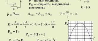
Electrical (consumption) power
motor P1 is always greater than the output P2, since there are losses in any energy conversion device. The main losses in an electric motor are mechanical, caused by friction. As you know from a physics course, losses in any device are determined through efficiency (ƞ), which is always less than 100%. In this case, the formula is valid:
Р2 = Р1 · ƞ
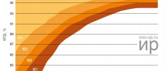
The efficiency in engines depends on the rated power - for low-power models it can be less than 0.75, for powerful ones it exceeds 0.95. The above formula is valid for active power consumption. But, since the electric motor is an active-reactive load, to calculate the total power consumption S
(taking into account the reactive component) it is necessary to take into account reactive losses. The reactive component is expressed in terms of power factor (cosϕ). Taking this into account, the formula for the rated engine power looks like this:
Р2 = Р1 · ƞ = S · ƞ · cosϕ
Variations of electric motors according to climate control
When selecting an electric motor, you need to know what climatic conditions this motor will be used in.
The designations for different climate versions are listed below:
- U – Temperate climate;
- HL - Cold climate;
- TC – Tropical Dry climate;
- TV – Tropical Humid Climate;
- T – Tropical climate (generalized);
- M – Maritime climate;
The digital value after the letter designation of the brand indicates the type of its placement:
- 1 – work on the “street”;
- 2 – work on the “street”, but under a canopy;
- 3 – work indoors;
Engine power and heating
The rated power is usually specified for an ambient temperature of 40°C and is limited by the maximum heating temperature. Since the weakest point in a motor in terms of overheating is insulation, power is limited by the insulation class of the stator winding. For example, for the most common insulation class F, the permissible heating is 155°C at an ambient temperature of 40°C.
The documentation for electric motors provides data that shows that the rated power of the motor drops as the ambient temperature rises. On the other hand, with proper cooling, engines can operate at higher than rated power for a long time.
We have looked at the power consumption and output, but it should be said that the actual operating power consumption P
(motor shaft power at a given moment) should always be less than rated:
R 2 1
This is necessary to prevent engine overheating and to have an overload reserve. Short-term overloads are permissible, but they are limited primarily by engine heating. It is also advisable to install motor overload protection not based on the rated current (which is directly proportional to power), but based on the actual operating current.
Modern manufacturers mainly produce engines from a number of ratings: 1.5, 2.2, 5.5, 7.5, 11, 15, 18.5, 22 kW, etc.
Early developments
In 1821, after the discovery of the phenomenon of the connection between electricity and magnetism by the Danish chemist Oersted, Ampere’s theorem and Biot-Savart’s law, the English physicist Michael Faraday built two devices, which he called “electromagnetic rotation”: the continuous circular movement of the magnetic force around the wire is the actual demonstration of the first electric motor.
In 1822, Peter Barlow built what can be considered the first electric motor in history: the Barlow wheel. This device consists of a simple metal disk cut into a star, the ends of which are immersed in a cup containing mercury, providing a flowing stream. However, it only creates a force capable of turning it, preventing its practical use.
The first experimentally used commutator was invented in 1832 by William Sturgeon. The first commercially manufactured DC motor was invented by Thomas Davenport in 1834 and patented in 1837. These engines did not experience any industrial development due to the high cost of batteries at the time.
Electric motor with DC
A DC switched apparatus has a set of rotating windings wound around an armature mounted on a rotating shaft. The shaft also contains a commutator, a long-lasting rotary electrical switch that periodically changes the flow of current in the rotor windings as the shaft rotates. Thus, each DC bridge motor has alternating current passing through the rotating windings. Current flows through one or more pairs of brushes that are carried on the commutator; brushes connect an external power source to the rotating armature.
A rotating armature consists of one or more spools of wire wound around a laminated ferromagnetic core. The current from the brush flows through the commutator and one armature winding, making it a temporary magnet (electromagnet). The magnetic field produced by the armature interacts with the stationary magnetic field produced by either the PM or another winding (field coil) as part of the motor frame.
The force between the two magnetic fields tends to rotate the motor shaft. The commutator switches power to the coils as the rotor turns, keeping the magnetic poles from ever completely matching the stator's magnetic poles so that the rotor never stops (like a compass needle), but rather rotates as long as there is power.
Although most switches are cylindrical, some are flat disks consisting of several segments (usually at least three) mounted on an insulator.
Large brushes are desirable for a larger brush contact area, to maximize motor power, but small brushes are desirable for low mass, to maximize the speed at which the motor can operate without excessive kickback and brush sparking. Stiffer brush springs can also be used to produce brushes of a given mass at higher speeds, but at the expense of greater friction and wear on the accelerated brush and commutator. Therefore, DC motor design entails a trade-off between power output, speed, and efficiency/wear.
Design of DC motors:
- The valve circuit is a winding; it carries the load current, which can be a stationary or rotating part of an engine or generator.
- Field circuit - a set of windings that create a magnetic field so that electromagnetic induction can exist in electrical machines.
- Switching. A mechanical technique in which rectification can be achieved, or whereby direct current can be obtained.
There are four main types of DC motors:
- Electric motor with shunt winding.
- DC motor.
- Combined engine.
- Engine PM.
Engine power calculation based on measurements
In practice, the motor power can be calculated primarily from the operating current. The current is measured by current clamps in the maximum operating mode, when the operating power approaches the rated power. In this case, the temperature of the motor housing can exceed 100 °C, depending on the heat resistance class of the insulation.
We substitute the measured current into the formula to calculate the real mechanical power
on the shaft:
P = 1.73 U I cosϕ ƞ
, Where
- U – supply voltage (380 or 220 V, depending on the connection diagram - “star” or “delta”),
- I – measured current,
- cosϕ and ƞ – power factor and efficiency, the values of which can be taken equal to 0.8 for low-power motors (less than 5.5 kW) or 0.9 for motors with a power of more than 15 kW.
If you need to find the rated power
engine, then the resulting result is rounded up to the nearest value from the range of denominations.
P2 > P
If you need to calculate the active power consumption
, we use the following formula:
P1 = 1.73 U I ƞ
It is the active power that electricity meters measure. In industry, additional equipment is used to measure reactive (and apparent power S). With this method, you can not use the above formula, but do it in a simpler way - if the motor is connected to a “star”, we multiply the measured current value by 2 and get the approximate power in kW.
Electric motor torque table
This table contains the torques of the most common AIR electric motors in Ukraine, as well as the required starting moment - starting, the maximum permissible for a given type of electric motor - the maximum torque and moment of inertia of AIR motors (force is important when selecting an electromagnetic brake, for example)
| Engine | kW/rev | Mnom, Nm | Mstart, Nm | Mmax, Nm | Minn, Nm |
| AIR56A2 | 0,18/2730 | 0,630 | 1,385 | 1,385 | 1,133 |
| AIR56V2 | 0,25/2700 | 0,884 | 1,945 | 1,945 | 1,592 |
| AIR56A4 | 0,12/1350 | 0,849 | 1,868 | 1,868 | 1,528 |
| AIR56V4 | 0,18/1350 | 1,273 | 2,801 | 2,801 | 2,292 |
| AIR63A2 | 0,37/2730 | 1,294 | 2,848 | 2,848 | 2,330 |
| AIR63V2 | 0,55/2730 | 1,924 | 4,233 | 4,233 | 3,463 |
| AIR63A4 | 0,25/1320 | 1,809 | 3,979 | 3,979 | 3,256 |
| AIR63V4 | 0,37/1320 | 2,677 | 5,889 | 5,889 | 4,818 |
| AIR63A6 | 0,18/860 | 1,999 | 4,397 | 4,397 | 3,198 |
| AIR63V6 | 0,25/860 | 2,776 | 6,108 | 6,108 | 4,442 |
| AIR71A2 | 0,75/2820 | 2,540 | 6,604 | 6,858 | 4,064 |
| AIR71V2 | 1,1/2800 | 3,752 | 8,254 | 9,004 | 6,003 |
| AIR71A4 | 0,55/1360 | 3,862 | 8,883 | 9,269 | 6,952 |
| AIR71V4 | 0,75/1350 | 5,306 | 13,264 | 13,794 | 12,733 |
| AIR71A6 | 0,37/900 | 3,926 | 8,245 | 8,637 | 6,282 |
| AIR71V6 | 0,55/920 | 5,709 | 10,848 | 12,560 | 9,135 |
| AIR71V8 | 0,25/680 | 3,511 | 5,618 | 6,671 | 4,915 |
| AIR80A2 | 1,5/2880 | 4,974 | 10,943 | 12,932 | 8,953 |
| AIR80V2 | 2,2/2860 | 7,346 | 15,427 | 19,100 | 13,223 |
| AIR80A4 | 1,1/1420 | 7,398 | 16,275 | 17,755 | 12,576 |
| AIR80V4 | 1,5/1410 | 10,160 | 22,351 | 24,383 | 17,271 |
| AIR80A6 | 0,75/920 | 7,785 | 16,349 | 17,128 | 12,457 |
| AIR80V6 | 1,1/920 | 11,418 | 25,121 | 26,263 | 20,553 |
| AIR80A8 | 0,37/680 | 5,196 | 10,393 | 11,952 | 7,275 |
| AIR80V8 | 0,55/680 | 7,724 | 15,449 | 16,221 | 10,814 |
| AIR90L2 | 3/2860 | 10,017 | 23,040 | 26,045 | 17,030 |
| AIR90L4 | 2,2/1430 | 14,692 | 29,385 | 35,262 | 29,385 |
| AIR90L6 | 1,5/940 | 15,239 | 30,479 | 35,051 | 28,955 |
| AIR90LA8 | 0,75/700 | 10,232 | 15,348 | 20,464 | 15,348 |
| AIR90LV8 | 1,1/710 | 14,796 | 22,194 | 32,551 | 22,194 |
| AIR100S2 | 4/2850 | 13,404 | 26,807 | 32,168 | 21,446 |
| AIR100L2 | 5,5/2850 | 18,430 | 38,703 | 44,232 | 29,488 |
| AIR100S4 | 3/1410 | 20,319 | 40,638 | 44,702 | 32,511 |
| AIR100L4 | 4/1410 | 27,092 | 56,894 | 65,021 | 43,348 |
| AIR100L6 | 2,2/940 | 22,351 | 42,467 | 49,172 | 35,762 |
| AIR100L8 | 1,5/710 | 20,176 | 32,282 | 40,352 | 30,264 |
| AIR112M2 | 7,5/2900 | 24,698 | 49,397 | 54,336 | 39,517 |
| AIR112M4 | 5,5/1430 | 36,731 | 73,462 | 91,827 | 58,769 |
| AIR112MA6 | 3/950 | 30,158 | 60,316 | 66,347 | 48,253 |
| AIR112MV6 | 4/950 | 40,211 | 80,421 | 88,463 | 64,337 |
| AIR112MA8 | 2,2/700 | 30,014 | 54,026 | 66,031 | 42,020 |
| AIR112MV8 | 3/700 | 40,929 | 73,671 | 90,043 | 57,300 |
| AIR132M2 | 11/2910 | 36,100 | 57,759 | 79,419 | 43,320 |
| AIR132S4 | 7,5/1440 | 49,740 | 99,479 | 124,349 | 79,583 |
| AIR132M4 | 11/1450 | 72,448 | 173,876 | 210,100 | 159,386 |
| AIR132S6 | 5,5/960 | 54,714 | 109,427 | 120,370 | 87,542 |
| AIR132M6 | 7,5/950 | 75,395 | 150,789 | 165,868 | 120,632 |
| AIR132S8 | 4/700 | 54,571 | 98,229 | 120,057 | 76,400 |
| AIR132M8 | 5,5/700 | 75,036 | 135,064 | 165,079 | 105,050 |
| AIR160S2 | 15/2940 | 48,724 | 97,449 | 155,918 | 2,046 |
| AIR160M2 | 18,5/2940 | 60,094 | 120,187 | 192,299 | 2,884 |
| AIR180S2 | 22/2940 | 71,463 | 150,071 | 250,119 | 4,288 |
| AIR180M2 | 30/2940 | 97,449 | 214,388 | 341,071 | 6,821 |
| AIR200M2 | 37/2950 | 119,780 | 275,493 | 383,295 | 16,769 |
| AIR200L2 | 45/2940 | 146,173 | 380,051 | 584,694 | 19,003 |
| AIR225M2 | 55/2955 | 177,750 | 408,824 | 710,998 | 35,550 |
| AIR250S2 | 75/2965 | 241,568 | 628,078 | 966,273 | 84,549 |
| AIR250M2 | 90/2960 | 290,372 | 784,003 | 1161,486 | 116,149 |
| AIR280S2 | 110/2960 | 354,899 | 887,247 | 1171,166 | 212,939 |
| AIR280M2 | 132/2964 | 425,304 | 1233,381 | 1488,563 | 297,713 |
| AIR315S2 | 160/2977 | 513,268 | 1231,844 | 1693,786 | 590,259 |
| AIR315M2 | 200/2978 | 641,370 | 1603,425 | 2116,521 | 962,055 |
| AIR355SMA2 | 250/2980 | 801,174 | 1281,879 | 2403,523 | 2163,171 |
| AIR160S4 | 15/1460 | 98,116 | 186,421 | 284,538 | 7,457 |
| AIR160M4 | 18,5/1460 | 121,010 | 229,920 | 350,930 | 11,375 |
| AIR180S4 | 22/1460 | 143,904 | 302,199 | 402,932 | 15,110 |
| AIR180M2 | 30/1460 | 196,233 | 470,959 | 588,699 | 27,276 |
| AIR200M4 | 37/1460 | 242,021 | 532,445 | 847,072 | 46,952 |
| AIR200L4 | 45/1460 | 294,349 | 647,568 | 941,918 | 66,229 |
| AIR225M4 | 55/1475 | 356,102 | 997,085 | 1317,576 | 145,289 |
| AIR250S4 | 75/1470 | 487,245 | 1218,112 | 1559,184 | 301,605 |
| AIR250M4 | 90/1470 | 584,694 | 1461,735 | 1871,020 | 467,755 |
| AIR280S4 | 110/1470 | 714,626 | 2072,415 | 2429,728 | 578,847 |
| AIR280M4 | 132/1485 | 848,889 | 1697,778 | 2886,222 | 1612,889 |
| AIR315S4 | 160/1487 | 1027,572 | 2568,931 | 3802,017 | 2363,416 |
| AIR315M4 | 200/1484 | 1287,062 | 3217,655 | 4247,305 | 3603,774 |
| AIR355SMA4 | 250/1488 | 1604,503 | 3690,356 | 4492,608 | 8985,215 |
| AIR355SMВ4 | 315/1488 | 2021,673 | 5054,183 | 5862,853 | 12534,375 |
| AIR355SС4 | 355/1488 | 2278,394 | 5012,466 | 6151,663 | 15493,078 |
| AIR160S6 | 11/970 | 108,299 | 205,768 | 314,067 | 12,021 |
| AIR160M6 | 15/970 | 147,680 | 339,665 | 443,041 | 20,675 |
| AIR180M6 | 18,5/970 | 182,139 | 400,706 | 546,418 | 29,324 |
| AIR200M6 | 22/975 | 215,487 | 517,169 | 711,108 | 50,209 |
| AIR200L6 | 30/975 | 293,846 | 617,077 | 881,538 | 102,846 |
| AIR225M6 | 37/980 | 360,561 | 721,122 | 1081,684 | 186,050 |
| AIR250S6 | 45/986 | 435,852 | 784,533 | 1307,556 | 440,210 |
| AIR250M6 | 55/986 | 532,708 | 1012,145 | 1811,207 | 633,922 |
| AIR280S6 | 75/985 | 727,157 | 1454,315 | 2326,904 | 1090,736 |
| AIR280M6 | 90/985 | 872,589 | 1745,178 | 2792,284 | 1657,919 |
| AIR315S6 | 110/987 | 1064,336 | 1809,372 | 2873,708 | 4044,478 |
| AIR315M6 | 132/989 | 1274,621 | 2166,855 | 3696,400 | 5735,794 |
| AIR355MA6 | 160/993 | 1538,771 | 2923,666 | 3539,174 | 11848,540 |
| AIR355MV6 | 200/993 | 1923,464 | 3654,582 | 4423,968 | 17118,832 |
| AIR355MLA6 | 250/993 | 2404,330 | 4568,228 | 5529,960 | 25485,901 |
| AIR355MLB6 | 315/992 | 3032,510 | 6065,020 | 7278,024 | 40029,133 |
| AIR160S8 | 7,5/730 | 98,116 | 156,986 | 235,479 | 13,246 |
| AIR160M8 | 11/730 | 1007,329 | 1712,459 | 2417,589 | 181,319 |
| AIR180M8 | 15/730 | 196,233 | 333,596 | 529,829 | 41,994 |
| AIR200M8 | 18,5/728 | 242,685 | 509,639 | 606,714 | 67,952 |
| AIR200L8 | 22/725 | 289,793 | 579,586 | 724,483 | 88,966 |
| AIR225M8 | 30/735 | 389,796 | 701,633 | 1052,449 | 214,388 |
| AIR250S8 | 37/738 | 478,794 | 861,829 | 1196,985 | 481,188 |
| AIR250M8 | 45/735 | 584,694 | 1052,449 | 1520,204 | 695,786 |
| AIR280S8 | 55/735 | 714,626 | 1357,789 | 2143,878 | 1071,939 |
| AIR280M8 | 75/735 | 974,490 | 1754,082 | 2728,571 | 1851,531 |
| AIR315S8 | 90/740 | 1161,486 | 1509,932 | 2671,419 | 4413,649 |
| AIR315M8 | 110/742 | 1415,768 | 2265,229 | 3964,151 | 6370,957 |
| AIR355SMA8 | 132/743 | 1696,635 | 2714,616 | 3902,261 | 12215,774 |
| AIR355SMB8 | 160/743 | 2056,528 | 3496,097 | 4935,666 | 18097,443 |
| AIR355MLA8 | 200/743 | 2570,659 | 4627,187 | 6940,781 | 26991,925 |
| AIR355MLB8 | 250/743 | 4498,654 | 7647,712 | 10796,770 | 58032,638 |
Torque calculation - formula
Note: when calculating, it is worth taking into account the slip coefficient of the asynchronous motor. The nominal engine speed does not match the real one. You can find the exact number of revolutions, knowing the markings, in the table above.
Online calculation
To calculate the electric motor torque online, enter the motor power value and the actual angular velocity (rpm)
there will be a calculator here
After calculating the torque, look at the connection diagrams for asynchronous electric motors with star and delta on the Slobozhansky Plant website
Power calculation using an electricity meter
This method is simple and does not require additional tools or knowledge. It is enough to connect the motor through a meter (three-phase metering unit) and find out the difference in readings over a strictly defined time. For example, when the engine is running for an hour, the difference in the meter readings will be numerically equal to the active power of the engine (P1). But to get the rated power P2, you need to use the above formula.
Other useful materials:
Degrees of protection IP Three-phase motor in a single-phase network Typical faults of electric motors
Advantages of diesel generators:
• High power. Indicators can vary from 3 to 200 kW and above, when gasoline engines have a maximum result of 18 kW. • The motor differs in domestic and professional installations. For the first type of equipment, the time between failures reaches 300-400 hours, for the second - up to 5,000 hours. • Automatic stabilization of the produced voltage. On the modern market there are models with a regulator that controls engine speed. It allows the generator to independently adapt the voltage when surges occur to the stated user requirements. • Efficiency indicator reaches 50%. • Long motor life. Generators operate without interruption for a long time, therefore they act as an additional and main power source. • The installation can be used in enterprises to ensure stable operation - this will avoid violations of technical processes that cause defects. • There are practically no restrictions on the ambient temperature. Climatic conditions do not in any way affect the operation of the generator if the temperature varies from -40°C to +40°C and the humidity does not exceed 95%. • New models of diesel generators are equipped with a noise-insulating housing, so they operate relatively silently.
Determination of shaft speed
Three-phase asynchronous motors are divided into 4 types based on rotor speed: 3000, 1500, 1000 and 750 rpm. min. Here is an example of marking based on AIR 180:
The easiest way to determine the number of revolutions of a three-phase asynchronous electric motor is to remove the rear casing and look at the stator winding.
For a 3000 rpm engine, the stator winding coil occupies half a circle - 180 °, that is, the beginning and end of the section are parallel to each other and perpendicular to the center. For electric motors at 1500 rpm the angle is 120°, at 1000 rpm it is 90°. A schematic view of the coils is shown in the drawing. See the table for all motor winding data.
Find out the rotation speed using an ammeter
You can find out the motor shaft speed by counting the number of poles. To do this, we need a milliammeter - we connect the measuring device to the stator winding. When the motor shaft rotates, the ammeter needle will deviate. The number of needle deflections per revolution is equal to the number of poles.
Selecting an electric motor and calculating its operating parameters.
As a result, it is usually expressed in millinewtons times meters (mN • m). 1000 mN • m to 1 N • m, so the calculated torque is 1.26 mN • m. This could be further converted to (g-cm) by multiplying the result by 10.2, and. e. The torque is 12.86 g-cm.
Expert opinion
It-Technology, Electrical power and electronics specialist
Ask questions to the “Specialist for modernization of energy generation systems”
Find out the power of an electric motor by the diameter of the shaft without a tag. You can determine the power of the motor by comparing the overall dimensions with the table for determining the power of the electric motor by clicking on the link overall and connecting dimensions of AIR electric motors. Ask, I'm in touch!