Author: Sergey Kurtov
Reading time: 5 min
Publication date: 02/18/2022
Article rating: (2)
In the home of every resident of Ukraine there are many units of household appliances and electronics. Each electrical appliance has certain requirements for input voltage and, as a rule, these requirements largely coincide. In accordance with GOST, for the correct operation of certified single-phase household appliances and electronics, 220V power is required with a deviation of no more than 10% or 22V. In practice, the operating range within which the equipment maintains correct operation is somewhat wider. Thus, the installed equipment determines what voltage is needed for a private home.
It's no secret that the mains voltage floats all the time, which may be caused by changes in the degree of load, physical impact on power lines, the condition of substations and other factors independent of the end user. We cannot influence them, therefore an emergency situation accompanied by a voltage surge can cause the failure of one or several electrical appliances at once. Such a prospect. Many people do not care about this problem, so they count on the fact that no emergency situation will happen, and if it does happen, then by a happy coincidence the equipment will be turned off. However, when another electrical appliance breaks down, few people think that the cause may be network fluctuations.
The simplest solution to the problem is a voltage stabilizer. We will look at how to calculate the power of a voltage stabilizer for a home and which models to pay attention to so as not to overpay for excessive characteristics.
Algorithm for calculating stabilizer power
When selecting the required voltage stabilizer model, its incorrectly calculated power can lead to the following consequences:
- a stabilizer with an output power less than required will constantly turn off or not start at all, and possibly fail;
- purchasing a device with a power much higher than the required value will be a waste of money. The device will be underloaded during operation, which will reduce its efficiency.
To determine the current stabilizer power and correctly select the appropriate model, we recommend following an algorithm consisting of three steps:
- Find out the load power.
- Add the margin to the value of the power consumed by the load.
- Select a suitable stabilizer model based on the final value.
Let's look at the three points mentioned above and analyze the most common mistakes that accompany each of them.
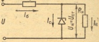
↑ Second option for calculating the parametric stabilizer [3 - 5]
uses the limit values of the load current In min and In max as initial data, which, when In min = 0, makes it possible to provide for the idle mode of the stabilizer. For constant load choose In max = In min.
So, the initial data are: stabilized load voltage Uout, load currents In min, In max, rated input voltage Uin and its deviations ΔUin n and ΔUin in.
The parameters of the zener diode are the same as in the previous calculation: Ust = Uout, Ist max, Ist min, rd.
We calculate the maximum and minimum values of the zener diode operating current:
Ist p max=0.8 Ist max, Ist p min=1.2 Ist min.
If the stabilizer must operate in idle mode (In min=0), select Ist p min=Ist min.
We check the suitability of the zener diode selected for stabilization voltage within the specified limits of the load current and supply voltage:
(Ist p max+ In min)(1- ΔUin n)-(Ist min+ In max)(1+ ΔUin in)>0, where ΔUin n=(Uin-Uin min)/ Uin, ΔUin in=(Uin max-Uin )/Uin.
If the inequality is not satisfied, you need to: • use a more powerful zener diode; • set smaller values of ΔUin n and ΔUin in; • reduce In max or increase In min.
The rated voltage Uin, which the rectifier must provide, is calculated using the formula:
Uin= Ust [(Ist p max+I n min)- (Ist p min+ I n max)]/[(Ist p max+I n min)(1- ΔUinn)- (Ist p min+I n max) (1+ΔUin in)].
Ballast resistor resistance:
R0= Uin(ΔUin in+ΔUin n)/[(Ist p max+ In min)- (Ist p min+ In max)].
We also calculate the power of the resistor with a double margin:
Po=2(Uin(1+ ΔUin n)- Ust)2/R0.
Using the formulas given in the first version of the calculation, we find Kst, efficiency and Kf.
↑ Calculation example No. 3
Let's calculate a parametric voltage stabilizer with the following characteristics: stabilized load voltage Un=9 V;
current In min =0, In max =10 mA; change in input ΔUin n=10%, ΔUin v=15%. Let's choose a zener diode of type D814B, for which Ust = Un; rd=10 Ohm; Ist max=36 mA, Ist min=3 mA.
After entering the initial data into the “Second calculation option” table sheet, we obtain the following results (Fig. 4):
Uin=14 V, R0=221 Ohm, Po=0.45 W, Kst=14.2.
Rice. 4. Screenshot of the parametric stabilizer in idle mode
We choose a resistor with a resistance of 220 Ohms and a power of 0.5 W.
Find out the power connected to the load stabilizer
The load power is equal to the sum of the powers of all devices connected to the stabilizer. Before calculating the total power value, it is necessary to find out the energy consumption of each consumer. This is very simple to do: the power of electrical appliances is usually indicated in the technical documentation and is duplicated on the nameplate attached to the product.
Despite the apparent simplicity of the action, at this stage you can make several serious mistakes, which will entail choosing a stabilizer that is not suitable for your tasks.
Particular attention should be paid to equipment for which several capacities are indicated: pumps, heating, sound, climate control equipment, etc. It is important to distinguish between electrical power and the power produced by the product when performing its direct tasks, for example, thermal power for heating boilers, cooling power for air conditioners, sound power for audio systems.
Note!
When choosing a stabilizer, you should rely solely on the amount of power consumed by the load from the mains! In the passport of an electrical appliance, this parameter may be called: “power consumption”, “connecting power”, “electric power”, etc. All of the above is a reflection of one quantity - active power, which is measured in Watts (W or W).
Note!
Manufacturers of stabilizers usually build their range of stabilizers based on another quantity - total power, which is measured in Volt-Amps (VA or VA). It is important to understand that Watts and Volt-Amps are not the same thing, and therefore 1000 W is not equal to 1000 VA!
For electrical appliances that contain capacitive components or electric motors, the active and apparent power can vary significantly. Therefore, purchasing a stabilizer designed for 1000 VA with a load of 1000 W may be the wrong decision - the device will be overloaded with all the ensuing consequences.
To avoid this error, you should convert Watts to Volt-Amps and analyze not only the active, but also the total load power. Conversion from Watts to Volt-Amps is carried out by dividing the value in Watts by a special parameter - power factor or cos(φ): VA=W/cos(φ).
Cos(φ) reflects the dependence of the active power of the device on the total. The closer the cos(φ) value is to unity, the less energy is dissipated in the form of electromagnetic radiation and the more is converted into useful work.
The numerical value of cos(φ) is usually (but not always) indicated in the technical documentation of the device consuming alternating current (may be designated as “cos(φ)”, “Power Factor” or “PF”). If the manufacturer has not provided information about the power factor of its product, then for household appliances it is acceptable to take cos(φ) in the range of 0.7-0.8, except for devices that convert electricity into light and heat (incandescent lamps, electric kettles, irons, etc.). etc.), for them the range of power factor values is 0.9-1.
Modern technology, primarily computers, is often equipped with a power supply with power factor correction, which brings this parameter closer to unity - 0.95-0.99. If there is no confidence in the presence of such a function (denoted “PFC” or “KKM”), then for cos(φ) it is recommended to use the value from the typical range indicated in the previous paragraph.
The total load power should be calculated using only the power factor of the equipment corresponding to that load, and not using the input power factor of the stabilizer!
Note!
Devices that have an electric motor in their design are characterized by high starting currents. This category includes: pumps, washing machines and dishwashers, refrigerators, air conditioners, machine tools and compressors. The amount of energy consumed from the electrical network at the moment of turning on any of the above-mentioned devices can be several times higher than the value characteristic of the nominal operating mode.
Manufacturers of this equipment sometimes list the maximum power consumption directly in the characteristics of each model, and sometimes vice versa - they give only the nominal power value, trying not to draw attention to inevitable current surges. We recommend that you carefully study the documentation accompanying any equipment and look for information about the actual power consumed by the device during startup and in various operating modes. The load power is determined using the highest value given for each device!
In addition to mechanisms with electric motors, high starting currents are also typical for lighting devices. And not only with halogen and incandescent lamps, but also with the recently popular LED lamps. LEDs do not have inrush currents, but most luminaires based on them are equipped with capacitors, the inclusion of which causes a sharp increase in current consumption.
When choosing a stabilizer to protect a large lighting system, it should be taken into account that the power value that occurs when such a system is started can be many times higher than the rated value.
In the end
Such a conditional current source can be used as a current stabilizer for LEDs in a car (12 V-14.4 V), using it to connect lasers to some kind of transformer or UPS with a jumping voltage of several volts, or use it in charger circuits. But, as you understand, this device can be used with any other load that requires a stable electric current. This stabilizer dissipates “extra” energy in the form of heat, which may be unacceptable in situations where the voltage difference is large and the flowing current is not small, but, for example, in conditions where the input voltage does not greatly exceed the output voltage and the stabilization current is small, why not? ?
Adding power reserve
A properly selected stabilizer should have an output power that exceeds the power required to power the load. The difference between the stabilizer power and the actual power consumption of the load is called power reserve.
The recommended margin is 30% of the load energy consumption. This value will allow:
- connect additional devices to the device during operation, the power of which was not taken into account in the initial load calculation;
- avoid overload in the event of a strong voltage drop in the electrical network.
Let us give an explanation on the second point. The fact is that the power of the stabilizer decreases when the supply voltage leaves certain limits (operating range). In particular, at 135 V in the network, instead of the declared 500 VA, the stabilizer will produce only 400 VA and, accordingly, will not be able to power the maximum load relative to its rating.
For some equipment, it is recommended to provide a power reserve of over 30%. These are, for example, air conditioners or IT equipment. In the first case, this decision is explained by an increase in the power consumed by the air conditioner during operation of the device (caused by the inevitable contamination of the filter mesh). In the second case, there is a tendency towards a constant increase in the capacity of telecommunications equipment.
↑ Analysis of the operation of a parametric stabilizer [1 – 5]
The initial data of the analysis are as follows: Un, In, ΔIn, ΔUin, R0.
Also, the analysis requires the parameters of the zener diode: Ust = Un, rd, Ist max and Ist min.
The analysis comes down to calculating the operating current of the zener diode Ist p=(Uin-Ust)/R0-In; transmission coefficient Nst = Uin/Ust; power Po of the ballast resistor, stabilization coefficient Kst, efficiency and filtration coefficient Kf.
It is important to check the operating mode of the zener diode in the stabilizer circuit, which is performed using formulas similar to those given in the first calculation option.
↑ Analysis example No. 1
Let's analyze the values of ballast resistors R3 and R4 of the compensation voltage stabilizers of the Lanzar amplifier [7-9] depending on the supply voltage used.
The stated range of amplifier supply voltages is from Up=±30 V to ±65 V, while the circuit diagram shows the resistance of the ballast resistors R0=R3=R4=2.2 kOhm (1 W) [8].
In another publication [9], it is recommended to select the resistance value of ballast resistors depending on the supply voltage of the amplifier using the formula R0=(Up-15)/I, where I=8…10 mA. Table 1 shows the calculation using the specified formula for the range of amplifier supply voltages in 5 V increments.
Initial data for analysis: stabilized load voltage Un=15 V, load current In=(15-0.5)/R5=14.5/6.8=2.13 mA, ΔIn=0.213 mA, change in input voltage ΔUin=10%.
Let's choose a zener diode 1N4744A, which has the following parameters: Ust= Un=15 V; rd=14 Ohm; Ist max=61 mA; Ist min=5 mA.
An analysis of the operation of parametric stabilizers in the Lanzar amplifier showed that the minimum stabilizer current Ist p min was selected at the limit with a margin of only 3...14% instead of the required 20% (Fig. 5).
Rice. 5. Operating modes of stabilizers in the Lanzar amplifier depending on the selected supply voltage
Using the Microsoft Excel spreadsheet data analysis tool “Parameter Selection,” we will clarify the resistance of the ballast resistors. To do this, let's go to the cell with the formula for Ist p min (cell C26
) and in the menu select
Data
-> “
What-if analysis
” ->
Parameter selection
.
Set in cell C26
value 6.0 (margin 20% of Ist min), changing the value of the cell in which the resistance of the ballast resistor is entered (
$C$15
).
We get R0=1.438 kOhm. Let's enter into this cell the nearest resistance value from the standard series R0=1.3 kOhm.
Having carried out the indicated operation in the table for all values of supply voltages, we obtain the following result (Fig. 6).
Rice. 6. Clarification of operating modes of parametric stabilizers of the Lanzar amplifier
The results of the analysis are also summarized in Table 2.
The power of resistors for amplifier supply voltages from ±30 V to ±40 V is 0.5 W, for other voltages – 1 W.
Selecting the stabilizer model
To determine the model that is suitable for power, it is necessary to compare the power range of stabilizers offered by the manufacturer with the energy consumption of the load - the nearest higher value in the power range will be the required power of the stabilizer.
Note!
Selecting a stabilizer with a power value that is closest to the power consumption of the load on the downside will either reduce the previously established power reserve, or in the worst case, will lead to the purchase of a stabilizer with output parameters that do not correspond to the load.
Note!
For a three-phase stabilizer, the load on each phase should be no more than 1/3 of the rated one. For example, a three-phase stabilizer with a rating of 6000 VA will power a three-phase load of 4200 VA (the power consumed from one phase will be 1400 VA), but connecting this load stabilizer to a separate phase of 2500 VA will cause an overload, since the maximum permissible value for one phase is: 6000 /3=2000 VA.
↑ Sources mentioned
1. Polyakov V. Theory: a little about everything // Radio, 2000, No. 12, p.
45, 46 (8.6. Voltage stabilizers); Radio, 2002, No. 12, p. 45 (Nonlinear circuits); Radio, 2003, No. 5, p. 51, 52 (Calculation of power supplies). 2. Budov A. Calculation of a parametric voltage stabilizer // Radio, 1983, No. 8, p. 30. 3. Sokolov A. Calculation of a parametric stabilizer on the PMC // Radio, 1990, No. 12, pp. 60, 61. 4. Parametric voltage stabilizers. Calculation of the simplest parametric stabilizer using a zener diode. 5. Simple voltage stabilizers and their calculation. 6. Amplifier “Green Lanzar” on N-channel MOSFETs. Balanced amplifier with quasi-complementary output. 7. Symmetrical power amplifier “Lanzar” // Radioconstructor, 2008, No. 9, p. 10 – 13. 8. Article on Interlavka - Lanzar power amplifier. 9. Powerful amplifier "Lanzar". 10. Nefedov A. Microcircuit voltage stabilizers // Radio, 2008, No. 10, p. 38 – 40 (Adjustable stabilizers); Radio, 2009, No. 4, p. 41 – 44; No. 5, p. 41 – 44; No. 6, p. 41 – 44; No. 7, p. 42 - 44 (Stabilizers with fixed output voltage). Thank you for your attention!
An example of selecting a stabilizer based on power
The stabilizer is purchased to simultaneously protect three single-phase consumers. We will not focus on the specific type of devices, let’s simply call them: consumer 1, consumer 2 and consumer 3.
According to factory data sheets:
- the rated power of consumer 1 is 600 W, consumer 2 – 130 W, consumer 3 – 700 W;
- The power factor of consumers 1 and 2 is 0.7, consumer 3 is 0.95.
Determine the load power. Let consumer 1 belong to the category of equipment characterized by the presence of high inrush currents. When calculating, we do not use its rated power, but the maximum starting power, equal to 1800 W according to the technical documentation. Using the above formula, we convert the power of each consumer from W to VA:
- 1800 / 0.7 = 2571.4 VA – for consumer 1;
- 130 / 0.7 = 185.7 VA – for consumer 2;
- 700 / 0.95 = 736.8 VA – for consumer 3.
Now let’s determine the total power consumption of the planned load in W and VA:
- 1800 + 130 + 700 = 2630 W;
- 2571.4 + 185.7 + 736.8 = 3493.9 VA.
We will make further selection of the stabilizer, taking into account that the total load power on the device will be 3493.9 VA, and the active one - 2630 W (note the difference in the values in W and VA).
Next, we determine the power reserve. Let us accept the recommended value of the power reserve as 30% of the load's energy consumption - to obtain the numerical value of the required reserve, we multiply the previously calculated total power of the planned load by 0.3:
- 2630 x 0.3 = 789 W – active power reserve;
- 34.939 x 0.3 = 1048.17 VA – full power reserve.
Therefore, the load power taking into account the reserve will be:
- 2630 + 789 = 3419 W;
- 3493.9 + 1048.17 = 4542.07 VA.
Now we will select single-phase stabilizer models with the required power to power our load (taking into account the reserve), using the standard power range of single-phase inverter stabilizers produced by Shtil Group of Companies:
| Apparent power, VA | Active power, W |
| 350 | 300 |
| 550 | 400 |
| 800 | 600 |
| 1000 | 800 |
| 1500 | 1125 |
| 2000 | 1500 |
| 2500 | 2000 |
| 3000 | 2500 |
| 3500 | 2750 |
| 5000 | 4500 |
| 7000 | 5500 |
| 8000 | 7200 |
| 10000 | 9000 |
| 12000 | 11000 |
| 15000 | 13500 |
| 20000 | 18000 |
The power closest to the calculated values is 5000 VA and 4500 W, therefore, this particular stabilizer is suitable for connecting consumer 1, consumer 2 and consumer 3.
Let's assume that consumer 1, consumer 2 and consumer 3 need to be connected not to a single-phase, but to a three-phase stabilizer. The standard power range of Shtil Group for such devices is as follows:
| Apparent power, VA | Active power, W |
| 6000 | 5400 |
| 10000 | 8000 |
| 15000 | 13500 |
| 20000 | 16000 |
A load with a total power of 4542.07 VA and an active power of 3419 W can be connected to one phase of a three-phase stabilizer with an output power of 15000 VA / 13500 W, in which a separate phase will produce a maximum of 5000 VA / 4500 W.
Load distribution, that is, connecting each consumer to a separate phase, will allow you to choose a less powerful stabilizer model. The greatest load will be on the phase feeding consumer 1, whose energy consumption is 1800 W / 2571.4 VA.
Let's calculate the 1 power reserve required by the consumer (let's take the recommended reserve value of 30%):
- 1800 x 0.3 = 540 W – active power reserve;
- 2571.4 x 0.3 = 771.4 VA – full power reserve;
- 1800 + 540 = 2340 W – active power of consumer 1 taking into account the reserve;
- 2571.4 + 771.4 = 3342.8 VA – total power of consumer 1 taking into account the reserve.
This means that the maximum possible load on one phase of the stabilizer, provided that three consumers are connected to different phases, can be: 3342.8 VA / 2340 W.
Let's choose a stabilizer model with an output power of 10000 VA / 8000 W, in which the permissible load per phase is approximately equal to 3333 VA / 2666 W. In this case, it is permissible to choose a stabilizer with a total power slightly less than the calculated one - in fact, this will reduce the power reserve for consumer 1 by 1-2%.
Note!
There are stabilizers with a “3 in 1” topology, that is, with a three-phase input and a single-phase output. Such a scheme allows you to evenly load a three-phase network when connecting a single-phase load.
↑ First option for calculating a parametric stabilizer [2, 4, 5]
We will carry out this for the case when the supply voltage is unstable and the load resistance is relatively constant.
The initial data for the calculation are: Uout, In, ΔIn, Uin, ΔUin.
To obtain the required output voltage, according to the reference book, select a zener diode with the parameters: Ust = Uout, Ist max, Ist min, rd.
We calculate the required input voltage based on the extreme optimal transfer coefficients of the stabilizer Nst = 1.4...2, which can also be selected by the user in any required range Nst:
Uin = Nst Ust.
Next, we select the operating current through the zener diode Ist p from approximately the middle of the range of permissible values, making sure that Ist p> In:
Ist р=0.5(Ist min+Ist max)>In.
Let's calculate the resistance of the ballast resistor:
R0=(Uin - Ust)/(Ist p+ In).
Let's calculate the power of the ballast resistor with a double margin:
Po=2(Ist p+ In)2R0.
Let's check the selected mode of operation of the stabilizer. The calculation is correct if, with a simultaneous change in Uin by an amount ΔUin and In by an amount ΔIn, the zener diode current does not go beyond the limits of Ist max and Ist min: Ist p max=(Uin+ ΔUin- Ust)/(R0-(In- ΔIn)) <0.8 Ist max; Ist r min=(Uin- Ust)/(R0-(In+ ΔIn))>1.2 Ist min.
This takes into account the 20% margin required for reliable operation of the zener diode. The maximum operating value of the current through the zener diode, accepted in the calculation, is no more than 0.8 from the reference Ist max, due to considerations of the operational reliability of the device, so that the power dissipated by the zener diode is below the maximum. To guarantee the required stabilization coefficient, the minimum operating value of the current through the zener diode Ist p min is taken to be 1.2 times greater than Ist min.
If the obtained current values Ist p max and Ist p min are outside the permissible values, then it is necessary to select a different value for Ist p, change the resistance R0 or replace the zener diode.
We will also calculate the parameters of the stabilizer that determine its quality and efficiency - stabilization coefficient Kst = (ΔUin/Uin)/(ΔUout/Uout)= R0/(rдNst), efficiency factor = Ust In /(Uin (In + Ist))= 1/(Nst (1+ Ist/In)), and the filtration coefficient Kf=Kst/efficiency.
↑ Calculation example No. 1
Let's calculate a parametric voltage stabilizer with the following characteristics: stabilized load voltage Un=9 V;
load current In = 10 mA; change in load current ΔIn=2 mA; change in input voltage ΔUin=10%. Let's choose a zener diode of type D814B, for which Ust= Un=9 V; rd=10 Ohm; Ist max=36 mA; Ist min=3 mA.
We enter the above information into the corresponding cells of the source data (highlighted with a light blue fill) of the “First calculation option” sheet of the Microsoft Excel table “Calculation and analysis of the operation of a parametric voltage stabilizer.xlsx” and immediately obtain the calculation results in the calculation cells, highlighted with light brown filling:
input voltage Uin=15.0 V; resistance of the ballast resistor R0=240 Ohm, power of the ballast resistor with a double reserve Po=0.3 W; Kst=15.0, efficiency=24%, Kf=62.5 (see Fig. 2).
Rice. 2. Print calculation example No. 1 from the screen
We choose a resistor with a resistance of 240 Ohms and a power of 0.5 W.
Let us assume that at the input of the stabilizer there are ripples of alternating voltage with an amplitude Upin = 0.1 V = 100 mV. The ripple amplitude at the output of the stabilizer will be Upst = Upin/Kph=100/62.5=1.6 mV.
↑ Calculation example No. 2
Let's calculate a parametric stabilizer for the Green Lanzar amplifier using N-channel MOSFETs.
Symmetrical amplifier with quasi-complementary output [6] for supply voltages Up=Uin=±25 V; ±35 V and ±45 V. The calculation is performed for a parametric stabilizer of positive polarity (R5, VD1, C2), since another stabilizer of negative polarity (R6, VD2, C4) differs only in the direction of switching on the zener diode.
Let's prepare the initial data: stabilized load voltage Un=12 V, load current In=(12-0.5)/R2=11.5/10=1.15 mA, ΔIn=0.115 mA, change in input voltage ΔUin=10 %.
Let's choose a zener diode BZX55C12, which has the following parameters: Ust= Un=12 V; rd=20 Ohm; Ist max=32 mA; Ist min=5 mA.
The calculation results are shown in Fig. 3; for Up=±25 V R5=R6=1.3 kOhm (0.25 W); for Up=±35 V R5=R6=2.4 kOhm (0.5 W); for Up=±45 V R5=R6=3.6 kOhm (1 W).
Rice. 3. Calculation of parametric stabilizers for the “Green Lanzar” amplifier
Let's sum it up
To avoid mistakes when determining the power of the stabilizer and wasting money on a device that will ultimately turn out to be useless, you must:
- when calculating the load power, use the value of the power consumed by the electrical appliance from the network, and not the value of the power characterizing the useful operation of this electrical appliance;
- when calculating the total load power, use the power factor corresponding to this load, and not the input power factor of the stabilizer;
- calculate the load power with mandatory consideration of starting currents for all devices characterized by their high value;
- if necessary, convert W to VA and analyze the load power in units of measurement corresponding to the units on the basis of which the power range of stabilizers is built;
- select the stabilizer power taking into account the required reserve;
- choose a stabilizer with a rated power higher than the calculated load power (only a slight rounding of the load power downwards is acceptable, provided there is a pre-established power reserve);
- choose a three-phase stabilizer for a single-phase load, analyzing not only the rated output power of the device, but also the power of an individual phase.
Carefulness in calculations and compliance with all the above rules will help you choose a stabilizer model that meets the requirements of your load. In case of any difficulties or questions, we recommend that you consult with specialists!
Calculation according to technical characteristics
Each device included in the kit has a passport, which indicates all the operating characteristics. It indicates the power of the device. All device values must be summed. This value will be approximate.
To this it is necessary to add a power reserve of about 30% for inrush currents, and also 50% for devices made in China.
Connection diagram LM317 – current stabilizer
LM317 can also work as a current stabilizer. A current stabilizer is usually used to power LEDs. All that is needed to stabilize the current is LM317 and one fixed resistor.
Below is a typical connection diagram for LM317 as a current stabilizer, taken from the datasheet:
The formula for calculating the stabilization current is as follows:
I O = V REF /R1
- IO - output current.
- VREF is the reference voltage according to the datasheet (1.25 V).
- R1 is the resistance of the resistor.
Online calculator LM317 - current calculation
To make the calculation easier, below is an online calculator for calculating the current of the LM317 stabilizer:
To simplify the calculation of the resistor value, you can use a simple calculator that will help calculate the required values not only for LM317, but also for L200, zener diode TL431, M5237, 78xx.
(103.4 KiB, downloads: 50,741)
Ready solutions
I am often asked to recommend some good voltage stabilizer for an apartment, so I provide a list of reliable and time-tested models that are 90% likely to suit you.
All stabilizers are relay type, except the last one (it is electromechanical with brushes).
| Model | Power | Input range | Accuracy | Execution | Price |
| RESANTA LUX ASN-10000N/1-C | 10 kW | 140…260 V | 8% | Wall | 7500 rub. |
| RESANTA LUX ASN-10000/1-C | 10 kW | 140…260 V | 8% | Floor | 8500 rub. |
| RUCELF SRWII-12000-L | 10 kW | 110…270 V | 8% | Wall | 15100 rub. |
| REAL-EL WM-10/130-320V | 10 kW | 130…320 V | 8% | Wall | 15400 rub. |
| ENERGY ASN-15000 | 12 kW | 120…280 V | 6% | Floor | 26400 rub. |
| SUNTEK SNET 16000 | 16 kW | 120…285 V | 5% | Universal | 18500 rub. |
| SUNTEK SNET 15000-EM | 15 kW | 140…270 V | 2% | Floor | RUB 28,000 |
All of the listed stabilizers have the “BYPASS” function - this is when the input is connected to the output directly, the stabilizer, in fact, is completely excluded from the electrical circuit. A very convenient thing if you do not need constant voltage stabilization. Or you would like to temporarily connect a very powerful load that your stabilizer is guaranteed not to pull (for example, a welding machine).
RESANTA ACH-10000/1-C
RESANTA ACH-10000/1-C is an inexpensive single-phase relay stabilizer for 10,000 W. It is a small metal box with handles for carrying (handles are very useful, since it weighs about 20 kg).
It responds very quickly to changes in network voltage (reaction speed is only 7 ms). A reliable model, I have been watching two copies for the third year now and have no complaints. All information is displayed on the digital display on the front panel. The only thing that is depressing is the loud clicks when switching windings. Therefore, it is not recommended to place it at the head of the bed in the bedroom. And the backlight of the screen is very bright, it will illuminate the bedroom.
There is exactly the same model, only in a mounted version (RESANTA ACH-10000Н/1-Ц), all the characteristics are the same, but it costs almost a thousand less. The photo below shows both modifications at once.
Both models have a built-in surge filter to protect against high-frequency and impulse noise. There is protection against short circuit in the load, as well as against excess power and overheating.
By the way, cooling is done using a fan mounted inside, which turns on under load. Like any other power devices, it is not recommended to keep these devices under 100% load for a long time, so when choosing a stabilizer, be sure to provide some power reserve (20-30 percent).
RUCELF SRWII-12000-L
RUCELF SRWII-12000-L - this household voltage stabilizer has proven itself well due to its long-term uninterrupted operation. During my practice, I have never heard of this model breaking.
Unlike previous models, it has a durable body and a nice design, so it fits well into any apartment.
The LCD screen installed on the front of the device displays not only the input and output voltage, but also the power load scale. Conveniently control network parameters.
Many people prefer wall mounting of stabilizers, because... At the same time, it does not take up extra space in the apartment, you can put all the wiring in cable channels, children cannot reach buttons and other controls. The fastening of this device must be reliable, because this box weighs almost 25 kg. In general, a large mass of a relay stabilizer is a sign of high power.
REAL-EL WM-10/130-320V
REAL-EL WM-10/130-320V is a Ukrainian-made wall stabilizer designed for serious fluctuations in the electrical network. In my opinion, it is an underrated model, and this should be used. True, it is now difficult to find on sale.
It has forced cooling, which turns on as needed (by default the fan is silent). Easily copes with increased voltage (up to 320 Volts). It clicks a bit when stabilizing, so it's best to install in a hallway.
It has built-in protection against overload, overvoltage, overheating and impulse noise. An excellent stabilizer for household appliances.
Perhaps the black color of the case will be an additional advantage for some. There are not many stabilizers in non-standard colors on the market.
ENERGY ASN-15000
ENERGY ASN-15000 is a floor-standing single-phase relay stabilizer with a wide range of input voltages. For the last few years it has been produced at the Russian plant ETK Energia.
It has several levels of protection: automatic overload protection, protection against overheating (120°C), overvoltage protection (280V), and too low voltage protection (120V). There are built-in voltmeters and ammeters.
Does not distort the shape of the output voltage. Has 5 levels of adjustment. A little noisy when switching.
The input and output are made in the form of terminals, which hints at a stationary placement. Yes, you can’t drag it around much - the weight of the device is about 19 kg.
Requires reliable grounding. Of course, it will work without a grounding conductor, but then it is necessary to ensure that the stabilizer is absolutely inaccessible from touch (which is hardly achievable in practice).
SUNTEK SNET 16000
SUNTEK SNET 16000 is a powerful relay voltage stabilizer for household appliances. Capable of operating at full power already from 140V at the input. Within a few seconds it can withstand a 50% overload, which is very important when working for a consumer with high starting currents (vacuum cleaner, air conditioner, refrigerator).
It has a higher stabilization accuracy compared to the above models - about 5%. The built-in control system itself switches the cooling method from natural circulation to forced airflow.
With a 25% reduction in power, it is capable of operating at 120 Volts. A further decrease in the input voltage de-energizes the load to protect it from failure. Like all relay stabilizers, it does not affect the sinusoidality of the output voltage at all.
Placement is possible both on the floor and mounted (wall). Has terminal blocks at the input and output. It can easily withstand strong voltage surges from a nearby welding inverter. It has varistor protection against high-voltage pulses (for example, a nearby lightning strike).
It is designed for round-the-clock uninterrupted operation and has demonstrated excellent reliability.
SUNTEK SNET 15000-EM
SUNTEK SNET 15000-EM is a floor-mounted single-phase electromechanical stabilizer. It has high efficiency (more than 97%), reduced noise level and increased overload capacity.
Here the main advantage of all electromechanical stabilizers is fully realized - smooth adjustment. So you can forget about the abrupt change in the brightness of the lamps, which is inevitable when using stabilizers with step adjustment (relay, thyristor).
The second advantage over relay ones is the high stabilization accuracy, which in this model reaches 2%.
The operating range of the stabilizer is from 140 to 270 Volts. When operating at partial power, the operating range expands to 120-285V.
The box is equipped with rollers to roll it from place to place. Not everyone can lift it (after all, 54 kg of live weight!).
An excellent model of a 220 Volt household voltage stabilizer! I would recommend it to everyone if it were not for the relatively high cost and the need for periodic maintenance. But if this doesn’t bother you, then take it and use it. You will not regret.
The principle of operation of a zener diode
When the diode is turned on in the forward direction (anode – “+”, cathode – “-”), it freely begins to pass current at voltage Uthr
current Irev
, which has a value of several μA,
can pass through the diode If you increase the reverse voltage Urev
on the diode to a certain
value Urev.max,
an electrical breakdown of the diode will occur, and if the current is sufficiently high, then thermal breakdown occurs and the diode fails. A diode can be made to operate in the electrical breakdown region by limiting the current that passes through the diode (breakdown voltage for different diodes is 50 - 200 V).
The zener diode is designed in such a way that its current-voltage characteristic in the breakdown region is highly linear, and the breakdown voltage is quite constant. Thus, we can say that voltage stabilization by a zener diode is carried out when it operates on the reverse branch
volt-ampere characteristic, in the region of
the direct branch
the zener diode behaves similarly to an ordinary diode.
Zener diode is designated as follows Zener diode designation

