In the modern world, there is such a stereotype that everything works “wirelessly”. Cell phones, home/work Wi-Fi networks and other gadgets. Base stations from which cellular communications operate, residential buildings, offices - for the most part, everyone has a “physical” connection via an optical cable. Yes, there are options for connecting over the air, but for now it is the optical cable that provides the highest transmission speed and the lowest latency under almost any weather conditions and over any distance.
Today, there are more than fifty different types of fiber optic cables on the Russian market. This quantity creates some difficulties in selecting OK for a specific project. You can speed up the selection process in our convenient configurator - Optical cable selection.
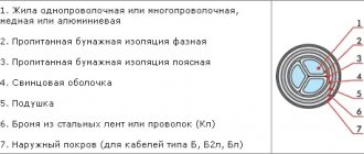
The main division of all types of optical cables occurs primarily from the conditions of their installation (Fig. 1). The main task is to protect the optical fiber from all external influences.
Rice. 1. Designs are OK
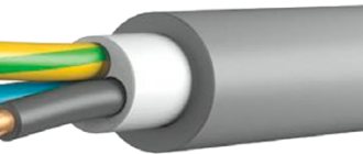
Optical cable for blowing into pipes
The method of installation in pipes is quite promising for reasons of convenience and practicality of the technology. The design of the cable is very simple (Fig. 2), glass fibers are applied to the core as additional strength elements, and an outer sheath is placed on top. The dense pipe protects the cable from possible mechanical damage. Recently, blowing microtubes into sewers has become a popular trend. A microcable has been developed for microtubes, where there is no additional protection other than the outer sheath. This option is smaller in size (by the way, in this option it is possible to use an optical fiber with a reduced diameter, 200-micron fiber SMF-28® Ultra 200, in order to also reduce the diameter of the modules in the optical fiber).
Rice. 2 OK for blowing into pipes
Subscribe to the VOLS.Expert channel
We show how to correctly install optical couplings and cross-connects, analyze common mistakes, and give useful advice to specialists.
YouTube
Optical cable for installation in cable ducts
When laying in cable ducts, there is a need to protect the cable from rodents. Therefore, the cable design provides armor in the form of corrugated steel tape, wire armor or glass fibers (Fig. 3). There are options both with and without an intermediate shell. It is possible to use two additional steel wires in the OK design, acting as a load-bearing element.
Rice. 3 OK for cable ducting
Optical cable for laying in the ground
The most severe option for laying a cable is directly into the ground without any additional protection (Fig. 4). Optical cables in their design have armor in the form of galvanized steel or rope wire, one or two layers, depending on the required characteristics. Provides protection from both transverse compression and tensile loads.
Rice. 4 OK for laying in the ground (wire armor)
When a cable with similar characteristics, but at the same time completely dielectric, is needed, armor made of fiberglass rods is used in the design instead of wire (Fig. 5).
Rice. 5 OK for laying in the ground (dielectric)
Advantages, types and types of optical fiber
The intensive growth in the use of fiber optic cables in the world has been going on for more than 40 years. This is due to the many advantages of fiber optics. The most important are: very high throughput of a single fiber, low signal attenuation even over very long distances, small size and light weight, complete immunity to radio interference and electromagnetic fields. Due to current environmental issues, an important feature of fibers is the absence of any environmental impact, which is very important when designing fiber optic lines. These connections are largely reliable, easy to use, provide workplace safety and significant efficiency, which is why they are becoming increasingly popular.
Types of wires with optical fibers in power lines
Fiber optic cables are produced in bundles containing from tens to several hundred fibers in one bundle. Fiber optic cables can be used in power lines as: phase conductors (live) or lightning conductors (grounding potential conductors) and self-supporting dielectric (additional cables in a line containing only fiber optic cables). There are several types of conductors associated with optical fibers. OPGW (Optical Ground Wire) are lightning rods commonly used in 110 kV overhead power lines.
From a design point of view, there are two types of wires:
- wires consisting of one central tube (made of aluminum or stainless steel) containing optical fibers and an outer layer of aluminum alloys,
- hoses with a stainless steel socket; they consist of several steel wires forming cores and an outer layer of aluminum alloys. Optical fibers are placed in a special stainless steel tube and form the core of the cable.
The most important advantages of these cables are the following:
- possibility of application in existing lines (instead of conventional steel and aluminum wires such as AFL), in most cases without the need to strengthen the column structure,
- easy installation, using existing cable,
- reliability and durability.
ADSS (All Dielectric Self Supporting) - fiber optic cables without metal elements. They are made from a centrally located rod-shaped FRP core surrounded by multiple tubes containing optical fibers. Between the inner and outer sheath of the cable are very strong aramid fibers, which give ADSS cables adequate mechanical strength.
ADSS cables have a slight increase in sag. When choosing an attachment point for ADSS cables, it is also necessary to take into account the distribution of the electric field strength between the phase wires, since in the event of rain or high air humidity, the outer sheath is exposed to micro-discharges. Placing wires in an area with too much electric field leads to rapid destruction of their sheath. The solution to this problem is the use of semiconductor cables, which, due to the high electromagnetic field strength, are usually used in lines with a voltage of no more than 110 kV. At higher voltages, special cables made of materials resistant to electric fields are used. When designing the suspension of ADSS cables on existing power lines, the additional stress placed on the supporting structures must be taken into account and appropriate reinforcements must be provided.
MASS (Metallic Aerial Self Supporting ) - self-supporting cables made of aluminum steel wire combined with optical fiber. They are very similar to OPGW cables, but do not provide a lightning conductor or electrical function in the line. For this reason, MASS cables typically hang slightly lower than the phase wires.
This solution is an alternative to the standard method of fastening fiber optic cables in high-voltage lines and is usually used when it is necessary to increase the number of fibers in the line, and replacing existing OPGW, OPPC or ADSS cables is either impossible or not economically feasible. Due to their high mechanical strength, low weight and diameter, these cables slightly increase the load on the pole structure.
Sky Wrap is a dielectric fiber optic cable wrapped around a traditional lightning conductor or phase power line. It is used in situations where the existing traditional fiber optic cable is in good condition and replacement with OPGW cable is not economically feasible, or where there is a need to increase the number of fibers in the installed OPGW cable. Sky Wrap is assembled using special robots with their own drive, moving along a cable and remotely controlled from the ground. The advantages of using these cables are: low additional load on the line (significantly less than, for example, ADSS cables), low sensitivity to vibrations (thanks to the voltage-controlled spiral winding), can also be installed on existing OPGW cables, simple and quick installation, low cost of the entire system compared to other solutions. Sky Wrap cables can also be used on 15kV lines and are then installed using a robot.
On video: Installation of sky Wrap cable
ADL (All Dielectric Lashed Cables) - dielectric fiber optic cables attached to the lightning rod using Kevlar tape. They differ from Sky Wrap in that they are attached to a support cable and are fixed from below. Installation is carried out using a special self-propelled robot.
Submarine optical cable
An underwater fiber optic cable (Fig. 6) is required for laying in offshore areas (coastal shelf and deep-sea), including in all types of soils, including rocky and subject to permafrost deformations, in swamps, at crossings of navigable rivers and other water barriers, in cable ducts, pipes, blocks, trays, tunnels, overpasses, bridges, collectors.
Rice. 6 Submarine optical cable
The design of such a cable has additional protection against water penetration in the form of an aluminum polymer tape.
Optical cable for suspension
The most common method of building fiber optic lines today. The cable must withstand tensile loads along its entire length. Optical cables for suspension are of the “8” type (Fig. 7) and round (Fig. 9).
Optical cables of type “8” have a metal (Fig. 7) or fiberglass cable (Fig. 8) in their design. The fiberglass cable is completely dielectric (Fig. 8).
Rice. 7 OK for suspension (with external power element, metal cable)
Telecom operators are gradually switching to round self-supporting optical cable (Fig. 9) due to some disadvantages of the “8” cable. You can read more about the shortcomings in the article about the basic principles of selecting trunk optical cables.
Rice. 8 OK for suspension (with external power element, fiberglass cable)
Suspended self-supporting cable or self-supporting non-metallic optical cable (OKSN). This cable is available in both aramid and glass fiber versions. Cables made with aramid threads are smaller in diameter and lighter compared to glass fibers. Also, aramid threads have a two-fold margin of tensile strength in relation to the maximum permissible loads. Self-supporting cable on aramid threads is certified for use at the facilities of JSC FGC UES of Russia and JSC IDGC Holding, but on glass threads it is prohibited.
Read more about the application and installation features of the OKSN cable.
Rice. 9. Suspended self-supporting OK
Optical fiber: types, applications, photographs
Theory
The most complete theory of signal transmission through optical waveguides is presented on the pages. • Theory of fiber optic transmission. Fundamental principles. • Refractive index • Snell's law. Internal and external reflection. • Structure of optical fiber • Nature of light transmission by glass
Types of optical fibers
Both ten years ago and at the end of 2013, optical fiber produced by industry was standardized and had many types and subtypes. The main types of optical fibers are discussed on the pages • Types and standards of optical fibers • Types of optical fibers
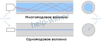
The most fundamental differences between multimode and single-mode
.
Multimode fiber
has a relatively large light-conducting core of 50 or 62.5 microns. The prefix “many” in this case is not synonymous with “good”, since it is precisely because of this multimode that the signal pulse shape is blurred. Such fibers are used for short networks (up to 1 km). The benefit of using them is the lower cost of receiving and transmitting equipment.
Multimode fibers are described in ITU-T G.651.1 and IEC 60793 standards.
The theory of transmission through them is discussed on the pages Mode propagation in fibers. Number of mod. Formula. Multimode fibers with step and smooth changes in refractive index
Single-mode fiber
used for communication over distances of tens and even hundreds of kilometers. Unlike a multimode, it has a thin light-conducting core of the order of 7 - 13 microns. Over the years of development of fiber optic technologies, several standards for such fibers have been developed and are in use.
Single-mode fibers are described in ITU-T standards G.652 • G.653 • G.654 • G.655 • G.656 • G.657
In appearance, optical fibers are no different. That is, without the appropriate devices, it is impossible to figure out which optical fiber has fallen into your hands. The appearance, color, and some properties of optical fibers are given by a special coating. Several sizes of OB have been standardized.
Optical fiber without varnish All photos Optical fiber (1 cell = 5mm)
125 µm
glass (quartz) part, which already contains a light-conducting core with a thickness depending on the standard. Photo of pieces of optical fiber remaining after the cleaver (Optical fiber cleavers)
250 µm
This is glass coated with varnish insulation. The varnish is usually used in different colors and, in addition to its insulating properties, the color of the fiber determines its conditional number in the module. (Color counting of fibers, identification by color in optical cables). The varnish coating provides additional resistance to bending. This fiber is similar to fishing line and can withstand bends with a radius of 5 mm (see photo)
900 µm
optical fiber in a buffer polymer coating. Used in the manufacture of cords and connecting fiber optic cross-connects. The color of the coating often determines the type of fiber. (Color counting in fiber optic cables)
Optical fiber with varnish (125 microns) and polymer (900 microns) coating, at the bottom the connector is closed with a cap (All photos)
Optical fiber preform
Production of optical fibers and cables
The bulk of optical fiber is produced by Fujikura (Japan) and Corning (USA). But more and more often, technological lines are appearing, including in Russia, producing one or another type of optical fiber. Some of the steps and principles of this process are described on the pages • Fiber Optic Manufacturing Technology. Manufacturing preforms for optical fiber • Drawing optical fiber from the preform
Next, the optical fiber is delivered on special drums to cable factories, where it is used in the production of optical cables. Since fiber optic cables differ in purpose and installation method, they accordingly have different amounts of armor coverings and differ in profile.
Optical cable marking
In the CIS countries there are many manufacturers of fiber optic cables, and at the same time, each enterprise develops its own technical specifications (TU) for its products and labels them in its own way. Marking systems are different and the following pages are devoted to the analysis of this problem • A guide to the marking and purpose of fiber optic cables • A list of possible markings of fiber optic cables in alphabetical order • Marking of fiber optic cables sorted by manufacturer
Laying fiber-optic communication lines (FOCL)
FOCLs are laid along overhead power lines, in the ground, cable ducts, along the walls of buildings and indoors. Official documents are devoted to the laying of fiber-optic cables along overhead power lines: • Rules for the design, construction and operation of fiber-optic communication lines on overhead power lines with a voltage of 0.4-35 kV • Rules for the design, construction and operation of fiber-optic communication lines on overhead power lines voltage 110 kV and above
The remaining types of laying are almost no different from the methods of laying cables with metal conductors and their features are described on the page from the “SLSMSS Manual”: Features of laying optical cables
Installation of fiber-optic line couplings and terminal devices
Enlarge photo
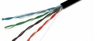
Fiber optic cables are similar in appearance to regular cables. The whole complexity of “optics” lies in the connection of optical fibers with each other. It will not be possible to connect them “on the knee”; any type of OV connection requires specialized tools and devices. Pages are devoted to methods of installation and measurements on optical fiber when installing couplings, cross-connects and connectors • FOCL terminal devices. Connectors • Fiber optic attenuators for fiber optic lines • Fiber optic cleaver. Gel connectors for fiber-optic lines • Splicing of fiber-optic lines. Types of welding machines • Description of installation of fiber optic couplings and optical cross connects
The following photo shows optical fibers laid in a fiber optic coupling cassette
Optical fiber in the coupling cassette (Enlarge photo)
Fiber measurements
Measurements of optical fibers are made before installation (control of cable reels), during the installation of fiber optic couplings and cross-connects, and during the fiber-optic communication line. Measurements are carried out by two types of instruments: measurements with fiber optic testers and optical reflectometers (OTDR). Pages are devoted to OF measurements • Types of fiber optic communication lines measurements. Fiber Optic Measurements • Fiber Optic Cable (FOC) measurements during installation
This topic is covered in even more detail on the pages of Lisven’s book Reflectometry of Optical Fibers. • Loss measurement using optical testers • Operating principle of OTDR • Purpose of OTDR
Aging of fiber optic (optical) cables
• Theory • Measuring the mechanical characteristics of fibers Tensile strength Static fatigue Fiber durability Brillouin reflectometry method + From correspondence → Large attenuation of G.652 at 1550 nm Premature aging of overhead optical cable + From practice → Cable design and fiber tension
Documentation for fiber-optic communication lines
Installation of fiber-optic couplings and cross-connects, as well as all measurements of optical cables must be documented in appropriate protocols and passports. The following are links to pages of official rules and guidelines for the construction of communication lines. • Protocol for measuring the attenuation of optical fibers of the building length, before laying (input control) • Protocol for measuring the attenuation of optical fibers of the laid building length, • Protocol for installing coupling No. “n” • Protocol for installing an optical cross-connect at the site • Protocol for measuring the attenuation of optical fibers of the installed cable line • Reflectograms of optical fibers No. 1...,p on the mounted line • Certificate for the mounted coupling OK. Protocol for input control of construction length is OK. List of grouping construction lengths OK at the site • Passport for fiber-optic lines for overhead lines with a voltage of 0.4-35 kV (FOCL-VL 0.4-35 kV) • Passport for the regeneration section of FOCL-VL 0.4-35 kV. Protocol for measuring the attenuation of a fiber-optic communication line (FOCL-VL 0.4-35 kV) and in coupling splices
Coupling installation instructions:
• Shortened fiber optic coupling MOGU • Dead end fiber optic coupling MTOC
Answers on the topic “Optical fiber or fiber optic communication line”
Answers to questions on the topic “Optical fiber or FOCL” from the site’s correspondence are posted on the following pages • Consequences of stretching a fiber optic cable (FOCL) • Wavelength multiplexing in single-mode fiber. Wave and mode • OB amplifiers EDFA. Inaccuracy in the directory OK. Double-sided reflectograms • Features of optical reflectometers. Reflectogram of a fiber-optic line • Norms of losses at the junction when measuring optical cables • Line at the junction of the optical fiber: reliability and losses. Different optical lengths OK • OTDR measurement of short OB lines. Minimum distance between couplings • Is the linear attenuation between fiber-optic line couplings important • How many tractors are there when laying a fiber-optic cable • Assessment of the degree of damage to the fiber-optic cable sheath • The use of protectors during the construction of fiber-optic lines on overhead line supports • Reading traffic from the fiber without breaking the instrumentation on the fiber. Lightning protection OK. Armor jumper for fiber-optic lines
Plastic optical fiber
Plastic optical fibers are increasingly used in industry and everyday life. The large linear attenuation of the signal in them also determines the limit of their use. All of them are used in local systems of short length. As a rule, these are either lighting installations or for connecting sensors with automation systems, including automotive ones. About similar use on the page Other types of optical fibers and Sensors using optical fiber
The use of plastic optical fiber is constantly expanding, but there are no plans to use them in long-distance communication lines in the near future.
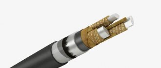
Optical cable built into lightning protection cable (OPGT)
This is a separate category of optical cables that are used on overhead power lines with voltages of 35 kV and higher (Fig. 12). The OPGT structures are completely metal.
Rice. 12 Lightning wire/OCGT
Depending on the required technical characteristics, OPGW can be of different designs in the core design:
- OKGT-Ts - optical cable built into a lightning protection cable with a central module;
- OKGT-TS-A - optical cable built into a lightning protection cable with a central module clad in aluminum;
- OKGT-S is an optical cable built into a lightning protection cable with an optical module in a layer.
If we use an OKFP (optical cable built into a phase wire), we get a “two in one” product: transmission of electrical energy and a fiber-optic communication cable line. Read more about OKFP in our article.
Using OPGT and OKFP designs, it is possible to monitor power lines.
Where a communication line has already been laid and protection against lightning strikes is required, GTK is used - a corrosion-resistant lightning protection cable.
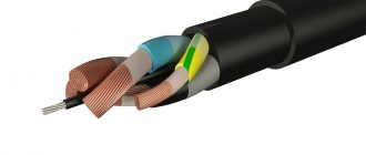
FOC design
Cable designs vary depending on the application. The requirements for an underground cable are much higher than for a line inside a building. The differences are caused by the need to ensure the required cable strength and sufficient insulation from external influences in different conditions.
The design of the light guide is the same in all cases. This is a thread made of ultra-pure quartz glass or plastic.
When high tensile strength is required, a core of flexible metal or durable plastic is laid in the center of the cable, around which optical modules with three layers of insulation are located.