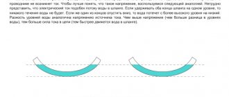
To maintain an electric current in a conductor for a long time, it is necessary that the charges delivered by the current are constantly removed from the end of the conductor, which has a lower potential (consider that current carriers are assumed to be positive charges), while charges are constantly supplied to the end with a higher potential. That is, it is necessary to ensure the circulation of charges. In this cycle, charges must move along a closed path. The movement of current carriers is realized using forces of non-electrostatic origin. Such forces are called third parties. It turns out that to maintain the current, external forces are needed that act along the entire length of the circuit or in individual sections of the circuit.
What is EMF: explanation in simple words
EMF is understood as the specific work of external forces to move a single charge in the circuit of an electrical circuit. This concept in electricity involves many physical interpretations related to various areas of technical knowledge. In electrical engineering, this is the specific work of external forces that appears in inductive windings when an alternating field is induced in them. In chemistry, it means the potential difference that occurs during electrolysis, as well as during reactions accompanied by the separation of electrical charges.
What is a photoresistor?
Read more
Marking of SMD transistors.
Read more
How to make a motion sensor with your own hands.
Read more
In physics, it corresponds to the electromotive force created at the ends of an electrical thermocouple, for example. To explain the essence of EMF in simple words, you will need to consider each of the options for its interpretation. Before moving on to the main part of the article, we note that EMF and voltage are very similar concepts in meaning, but they are still somewhat different. In short, the EMF is on the power source without a load, and when a load is connected to it, it is already a voltage. Because the number of volts on the power supply under load is almost always slightly less than without it. This is due to the internal resistance of power sources such as transformers and galvanic cells.
Additional material on the topic: In simple words about voltage converters.
Electromotive force (emf), a physical quantity characterizing the action of third-party (non-potential) forces in direct or alternating current sources; in a closed conducting circuit is equal to the work of these forces to move a single positive charge along the circuit. If we denote the field strength of external forces by Etr, then the emf in a closed loop (L) is equal to , where dl is the element of the loop length. The potential forces of an electrostatic (or stationary) field cannot maintain a constant current in the circuit, since the work of these forces on a closed path is zero. The passage of current through the conductors is accompanied by the release of energy - heating of the conductors.
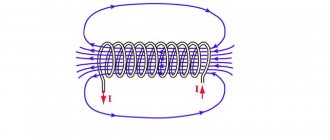
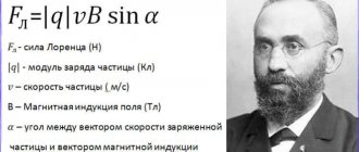
Third-party forces set in motion charged particles inside current sources: generators, galvanic cells, batteries, etc. The origin of third-party forces can be different. In generators, external forces are forces from the vortex electric field that arises when the magnetic field changes over time, or the Lorentz force acting from the magnetic field on electrons in a moving conductor; in galvanic cells and batteries - these are chemical forces, etc. Emf determines the current strength in the circuit at a given resistance (see Ohm's law). EMF, like voltage, is measured in volts.
What is EMF.
Electrical circuit efficiency
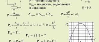
It's not hard to see why a resistor is called a payload. Imagine it's a light bulb. The heat generated by a light bulb is beneficial
, since thanks to this warmth the light bulb fulfills its purpose - giving light.
Let us denote the amount of heat released by the payload during time .
If the current in the circuit is equal to , then
A certain amount of heat is also released at the current source:
The total amount of heat released in the circuit is equal to:
Electrical circuit efficiency
is the ratio of useful heat to total heat:
The efficiency of the circuit is equal to unity only if the current source is ideal.
Nature of EMF
The reason for the occurrence of EMF in different current sources is different. Based on the nature of occurrence, the following types are distinguished:
- Chemical emf. Occurs in batteries and accumulators due to chemical reactions.
- Thermo EMF. Occurs when contacts of dissimilar conductors located at different temperatures are connected.
- Induction emf. Occurs in a generator when a rotating conductor is placed in a magnetic field. An emf will be induced in a conductor when the conductor crosses the lines of force of a constant magnetic field or when the magnetic field changes in magnitude.
- Photoelectric emf. The occurrence of this EMF is facilitated by the phenomenon of external or internal photoelectric effect.
- Piezoelectric emf. EMF occurs when substances are stretched or compressed.
It will be interesting➡ Phantom power for a microphone: connection diagram
Electromagnetic induction (self-induction)
Let's start with electromagnetic induction. This phenomenon is described by Faraday's law of electromagnetic induction. The physical meaning of this phenomenon is the ability of an electromagnetic field to induce an emf in a nearby conductor. In this case, either the field must change, for example, in the magnitude and direction of the vectors, or move relative to the conductor, or the conductor must move relative to this field. In this case, a potential difference arises at the ends of the conductor.
Experience demonstrates the appearance of EMF in a coil when exposed to a changing magnetic field of a permanent magnet. There is another phenomenon that is similar in meaning - mutual induction. It lies in the fact that a change in the direction and current strength of one coil induces an EMF at the terminals of a nearby coil; it is widely used in various fields of technology, including electrical and electronics. It underlies the operation of transformers, where the magnetic flux of one winding induces current and voltage in the second.
What is self-induction.
In electrical engineering, a physical effect called EMF is used in the manufacture of special AC converters that provide the required values of effective quantities (current and voltage). Thanks to the phenomena of induction and self-induction, engineers have been able to develop many electrical devices: from a conventional inductor (inductor) to a transformer. The concept of mutual induction refers only to alternating current, the flow of which in a circuit or conductor changes the magnetic flux.
Table of parameters of electromotive force of induction.
From electrostatics to electrokinetics
Between the end of the 18th and the beginning of the 19th century, the work of scientists such as Coulomb, Lagrange and Poisson laid the mathematical foundations for the determination of electrostatic quantities. Progress in the understanding of electricity at this historical stage is obvious. Franklin had already introduced the concept of “amount of electrical substance,” but so far neither he nor his successors have been able to measure it.
Following Galvani's experiments, Volta tried to find evidence that the animal's "galvanic fluids" were of the same nature as static electricity. In his search for truth, he discovered that when two electrodes of different metals come into contact through an electrolyte, both become charged and remain charged despite the circuit being closed by the load. This phenomenon did not correspond to existing ideas about electricity because electrostatic charges in such a case had to recombine.
Volta introduced a new definition of the force acting in the direction of separating charges and maintaining them in this state. He called it electromotive. Such an explanation for the description of battery operation did not fit into the theoretical foundations of physics at that time. In the Coulomb paradigm of the first third of the 19th century. d.s. Volta was determined by the ability of some bodies to generate electricity in others.
Ohm made the most important contribution to the explanation of the operation of electrical circuits. The results of a series of experiments led him to the construction of the theory of electrical conductivity. He introduced the quantity “voltage” and defined it as the potential difference across the contacts. Like Fourier, who in his theory distinguished between the amount of heat and temperature in heat transfer, Ohm created a model by analogy relating the amount of charge transferred, voltage and electrical conductivity. Ohm's law did not contradict the accumulated knowledge of electrostatic electricity.
You might be interested in this Symbol of radio components on the diagram and their name
Then, thanks to Maxwell and Faraday, explanatory models of current received a new field theory. This allowed the development of a field-related energy concept for both static potentials and electromotive force. The main dates for the evolution of the concept of EMF:
- 1800 - creation of the Voltaic galvanic battery;
- 1826 - Ohm formulates his law for a complete chain;
- 1831 - discovery of electromagnetic induction by Faraday.
EMF in everyday life and units of measurement
Other examples are found in the practical life of any ordinary person. This category includes such familiar things as small batteries, as well as other miniature batteries. In this case, the working EMF is formed due to chemical processes occurring inside constant voltage sources. When it occurs at the terminals (poles) of the battery due to internal changes, the element is completely ready for operation. Over time, the EMF decreases slightly, and the internal resistance increases noticeably.
As a result, if you measure the voltage on a AA battery that is not connected to anything, you see the normal 1.5V (or so), but when a load is connected to the battery, let’s say you installed it in some device, it does not work. Why? Because if we assume that the voltmeter’s internal resistance is many times higher than the internal resistance of the battery, then you measured its EMF. When the battery began to supply current to the load at its terminals, it became not 1.5V, but, say, 1.2V - the device did not have enough voltage or current for normal operation.
Calculation of EMF.
It was precisely these 0.3 V that dropped on the internal resistance of the galvanic element. If the battery is very old and its electrodes are destroyed, then there may be no electromotive force or voltage at all at the battery terminals - i.e. zero. A very small electromotive force is induced within the receiver antenna, which is then amplified by special cascades, and we receive our television, radio and even Wi-Fi signal.
Material on the topic: Selecting a digital-to-analog converter.
Current measurement
You can measure the current directly with an ammeter connected to the open circuit of the measured circuit (Fig. 3, a).
Rice. 3. Current measurement circuits
If it is necessary to expand the measurement limits of the ammeter, it is necessary to connect a resistor in parallel with the ammeter (Fig. 3, b), which is most often called a shunt . Then only part of the current will pass through the ammeter, and the rest through the shunt. Since the resistance of ammeters is usually small, to significantly expand the measurement limits, the shunt resistance must be very small. There are formulas for calculating the shunt resistance, but usually in practice you have to manually adjust its resistance by monitoring the current with a reference ammeter.
To measure large alternating currents, measuring current transformers are often used (Fig. 3, c). Their primary winding, included in the break of the measured circuit, has a number of turns W1 less than the number of turns W2 of the secondary winding, i.e. the transformer is step-up in voltage, but it is step-down in current. The ammeter is connected to the output of the secondary winding of the current transformer. Often laboratory current transformers do not have a pre-made primary winding at all, and their housing has a wide through hole through which the experimenter himself winds the required number of turns (Fig. 3, d). Knowing the number of turns of the secondary winding (it is usually indicated on the body of the current transformer), you can select the transformation ratio n = W1/W2 and determine the measured current Ix from the readings of the ammeter Ipr using the following formula:
Iх = Ipr/n
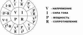
A completely different way is used to measure currents in electronic circuits, which are usually soldered and manufactured on printed circuit boards; It is almost impossible to make any rupture in them. To measure currents in these cases, voltmeters are used (usually electronic ones with high internal resistance to eliminate the influence of the device on the operation of the electronic circuit), connecting them to circuit resistors, the values of which are either known or can be pre-measured. Using Ohm's law, you can determine the current strength:
I = U/R
How is EMF formed?
The ideal source of EMF is a generator whose internal resistance is zero and the voltage at its terminals does not depend on the load. The power of an ideal EMF source is infinite. A real EMF source, unlike an ideal one, contains an internal resistance Ri and its voltage depends on the load (Fig. 1, b), and the power of the source is finite. The electrical circuit of a real EMF generator is a series connection of an ideal EMF generator E and its internal resistance Ri.
It will be interesting➡ Direct current - definition and parameters
In practice, in order to bring the operating mode of a real EMF generator closer to the operating mode of an ideal one, they try to make the internal resistance of the real generator Ri as small as possible, and the load resistance Rн must be connected with a value no less than 10 times greater than the internal resistance of the generator, i.e. it is necessary to fulfill the condition: Rн >> Ri
To ensure that the output voltage of a real EMF generator does not depend on the load, it is stabilized using special electronic voltage stabilization circuits. Since the internal resistance of a real EMF generator cannot be made infinitely small, it is minimized and made standard for the possibility of coordinated connection of energy consumers to it. In radio engineering, the standard output resistance of EMF generators is 50 Ohms (industrial standard) and 75 Ohms (household standard).
For example, all television receivers have an input impedance of 75 Ohms and are connected to the antennas with a coaxial cable of exactly this impedance. To get closer to ideal EMF generators, supply voltage sources used in all industrial and household electronic equipment are made using special electronic output voltage stabilization circuits, which make it possible to maintain an almost constant output voltage of the power source in a given range of currents consumed from the EMF source (sometimes its called a voltage source).
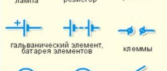
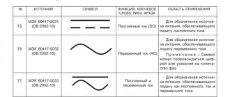
On electrical diagrams, EMF sources are depicted as follows: E - source of constant EMF, e(t) - source of harmonic (variable) EMF in the form of a function of time. The electromotive force E of a battery of identical elements connected in series is equal to the electromotive force of one element E multiplied by the number n of elements of the battery: E = nE.
Direct current and EMF.
Measuring inductances
Measuring inductances is somewhat more complicated. This is due to the fact that any coil (winding of a transformer, etc.) has, in addition to inductance, also resistive resistance. Therefore, in many cases, the impedance of the inductor is first measured:
It can be determined by the ammeter and voltmeter method by measuring voltage and current with measuring instruments of an alternating voltage circuit (Fig. 7, a) z = U/I. When a constant voltage is applied to the circuit (Fig. 7, b), as discussed above, the resistive resistance of the coil R can be determined.
Rice. 7. Inductance measurement circuits
Then
In turn, inductive reactance
With a known value of frequency / supply voltage, it is easy to find the value of the desired inductance value
For small inductance values (for example, loop coils of radio-electronic devices), you can use a resonant circuit, similar to the circuit for determining capacitance by the resonant method.
To measure inductance, you can also use alternating current bridges and special measuring instruments—kumeters—that allow you to determine not only the inductance value, but also such a characteristic as the quality factor of the coil, which characterizes the quality of the coil’s operation in electronic circuits.
Electromotive force (EMF) of the energy source
To maintain an electric current in a conductor, an external energy source is required, which constantly creates a potential difference between the ends of this conductor. Such energy sources are called electrical energy sources (or current sources). Sources of electrical energy have a certain electromotive force (abbreviated EMF), which creates and maintains a potential difference between the ends of the conductor for a long time.
Expert commentary
Lagutin Vitaly Sergeevich
Engineer with a degree in Computer Software and Automated Systems, MEPhI, 2005–2010.
Ask a Question
It is sometimes said that emf creates an electric current in a circuit. We must remember that this definition is conventional, since we have already established above that the reason for the emergence and existence of electric current is the electric field.
A source of electrical energy produces a certain amount of work by moving electrical charges throughout a closed circuit. The unit of measurement of electromotive force is the volt (abbreviated volt is denoted by the letter B or V - “ve” in Latin). The emf of a source of electrical energy is equal to one volt if, when moving one coulomb of electricity throughout a closed circuit, the source of electrical energy does work equal to one joule:
Electromotive force (EMF) of an energy source.
In practice, both larger and smaller units are used to measure EMF, namely:
- 1 kilovolt (kV, kV), equal to 1000 V;
- 1 millivolt (mV, mV), equal to one thousandth of a volt (10-3 V),
- 1 microvolt (μV, μV), equal to one millionth of a volt (10-6 V).
Obviously, 1 kV = 1000 V; 1 V = 1000 mV = 1,000,000 μV; 1 mV = 1000 µV.
Currently, there are several types of electrical energy sources. For the first time, a galvanic battery was used as a source of electrical energy, consisting of several zinc and copper circles, between which skin soaked in acidified water was laid. In a galvanic battery, chemical energy was converted into electrical energy (this will be discussed in more detail in Chapter XVI). The galvanic battery got its name from the Italian physiologist Luigi Galvani (1737-1798), one of the founders of the doctrine of electricity.
Numerous experiments on the improvement and practical use of galvanic batteries were carried out by the Russian scientist Vasily Vladimirovich Petrov. At the beginning of the last century, he created the world's largest galvanic battery and used it for a number of brilliant experiments. Sources of electrical energy that work on the principle of converting chemical energy into electrical energy are called chemical sources of electrical energy.
Good to know: How to calculate the power of an electric current.
Another main source of electrical energy, widely used in electrical and radio engineering, is the generator. In generators, mechanical energy is converted into electrical energy. In chemical sources of electrical energy and in generators, the electromotive force manifests itself in the same way, creating a potential difference at the source terminals and maintaining it for a long time.
These terminals are called the poles of the electrical energy source. One pole of an electrical energy source has a positive potential (lack of electrons), is indicated by a plus sign (+) and is called the positive pole.
The other pole has a negative potential (excess electrons), is indicated by a minus sign (—) and is called the negative pole. From sources of electrical energy, electrical energy is transmitted through wires to its consumers (electric lamps, electric motors, electric arcs, electric heating devices, etc.).
It will be interesting➡ What is an electric field: an explanation in simple words
Examples of problem solving
For each position in the first column, select the corresponding position in the second:
| PHYSICAL QUANTITIES | FORMULAS |
| Electromotive force | |
| Current strength | |
| Resistance | |
| Potential difference |
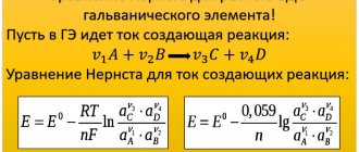
Solution: The electromotive force of a galvanic cell is a quantity numerically equal to the work of external forces when moving a single positive charge inside the element from one pole to the other.
The work of external forces cannot be expressed through a potential difference, since external forces are non-potential and their work depends on the shape of the trajectory of the charges.
EMF is determined by the formula:
The current strength is determined by the formula:
Resistance is determined by the formula:
The potential difference is determined by the formula:
Correct answer:
| PHYSICAL QUANTITIES | FORMULAS |
| Electromotive force | |
| Current strength | |
| Resistance | |
| Potential difference |
FAQ
What is electromotive force?
This is the ratio of the work of external forces when moving a charge along a closed circuit to the absolute value of this charge.
What is an electrical circuit?
A set of devices that are connected by conductors, designed to allow current to flow.
What does Ohm's law sound like for a complete circuit?
The current strength in a complete circuit is equal to the ratio of the circuit's emf to its total resistance.
Lenz's rule
We will call the magnetic flux, a change in which leads to the appearance of an induction current in the circuit, external magnetic flux
.
And we will call the magnetic field itself, which this magnetic flux creates, external magnetic field
.
Why do we need these terms? The fact is that the induction current arising in the circuit creates its own
a magnetic field that, according to the principle of superposition, is added to an external magnetic field.
Accordingly, along with the external magnetic flux, its own
magnetic flux created by the magnetic field of an induction current.
It turns out that these two magnetic fluxes - internal and external - are interconnected in a strictly defined way.
Lenz's rule
.
The induced current always has a direction such that its own magnetic flux prevents a change in the external magnetic flux
.
Lenz's rule allows you to find the direction of the induced current in any situation.
Let's look at some examples of applying Lenz's rule.
Let us assume that the circuit is penetrated by a magnetic field, which increases with time (Fig. (3)). For example, we bring a magnet closer to the contour from below, the north pole of which in this case is directed upward, towards the contour.
The magnetic flux through the circuit increases. The induced current will be in such a direction that the magnetic flux it creates prevents the increase in external magnetic flux. To do this, the magnetic field created by the induction current must be directed against
external magnetic field.
The induced current flows counterclockwise when viewed from the direction of the magnetic field it creates. In this case, the current will be directed clockwise when viewed from above, from the side of the external magnetic field, as shown in (Fig. (3)).
Rice. 3. Magnetic flux increases
Now suppose that the magnetic field penetrating the circuit decreases with time (Fig. 4). For example, we move the magnet downward from the loop, and the north pole of the magnet points toward the loop.
Rice. 4. Magnetic flux decreases
The magnetic flux through the circuit decreases. The induced current will have a direction such that its own magnetic flux supports the external magnetic flux, preventing it from decreasing. To do this, the magnetic field of the induction current must be directed in the same direction
, as the external magnetic field.
In this case, the induced current will flow counterclockwise when viewed from above, from the side of both magnetic fields.
Faraday's Law + Lenz's Rule = Module Removal
Above we promised to remove the module in Faraday’s law (5). Lenz's rule allows us to do this. But first we will need to agree on the sign of the induced emf - after all, without the module on the right side of (5), the magnitude of the emf can be either positive or negative.
First of all, one of two possible directions for traversing the contour is fixed. This direction is declared positive
.
The opposite direction of traversing the contour is called negative
. Which direction of traversal we take as positive does not matter - it is only important to make this choice.
Magnetic flux through a loop is considered positive if the magnetic field penetrating the loop is directed in the direction from which the circuit is traversed in the positive direction counterclockwise. If, from the end of the magnetic induction vector, the positive direction of the round is seen clockwise, then the magnetic flux is considered negative.
Induction emf is considered positive if the induced current flows in a positive direction. In this case, the direction of external forces arising in the circuit when the magnetic flux through it changes coincides with the positive direction of bypassing the circuit.
On the contrary, induced emf is considered negative if the induced current flows in a negative direction. In this case, external forces will also act along the negative direction of the circuit bypass.
So, let the circuit be in a magnetic field. We fix the direction of the positive circuit bypass. Let's assume that the magnetic field is directed there, looking from where the positive detour is made counterclockwise. Then the magnetic flux is positive: .
Let us further assume that the magnetic flux increases. According to Lenz's rule, the induced current will flow in the negative direction (Fig. 5).
Rice. 5. Magnetic flux increases
Therefore, in this case we have . The sign of the induced emf turned out to be opposite to the sign of the rate of change of the magnetic flux. Let's check this in another situation.
Namely, let us now assume that the magnetic flux decreases. According to Lenz's rule, the induced current will flow in the positive direction. Therefore, (Fig. 6).
Rice. 6. Magnetic flux increases
This is, in fact, a general fact: given our agreement on the signs, Lenz’s rule always leads to the fact that the sign of the induced emf is opposite to the sign of the rate of change of the magnetic flux
:
(6)
Thus, the modulus sign in Faraday’s law of electromagnetic induction is eliminated.