Design and principle of operation
All starters used for fluorescent lamps have a similar device, which looks like this:
- The device itself is a small-sized gas-discharge lamp that uses the glow discharge principle during operation.
- The flask is most often made of glass and contains an inert gas inside. In modern versions it can be neon or a mixture of hydrogen and helium.
- The flask is placed in a housing that performs protective functions; it is made of metal or durable types of plastic.
- The top cover of the housing can be equipped with an inspection window, if the design provides for its presence.
- The starter is equipped with two electrodes , which are made of bimetal; their design may differ for different models.
- Additionally, the design always contains a capacitor , which is capable of not only smoothing the closing moment and opening the contacts of the device, but also extinguishing the arc that forms between the contacts at the same time. Without a capacitor, there is a risk of welding the electrodes with an arc, which significantly reduces the service life of the starter.
The operating principle of such a device is as follows:
- Initially, both electrodes included in the starter design are in the open position.
- After connecting to the power supply network, a glow discharge occurs inside the device, the current value of which varies from 20 to 50 mA.
- The resulting discharge affects the bimetal electrodes, gradually heating them.
- The heating material provokes bending of the starter electrodes, which helps to stop the discharge and subsequent closure of the electrical circuit.
- Electric current begins to move through a closed circuit, it helps to heat the inductor and cathodes of the fluorescent lamp.
- Due to the disappearance of the glow discharge , the bimetallic electrodes begin to gradually cool down after a certain time. As a result of these changes, their extension occurs, which provokes chain rupture.
- The perfect action contributes to the generation of a pulse with a high voltage value, which acts on the throttle.
- The choke has a significant degree of inductance , so such an effect contributes to the ignition of the lamp.
- The glow of the lamp gradually increases and at the same time it begins to take large amounts of voltage from the electrical network. The starter has a connection parallel to the lamp, so it begins to lack power so that it can create a new glow discharge. Thanks to this, the electrodes subsequently remain in an open state.
How does it work
When voltage is applied to the circuit where the starter is installed, it reaches its electrodes, between which a glow discharge appears. The discharge current is insignificant, ranging from 20 to 50 mA. It is this discharge that begins to heat the electrodes, which bend under the influence of heat and after some time come into contact with each other. That is, the electrical circuit is closed, and the current is supplied further to the inductor, capacitor and fluorescent lamps. In this case, the glow discharge stops.
Please note that the starter switching voltage should be slightly less than the nominal network voltage, that is, 220 volts, but it should be greater than the switching voltage of the fluorescent lamps themselves.
So, the electrodes have touched each other, what next? Since there is no glow discharge between them, there is therefore no temperature that heats them. They cool down, which will ultimately lead to the opening of the electrodes and the circuit. It is at this moment that the so-called high-magnitude pulse voltage appears inside the inductor. It is from this that the fluorescent lighting device is ignited. During the operation of the fluorescent lamp itself, the current in the chain has a value equal to the current strength of the light source. The voltage drop, and therefore the current, is divided between the lighting device itself and the choke into equal parts.
Ignition
How does the starter ignite for a lamp? It should be noted that ignition efficiency is affected by two positions:
- the magnitude of the current at the cathodes of the lamp at the moment the electrodes open;
- duration of cathode heating.
The electromagnetic force inside the inductor depends on the current flowing through it. It is clear that insufficient current will not cause the luminescent device to ignite. And the current strength directly depends on the voltage in the circuit. And if the latter indicator is below the nominal value, then there is a high probability that the lamp will not light up immediately. Therefore, the starter will automatically try to do the same operation again and again until it lights up. The standard attempt frequency is 10 seconds.
If the voltage in the supply network drops below 80% of the nominal voltage, then this is not enough for the electrodes to heat up to the required temperature. That is, with such a fall, the lighting device simply does not light up.
Capacitor
The capacitor in the ballast system is installed in parallel with the starter. These two devices are interconnected. The main purpose of the capacitor:
- reduction of interference during the closing and opening of the starter electrodes;
- increasing the duration of the pulse when the electrodes are opened;
- prevention of electrode soldering due to high pulse voltage.
Most often, capacitors with a capacity of 0.003-0.1 μF are used in ballasts.
How long does it work
As the starter operates, the voltage that creates the glow discharge decreases. This can lead to the opposite effect when, when the fluorescent lamp is running, the starter electrodes suddenly begin to close spontaneously, which will lead to the extinguishing of the lamp itself. The electrodes will immediately open and, accordingly, the lamp will be ignited. Both processes are instantaneous, which leads to the flashing of the lamp. This not only affects the efficiency of its operation, but also reduces the life of the throttle, because during such operation it will simply overheat.
Therefore, the advice is to periodically check the starter and, if necessary, replace it with a new one. As soon as you see that the lamp is blinking, do not put off replacing it.
Connecting fluorescent lamps via starter
Connecting lamps with a choke or ballast initially assumes the presence of a starter in the circuit. A similar example will be considered below; a lamp with a power of 36-40W, a choke with the same characteristics and a starter with a power rating of 4-65W were used for it.
The connection itself looks like this:
- The design of the lamp has output contacts, which are the leads of the bulb's filament; they look like small protruding pins. They require parallel connection of the starter.
- During this process, one contact must be activated on each side of the lamp.
- After this, free contacts remain, which are necessary to connect the inductor through them. It must also be connected in parallel to the mains.
- The last capacitor to be connected in this circuit is connected in parallel with the lamp power contacts. The presence of this element is necessary to eliminate interference occurring in the network, as well as to perform reactive power compensation.
There are 2 connection methods, which are fundamentally different from each other, they depend on the number of lamps:
- A circuit with one lamp involves connecting the inductor and the lighting source itself in series to the power supply; the starter is installed in parallel with the lamp. A capacitor can be installed at the lamp input terminals, which, during the operation of the circuit, will be responsible for improving the parameters of the electric current.
- When implementing a circuit with several lamps, you will need to connect all the lamps and the inductor in series to the power supply. After this, starters are connected in parallel to each of the lamps. An important condition: the total power of these devices must be equal to the power indicator that the throttle itself has.
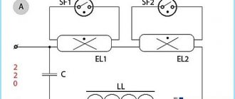
Connection diagram
The power of the light source must correlate with the parameters of the other components. If they do not match, then it is possible that either the circuit will not start at all, or the electrodes will be destroyed due to overheating when the startup starts.
To connect two LLs, circuit duplication is not required. It is advisable to reduce the number of elements. In this case, one of the chokes is released.
In the second diagram, additional gas-discharge lamps are connected in series, and the starters are connected in parallel. Otherwise the schemes are identical. The difference will be in the throttle rating. It must be designed for the total power of the lamps. The starter must match the lamp power. Typically, in a circuit with two lamps, the same power is used. A capacitor is desirable in parallel with the AC source. It is designed to improve nutritional parameters. With lamp powers of about 40 watts, a capacitance of 2 to 10 μF is usually sufficient. The capacitor voltage is selected not lower than twice the supply voltage.
Types of starters for fluorescent lamps
Several different types of starters have been developed, but only one type has become widespread, the operating principle of which is based on a glow discharge.
Such devices have several different classifications, one of the main ones divides them according to the structural features of the electrodes:
- In the asymmetrical variety, one of the electrodes always remains in a fixed and motionless state. In this case, the second electrode can always move and several different metals are necessarily used as the material for its manufacture.
- A symmetrical variety in which both electrodes are of bimetallic origin. This type of starter is used much more often today, since it is much more profitable than its asymmetrical counterpart.
Also, in other cases, the classification of starters can be carried out depending on the following factors:
- The power of the lamps that the device must light, usually this parameter varies from 4-22V to 80-140V.
- Leading manufacturers engaged in the production of starters for lamps. Today, the leaders are Phillips, Narva, Osram and General Electric.
- Popular models taking into account their features.
Execution options
There is a wide variety of electroluminescent lamps, but they can all differ in:
- form of execution;
- type of ballast;
- internal pressure.
The design can be the same as that of conventional fluorescent lamps - a linear tube or a tube in the shape of the Latin letter U. Compact options have been added to them, made to fit a familiar base using various spiral bulbs.
Ballast is a device that stabilizes the operation of the product. Electronic and electromagnetic types are the most common connection schemes.
Internal pressure determines the area of use of the products. Low-pressure lamps or energy-saving samples have been used for domestic purposes or public places. In industrial premises or places with reduced requirements for color rendering, high-pressure units are used.
To assess the ability of lighting, an indicator of the lamp power and its light output is used. Many more different classification parameters and design options can be given, but their number is constantly increasing.
Operating principle
The action of the starter is inextricably linked with the operation of the entire fluorescent lamp and occurs in the following order:
- Before starting work, the electrodes are open.
- After applying voltage from the network, a glow discharge occurs inside the flask with current parameters of 20-50 mA.
- The discharge begins to act on the bimetallic electrodes, gradually heating them up.
- Under the influence of heating, the electrodes bend, after which the glow discharge stops and the electrical circuit inside the lamp is closed.
- An electric current begins to flow through a closed circuit, heating the inductor and the cathodes of the lamp itself.
- After the glow discharge ceases, gradual cooling of the bimetallic electrodes begins. As a result, they open, unbend and the chain breaks.
- All previous actions led to the appearance of a high pulse voltage acting on the inductor. The inductor itself has inductance, under the influence of which the lamp begins to light.
- Gradually the lamp glow increases and reaches normal. Since the starter is connected in parallel with the lamp, it no longer has enough voltage to create a new glow discharge, since all the current is spent on maintaining the glow. Therefore, the electrodes remain open, but the lamp still continues to work.
Why do you need a starter and a choke in circuits for switching on fluorescent lamps?
The main elements of the circuit for switching on a fluorescent lamp with an electromagnetic ballast are a choke and a starter. The starter is a miniature neon lamp, one or both electrodes of which are made of bimetal. When a glow discharge occurs inside the starter, the bimetallic electrode heats up and then bends and short-circuits with the second electrode.
After voltage is applied to the circuit, current does not flow through the fluorescent lamp, since the gas gap inside the lamp is an insulator, and to break it down a voltage greater than the voltage of the supply network is required. Therefore, only the starter lamp lights up, the ignition voltage of which is lower than the mains voltage. A current of 20 - 50 mA flows through the inductor, the electrodes of the fluorescent lamp, and the neon lamp of the starter.
The starter consists of a glass cylinder filled with inert gas. Metal fixed and bimetallic electrodes are soldered into the cylinder, having leads passing through the bases. The cylinder is enclosed in a metal or plastic case with a hole in the upper part.
Diagram of the glow discharge starter device: 1 - leads, 2 - metal movable electrode, 3 - glass cylinder, 4 - bimetallic electrode, 6 - base
Starters for connecting fluorescent lamps to the network are available for voltages of 110 and 220 V.
Under the influence of current, the starter electrodes heat up and close. After closing, a current flows through the circuit that is 1.5 times the rated current of the lamp. The magnitude of this current is limited mainly by the resistance of the choke, since the starter electrodes are closed, and the lamp electrodes have little resistance.
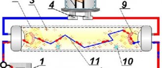
Elements of the circuit with a choke and starter: 1 – mains voltage terminals; 2 – throttle; 3, 5 – lamp cathodes, 4 – tube, 6, 7 – starter electrodes, 8 – starter.
In 1–2 s, the lamp electrodes heat up to 800–900 °C, as a result of which electron emission increases and breakdown of the gas gap is facilitated. The starter electrodes cool down, since there is no discharge in it.
When the starter cools, the electrodes return to their original state and break the circuit. At the moment the starter circuit breaks, an e.m. occurs. d.s. self-inductance in the inductor, the value of which is proportional to the inductance of the inductor and the rate of change of current at the moment the circuit breaks. Formed due to e. d.s. self-induction, an increased voltage (700 - 1000 V) is pulsed applied to a lamp prepared for ignition (the electrodes are heated). A breakdown occurs and the lamp begins to glow.
Approximately half the mains voltage is applied to the starter, which is connected in parallel with the lamp. This value is not enough to break down the neon light bulb, so it no longer lights up. The entire ignition period lasts less than 10 s.
Consideration of the lamp ignition process allows us to clarify the purpose of the main elements of the circuit.
The starter performs two important functions:
1) short-circuits the circuit in order to heat the lamp electrodes with increased current and facilitate ignition,
2) after heating the lamp electrodes, it breaks the electrical circuit and thereby causes an increased voltage pulse, which ensures breakdown of the gas gap.
The throttle performs three functions:
1) limits the current when the starter electrodes are short-circuited,
2) generates a voltage pulse to break down the lamp due to e. d.s. self-induction at the moment of opening the starter electrodes,
3) stabilizes the combustion of the arc discharge after ignition.
Pulse ignition circuit of a fluorescent lamp in operation:
Parameters and markings
When choosing a starting device, you need to pay special attention to its parameters and technical characteristics:
- Service life established by manufacturers. The leaders in this indicator are Osram and Phillips, whose products can withstand at least 6 thousand on and off cycles. However, in practice, this parameter is not always observed for objective reasons, for example, due to surges in mains voltage.
- Operating temperature range. Usually set within 5-55C. If you need to use luminaires outside the established standards, then for these cases you will need special starters with a much higher cost.
- The time period during which the cathodes are fully heated. This factor determines the period that the bimetallic electrodes are in the closed position. This indicator may vary significantly among different manufacturers.
- Varieties and modifications of capacitors involved in a particular device. The service life of the device largely depends on its design.
- Rated operating voltage. This characteristic must be checked, since a device designed for 127 V and connected to a 220 V lamp will immediately fail.
All parameters are displayed on the device label. For domestic devices it looks like this:
- The letter "C" indicates that it belongs to the starter category.
- The numbers in front of the letter “C” indicate the power of the lamp for which this starter is intended.
- The numbers behind the letter “C” correspond to the operating voltage parameters, for example, 127 or 220.
Thus, the marking 60C-220, given as an example, indicates a device that is a starter for a 60 W fluorescent lamp operating on a 220 V network.
Checking the technical condition of the starter
In the event of any malfunction of a lighting device with fluorescent lamps, it is often necessary to separately check the functionality of the starter. In the general design, it is defined as a fairly simple part with small dimensions. A breakdown of the starter brings a lot of problems, primarily related to the cessation of operation of the entire lamp.
A common cause of malfunction is a worn glow lamp or bimetallic contact plate. Externally, this manifests itself as a refusal to start or flashing during operation. The device does not start either on the second attempt or on subsequent attempts, since there is not enough voltage to start the entire lamp.
The simplest way to check is to completely replace the starter with another device of the same type. If after this the lamp turns on normally and works, then the problem was in the starter. In this situation, measuring instruments are not required, however, in the absence of a spare part, you will have to create a simple test circuit with a serial connection of the starter and an incandescent lamp. After that, connect 220 V power through the outlet.
For such a scheme, low-power light bulbs of 40 or 60 watts are best suited. After switching on, they light up and then periodically turn off for a short time with a click. This indicates that the starter is working properly and its contacts are working properly. If the light is constantly on and does not blink, or it does not light up at all, then the starter is not working and needs to be replaced.
In most cases, you can get by with just one replacement, and the lamp will work again. However, if the starter is definitely working, but the lamp still does not work, it is necessary to sequentially check the inductor and other components of the circuit.
The feasibility of using a capacitor
The circuit requires a serial connection of the inductor and the lamp, and the starter is connected to the light source in parallel. In addition, the starting device is connected in parallel with the capacitor.
Connection diagram for gas discharge lamps:
In the figure, the starter is designated as St, the capacitor in question is C1, the lamp is L, the inductor is D. This option is not suitable for electronic ballasts (electronic ballasts). The task of capacitor C1 is to reduce the level of interference during the process of closing/opening the contacts of the starting element.
Starter device diagram
The structure of this device is simple:
The figure shows a diagram of the operation of starters. Main elements: 1 – contacts, 2 – fixed electrode, 3 – glass bulb, 4 – movable electrode with a bimetallic plate, 5 – neon lamp base.
How long does a starter last?
In theory, it is believed that the duration of operation of starters is equivalent to the life of the lamp. Over time, the intensity of the glow discharge voltage inside the neon bulb decreases noticeably.
Often, the electrodes of the starting device are closed when the lamp is on. This is another reason why electronic ballasts are better than electronic ballasts.
Review of manufacturers
Many well-known brands under which various types of lighting products are produced (luminaires, lamps, etc.) also produce starters (OKPD code 31.50.42.190).
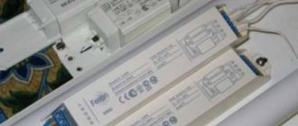
Imported components - lamp, choke, starter and capacitor
Some of the most reliable manufacturers: Philips, Osram, Sylvania, General Electric. Their cost is slightly higher, but a lamp with a gas-discharge lighting element will function more efficiently.
Thus, if you plan to connect a fluorescent light source using electronic ballasts rather than electronic ballasts, then you need to select a good quality starting device, since the duration of the lamp’s operation will depend on this.
The connection diagram also provides for the installation of a capacitor, through which the interference that occurs during operation is partially smoothed out. If, over time, some problems are noted during the operation of a lamp with a gas-discharge bulb, the starter must be replaced immediately, since untimely closing and opening of contacts brings the end of service of the lighting element closer.
How to choose: types and characteristics
For 2P base, the straightening speed should not be higher than 3 µm. It is advisable that the housing should be made of fire-resistant polycarbonate (optional). For 12 W lighting sources, the contacts should be no more than 2.2 cm long. It is advisable to choose orthogonal capacitors. It is this type of capacitors that will not cause problems with current conduction.
If you need to select a part for a 3P base, first of all, you need to pay attention to the inductance of the part. This parameter should be equal to plus or minus 2.5 Gn. In addition, you can choose the appropriate model by paying attention to:
- light source strength;
- starter type. This parameter depends on the type of throttle (electric, electromagnetic);
- the type of control mechanism that is located in the lamp;
- type of contacts (moving, asymmetrical, etc.);
- glow discharge current parameter;
- manufacturer.
One of the most important points when choosing a light source for fluorescent lamps is the company. A good thing cannot be cheap, so do not spare money on a quality manufacturer. Even consumables (such as a starter must be original and of high quality).
Let's look at the types of starters to understand which one is better and which one will be useful in each individual situation. Let us immediately note that there is no universal starter; everyone has pros and cons and specialization.
Service life, repair and replacement
Prolonged use of the starter causes a decrease in the voltage inside it, which leads to wear. This affects performance, the lamp begins to blink, and then stops starting altogether. This is due to the fact that when the lamp is used for a long time, the glowing charge decreases. If signs of a malfunction appear in the form of a blinking light, it is necessary to replace the faulty element in order to prevent failure of all equipment.
In addition to blinking, wear of the inductor due to overheating of the contacts and breakdown of the fluorescent lamp may occur. In order not to frequently change devices that are unsuitable for operation, you need to purchase high-quality starters that have proven themselves in the lighting market. Installing voltage stabilizers also has a positive effect on increasing the service life of lamps.
Replacing the starter is done as follows:
- turn off the lamp;
- remove the lampshade;
- Unscrew the faulty part counterclockwise;
- Insert the new starter into the groove and turn clockwise until it stops.
Appearance of starters and markings
To choose the right starter, you need to know:
- light bulb start type;
- manufacturer;
- electrical characteristics.
High-quality equipment is produced by Philips, Chilisin, Luxe, Osram. Cheap models of starters quickly wear out or lead to such an action as depressurization of the flask. In this case, the gases with which the lamp is filled begin to emit an unpleasant odor, all of which is also harmful to health. A good manufacturer completes its products with spare parts and gives a long warranty period, up to 6 thousand inclusions. Branded stores offer free replacement. If a defect is detected, branded stores will replace the part unsuitable for work free of charge.
Philips is considered the best manufacturer of starters. They are made from high quality materials. For example, heat-resistant polycarbonate is used to protect against overheating. The defect rate is 0.0001%. There are no radioactive components in the models of this company. Simple design and maintenance allow even an inexperienced person to install and replace equipment; you just need to follow the instructions.
Starters from this company are manufactured in the Netherlands. Model S2 is designed for low-voltage lamps with a power limit of 4–22 W.
The S10 model is more versatile. It can be used for high-voltage devices without power limitation.
All quality standards are met by domestically produced starters from Osram, which have a fire-resistant housing made of macrolon.
Before selecting a starter from a particular manufacturer, you need to pay attention to the following characteristics:
- life time;
- temperature regime;
- capacitor type;
- Rated voltage.
How to choose a suitable starter, knowing the operating voltage? The marking of domestic devices is regulated by GOST. The first two digits indicate power. The letter “C” is the purpose of the device (starter). The last numbers determine the voltage.
Example: 90C-220. This inscription must be deciphered as follows: the starter is designed for fluorescent lamps with a power of 90 watts and an operating voltage of 220 V.
When choosing imported starters, you should remember that they have different marking standards. For example, the designations S10, ST111 and FS-U indicate that the starter can be used in luminaires with a power range of 4–80 W, the mains voltage should be 220 V.
Popular makes and models
Many well-known manufacturers of lighting equipment are also manufacturers of starters, the most famous are: Philips, Osram, Sylvania and others .
(Netherlands) produces a wide range of products, including starters. The most modern and advanced of them are the series: “Ecoclick Starters”, “Safety & Comfort Starters”, “Green Starters”.
(Russia) produces a wide range of starters for different types and purposes of fluorescent lamps. Some modifications have special advantages over analogues from other manufacturers.
Such devices are considered:
- Starter fuses – DEOS® ST 171, DEOS® ST 172 and DEOS® ST 173;
- Automatic starters – DEOS® ST 172;
- Universal – DEOS® ST 171, DEOS® ST 172 and DEOS® ST 173.
Automatic starters turn off burnt out or faulty lamps and also restart them.
Starters used for special lamps deserve special attention, such as lamps for solariums. This type of equipment, lamps and components is produced (Germany). The company's product range includes electronic starters of varying power, heating time and operating temperature.
Starters are resistant to ultraviolet radiation, voltage 220/240 V, designed for a single switching circuit:
- PureBronze PBS-25, power 4 - 65 W;
- PureBronze PBS-100, power 80 - 100 W;
- PureBronze PBS-160, power 80 - 160 W.
The range of other manufacturers is also wide and varied, which allows you to choose a device according to the requirements placed on it, however, it is important to remember that you should not choose cheap models, because they usually use cheap materials, and this will negatively affect the service life of the device.
Possible faults
When using any lighting source, the question of repairing it and replacing failed elements always arises.
One of the reasons for the fluorescent lamp not igniting may be a faulty starter, the malfunction of which can be expressed as:
- The lamp does not light up;
- There is a glow at the ends of the lamp, but the lamp does not light up.
To replace the starter, you need to perform simple operations:
- Turn off the lamp;
- Remove the lampshade or other protective element of the lamp;
- Remove the faulty element - starter;
- Insert a new device into the base;
- Reassemble the lamp in reverse order;
- Turn on the lamp.
Replacing the starter is not difficult when there is a spare one, but if there is no such thing, then you need to make sure that the one removed from the lamp is exactly the element due to which the lamp does not burn. Its functionality can be checked in a simple way.
It is necessary to turn on the incandescent light bulb in series with the starter and apply voltage to them. If the starter is working, the light will light up and periodically turn off, and a characteristic click will be heard inside the starter. If the light does not light up, or lights up and does not blink, then the starter is faulty and definitely needs to be replaced.
Theoretically, it is believed that the service life of a starter is equivalent to the operating time of the lamp it lights. However, it must be taken into account that with increasing service life of the device, the intensity of the glow discharge voltage for starters of this type decreases, which affects the operation of the latter. However, all manufacturers of fluorescent lamps recommend replacing starters at the same time as replacing lamps.
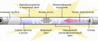
Operating principle of a fluorescent lamp
The peculiarity of fluorescent lamps is that they cannot be directly connected to the power supply. The resistance between the electrodes in a cold state is high, and the amount of current flowing between them is insufficient to cause a discharge. A high voltage pulse is required for ignition.
A lamp with an ignited discharge is characterized by low resistance, which has a reactive characteristic. To compensate for the reactive component and limit the flowing current, a choke (ballast) is connected in series with the fluorescent light source.
Many people do not understand why a starter is needed in fluorescent lamps. The inductor, connected to the power circuit together with the starter, generates a high voltage pulse to start the discharge between the electrodes. This happens because when the starter contacts open, a self-induction EMF pulse of up to 1 kV is formed at the inductor terminals.
Watch this video on YouTube
What is a throttle for?
The use of a choke for fluorescent lamps (ballast) in power circuits is necessary for two reasons:
- generation of trigger voltage;
- limiting the current through the electrodes.
The principle of operation of the inductor is based on the reactance of the inductor, which is the inductor. Inductive reactance introduces a phase shift between voltage and current equal to 90º.
From the fact that the current-limiting quantity is inductive reactance, it follows that chokes intended for lamps of the same power cannot be used to connect more or less powerful devices.
Tolerances are possible within certain limits. Thus, previously the domestic industry produced fluorescent lamps with a power of 40 W. A 36W choke for fluorescent lamps of modern production can be safely used in the power circuits of outdated lamps and vice versa.
Differences between a throttle and electronic ballasts
The throttling circuit for switching on fluorescent lighting sources is simple and highly reliable. The exception is the regular replacement of starters, since they include a group of break contacts for generating start pulses.
At the same time, the circuit has significant drawbacks, which forced us to look for new solutions for switching on lamps:
- long startup time, which increases as the lamp wears out or the supply voltage decreases;
- large distortions of the supply voltage waveform (cosф<0.5);
- flickering of the glow with double the frequency of the supply network due to the low inertia of the luminosity of the gas discharge;
- large weight and dimensions;
- low-frequency hum due to vibration of the plates of the magnetic throttle system;
- low starting reliability at low temperatures.
Checking the choke of fluorescent lamps is made difficult by the fact that instruments for determining short-circuited turns are few in use, and with the help of standard instruments one can only ascertain the presence or absence of a break.
To eliminate these shortcomings, circuits of electronic starting and control equipment (EPG) have been developed. The operation of electronic circuits is based on a different principle of generating a high voltage to start and maintain combustion.
Watch this video on YouTube
The high-voltage pulse is generated by electronic components, and high-frequency voltage (25-100 kHz) is used to support the discharge. Electronic ballasts can operate in two modes:
- with preheated electrodes;
- with cold start.
In the first mode, low voltage is applied to the electrodes for 0.5-1 seconds for initial heating. After the time has elapsed, a high-voltage pulse is applied, which causes the discharge to ignite between the electrodes. This mode is technically more difficult to implement, but increases the service life of the lamps.
The cold start mode differs in that the start voltage is applied to unheated electrodes, causing a rapid start-up. This starting method is not recommended for frequent use, since it greatly reduces the operating life, but it can be used even with lamps with faulty electrodes (with burnt-out filaments).
Electronic throttle circuits have the following advantages:
complete absence of flicker; wide temperature range of use; low distortion of the mains voltage waveform; absence of acoustic noise; increasing the service life of lighting sources; small dimensions and weight, possibility of miniature design; the possibility of dimming - changing the brightness by controlling the duty cycle of the electrode power pulses.
Blitz tips
If necessary, choose a replacement for a failed starter as follows:
- Pay attention to the lamp supply voltage;
- Determine the required power of the device;
- Choose a manufacturer based on pricing policy and required reliability.
Technologies do not stand still. The starter is now mounted directly into the base of fluorescent lamps with a standard socket; these lamps are called “economy lamps”. They are similar in their operating principles to fluorescent lamps, only their appearance is greatly changed.
Starters S2
Starters of this type are mainly manufactured by. The rectification coefficient of the models does not exceed 2.5 microns. If we talk about temperature parameters, then it is better not to use them in cold weather. Housings are most often made with polyurethane impregnation. In this case, the legs are used with small heads. Ballasts are standardly installed of the electromagnetic type. The starter choke is directly connected to the capacitor. However, in some models an additional lining is installed. The duration of heating of the cathodes in this situation depends on the power of the lamp. On average, a model of this type costs around 30 rubles.
S10 devices
Starters of this type are mainly manufactured by. If you believe customer reviews, their cases can withstand even extremely high temperatures. However, they are quite sensitive to high humidity. The rectification coefficient itself fluctuates around 3.5 microns. In this case, the inductance indicator does not exceed 5 H.
If we talk about design features, it should be noted that chokes are used with a glow discharge. However, in this case, much depends on the power of the lamp. If we talk about 20 V models, they use neon as a gas. Ballasts for such devices are suitable only of the electromagnetic type. The failure rate depends solely on the quality of the capacitor. Most often they are of the pass-through type. The capacitance of the capacitors fluctuates around 6.5 pF. A good starter for fluorescent lamps of this type costs about 40 rubles.
Starters
manufactures starters only using helium-hydrogen. In this case, there are many models on the market for P3 sockets. All starters have cylindrical bodies. Fire-resistant impregnation is provided in this case. The legs are directly installed with the heads. The capacitors in the devices are of the orthogonal type. Their capacitance fluctuates around 5 pF.
With interference suppression in starters, gaps occur quite rarely. The average failure rate is 0.2%. Radioactive isotopes are not used in the production of devices. It is also important to mention that the ballasts used are of the electromagnetic type. The average starter for fluorescent lamps from the presented company costs about 35 rubles.
Elements of “ignition” of light
The starter of various modifications ignites light sources that are powered by alternating current mains with a frequency of 50 Hz.
For this purpose, the lamp device has a ballast. In devices with glow discharge, after activation of the light source, increased voltage will begin to flow to the contacts.
The component itself is presented in the form of a small glass flask filled with gas. The flask itself is located in the inner part of the housing made of plastic or metal. In the lower part there is equipment consisting of two electrodes that come into contact with the lamp wires. Some models have a window at the top.
It is worth noting that it is the starters that most often break, after which the lamp cannot be turned on. But replacing them is not difficult if you know how to do it.
This component has the following functions:
- it starts first when connected to the network;
- responsible for heating the electrode;
- increases the current supply to the illuminator;
- closes and opens bimetallic plates;
- transmits current to the inductor.
If a part fails, the lamp simply will not turn on and begin to shine . Moreover, if a direct connection is made, the life of the lighting components is reduced. Starters are selected in accordance with the connection diagram.
Electronic ballast
The disadvantages of the electronic ballast circuit necessitated the search for a more optimal connection method. During the research, a method involving electronic ballast was invented. In this case, it is not the mains frequency (50 Hz) that is used, but high frequencies (20 – 60 kHz). It is possible to get rid of the flashing light that is harmful to the eyes.
Externally, the electronic ballast is a block with terminals exposed to the outside. The inside of the device contains a printed circuit board on which the entire circuit can be assembled. The unit is small in size, thanks to which it fits into the housing of even a small lighting device. Switching on is much faster compared to the EMPA standard. The operation of the device does not cause acoustic discomfort. This connection method is called starterless.
It is not difficult to understand the principle of operation of a device of this type, since there is a diagram on its reverse side. It shows the number of lamps for connection and explanatory notes. There is information about the power of the light bulbs and other technical parameters of the device.
The connection is made as follows:
- The first and second contacts are connected to a pair of lamp contacts.
- The third and fourth contacts are directed to the remaining pair.
- Power is supplied to the input.
Using Voltage Multipliers
This option allows you to connect a fluorescent lamp without using an electromagnetic balance. Usually used to increase the service life of light bulbs. The connection diagram for burnt-out lamps makes it possible for the light sources to work for some more time, provided that their power is no more than 20 - 40 W. Filaments are allowed both suitable for work and burnt out. In any case, the thread leads must be short-circuited.
As a result of rectification, the voltage doubles, so the light bulb turns on almost instantly. Capacitors C1 and C2 are selected based on an operating voltage of 600 Volts. The disadvantage of capacitors is their large size. As capacitors C3 and C4, preference is given to mica devices rated at 1000 Volts.
Fluorescent lamps are not compatible with direct current. Very soon, so much mercury accumulates in the device that the light becomes noticeably weaker. To restore the brightness of the glow, change the polarity by turning the bulb over. Alternatively, you can install a switch so you don't have to remove the lamp every time.
Connection without starter
The method using a starter involves prolonged heating of the light bulb. In addition, this part must be changed frequently. A scheme where the electrodes are heated using old transformer windings allows you to do without a starter. The transformer acts as ballast.
Bulbs used without a starter must be marked RS (quick start). A light source started through a starter is not suitable, since its conductors take a long time to heat up and the spirals burn out quickly.
Serial connection of two light bulbs
In this case, it is necessary to connect two fluorescent lamps with one ballast. All devices are connected in series.
To carry out electrical work you will need the following parts:
- induction throttle;
- starters (2 units);
- fluorescent light bulbs.
The connection is made in the following order:
- We connect starters to each light bulb. The connection is made in parallel. The connection point is the pin input at the ends of the lighting device.
- We direct free contacts to the electrical network. We use a choke for connection.
- We connect capacitors to the contacts of the light source. They will allow you to reduce the intensity of interference in the network and compensate for power reactivity.
How to check if the starter is working properly
Despite the simplicity of the design of the part, its failure can significantly damage the light source.
Important! If you have a faulty lamp with fluorescent light sources, you first need to check the functionality of the starting device.
The easiest way to check such a lamp ignition element is to replace it with a similar device. Replacing the starter is quite simple. If the fluorescent lamp starts working after this, then the cause of its malfunction was precisely the breakdown of the starter.
You can also determine the serviceability of the starter if you have special measuring instruments - a multimeter or tester. The multimeter is much more multifunctional than its analogue (tester).
Selecting a starter for certain technical characteristics of a fluorescent light source is not difficult. The user only needs to be guided by knowledge of the design of the ignition element, as well as understand the features of its mechanical and operational characteristics.
Particular attention should be paid to the marking of the starter, especially the power indicator and rated voltage. The effective performance of the lamp and its service life directly depend on the choice of a high-quality starter.