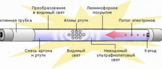
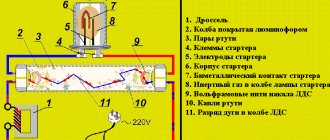
A fluorescent lamp (LL) is a glass tube filled with an inert gas (Ar, Ne, Kr) with the addition of a small amount of mercury. At the ends of the tube there are metal electrodes for applying voltage, the electric field of which leads to gas breakdown, the occurrence of a glow discharge and the appearance of electric current in the circuit. The glow of the gas discharge is pale blue and very weak in the visible light range.
But as a result of an electrical discharge, most of the energy passes into the invisible, ultraviolet range, the quanta of which, entering phosphorus-containing compounds (phosphor coatings), cause a glow in the visible region of the spectrum. By changing the chemical composition of the phosphor, different glow colors are obtained: for fluorescent lamps (FLLs) various shades of white have been developed, and for decorative lighting you can choose lamps of a different color. The invention and mass production of fluorescent lamps is a step forward compared to low-efficiency incandescent lamps.
What is ballast used for?
The current in a gas discharge grows like an avalanche, which leads to a sharp drop in resistance. To ensure that the electrodes of the fluorescent lamp do not fail due to overheating, an additional load is connected in series, limiting the amount of current, the so-called ballast. Sometimes the term throttle is used to refer to it.
Two types of ballasts are used: electromagnetic and electronic. The electromagnetic ballast has a classic transformer configuration: copper wire, metal plates. Electronic ballasts use electronic components: diodes, dinistors, transistors, microcircuits.
Incandescent lamps
For the initial ignition (start) of the discharge in the lamp in electromagnetic devices, a starting device is additionally used - a starter. In the electronic version of the ballast, this function is implemented within a single electrical circuit. The device turns out to be light, compact and is united by a single term - electronic ballast (EPG). The widespread use of electronic ballasts for fluorescent lamps is due to the following advantages:
- these devices are compact and light in weight;
- the lamps turn on quickly, but smoothly;
- absence of flicker and noise from vibration, since electronic ballasts operate at high frequencies (tens of kHz) in contrast to electromagnetic ones operating from mains voltage with a frequency of 50 Hz;
- reduction of heat losses;
- electronic ballast for fluorescent lamps has a power factor of up to 0.95;
- the presence of several, proven types of protection that increase safety of use and extend service life.
Connection diagram
Electronic ballasts have become an effective replacement for traditional circuits with chokes and starters, reducing the design of the luminaire and expanding its capabilities.
Connection diagram of one lamp to electronic ballasts.
Electronic ballasts do not have all the disadvantages of chokes. More than one lamp can be connected to one electronic ballast, and to some models up to four, without additional elements. The design works with standard lighting sources with a power of 18W, 36W, etc.
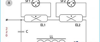
Connection diagram of several lamps to electronic ballasts.
It is better to place the block on the phase wire. If zero is present, the potential is maintained, which is expressed by slight flickering of the light source when the power is turned off. The phenomenon is typical for cheap ballasts.
To smooth out flicker, the capacitor is shunted with a resistor with a resistance of 100 kOhm.
Circuits of electronic ballasts for fluorescent lamps
Electronic ballasts are an electronic board filled with electronic components. The circuit diagram of the connection (Fig. 1) and one of the options for the ballast circuit (Fig. 2) are shown in the figures.
Fluorescent lamp, C1 and C2 – capacitors
Electrical diagram of electronic ballasts
Electronic ballasts can have different circuit designs depending on the components used. The voltage is rectified by diodes VD4–VD7 and then filtered by capacitor C1. After voltage is applied, capacitor C4 begins charging. At a level of 30 V, dinistor CD1 breaks through and transistor T2 opens, then the self-oscillator on transistors T1, T2 and transformer TR1 is switched on. The resonant frequency of the series circuit of capacitors C2, C3, inductor L1 and generator are close in value (45–50 kHz). The resonance mode is necessary for stable operation of the circuit. When the voltage on capacitor C3 reaches the starting value, the lamp lights up. At the same time, the regulating frequency of the generator and voltage are reduced, and the inductor limits the current.
Photo of the internal structure of the electronic ballast
Photo of a typical electronic ballast device
Efficient synchronous rectifier. Or a second life for electronic junk
Current rectification using a diode and transistor: advantages and disadvantages.
We will talk about a rectifier circuit using insulated gate transistors, English. Abbreviated as Mosfet.
The circuit uses the most common Mosfet with an induced N-conductivity channel. The main advantage due to which such switches are widely used in modern electronic devices in power circuits is their low resistance and voltage drop in the open state (no more than 0.1 V).
Here is a classic connection diagram for checking and studying the operation of a transistor with an N-channel:
Connection circuit for checking the Mosfet transistor
The opening of a switch with an N-channel occurs when a positive voltage is applied (charge the gate) to the gate (Gate) relative to the source (Source), respectively, in order to close the transistor, you need to discharge the gate, that is, the potential on it must be lower than the junction opening voltage. When open, the key conducts current in both directions.
Let me remind you that the circuit of such a transistor and the pinout are as follows:
There are features that need to be taken into account when rectifying current using such a transistor:
- presence of a parasitic diode between drain and source.
- The gate has a capacitance, which affects the response speed as the frequency increases.
The question arises: what is the efficiency of the rectifier on these transistors and why all these difficulties? Schottky diodes have long been invented, the direct drop at the metal-semiconductor junction of which is two times less than at the PN junction of a conventional silicon diode, but when low-voltage power supply and high current consumption are needed, the efficiency losses even on Schottky diodes are already significant!
Table of power losses on Schottky diodes when operating at different voltages:
| power supply voltage | drop on a Schottky rectifier diode | power dissipated by diode | losses |
| 12 V* 1 A=12 Watt | 0.4V 1A | 0.4 Watt | 4,8 % |
| 5 V* 2 A=10 Watt | 0.4 V 2 A | 0.8 Watt | 8 % |
| 3.1 V* 3 A=9.3 Watt | 0.4 V 3 A | 1.2 Watt | 11% |
In modern computer technology, where processor supply voltages can be within 1 V, the power supply of the entire computer is made at a higher voltage, while the efficiency does not suffer due to losses on the rectifier, and already in the circuit itself the voltage of the power supply is converted by pulsed step-down converters with using synchronous rectifier circuits based on Mosfet.
Below is a famous power supply circuit with low output voltage and using Mosfet as a rectifier.
Low Output Voltage Rectifier Using Mosfet Transistor
The upper winding of the transformer is the control winding of the transistor, the lower one is the power winding, the number of its turns determines the output voltage of such a rectifier, and the cross-sectional area determines the current. We'll look at the details below.
Second life of CFL electronic ballasts
Radio amateurs have long been widely using burnt-out “housekeeper” (CFL) boards with an electronic ballast circuit, as well as electronic transformers similar in design to power halogen lamps in their projects. Now this is relevant due to the transition to more efficient LED lighting; such electronic transformers and ballasts are no longer needed, and they can be used as a power source for other purposes after a simple modification.
The electronic ballast of energy-saving lamps can be repaired; there is an article about this: Repair of energy-saving lamps.
In the circuit of a standard CFL ballast, the modification consists of installing a jumper as shown in the diagram:
Electronic ballast repair
If it is not possible to quickly replace a failed electronic ballast, you can try to repair the ballast yourself. To do this, select the following sequence of actions to troubleshoot:
- First, check the integrity of the fuse. This breakdown often occurs due to overload (overvoltage) in the 220 volt network;
- Next, a visual inspection of electronic components is carried out: diodes, resistors, transistors, capacitors, transformers, chokes;
- If characteristic blackening of a part or board is detected, repairs are made by replacing it with a serviceable element. How to check a faulty diode or transistor with your own hands, having a regular multimeter, is well known to any user with a technical education;
- It may turn out that the cost of replacement parts will be higher or comparable to the cost of a new electronic ballast. In this case, it is better not to waste time on repairs, but to choose a replacement that is similar in parameters.
Electronic ballasts - what is it and how does it work?
Fluorescent lamps do not work directly from a 220 volt network. They need a special adapter that will stabilize the voltage and smooth out the current ripple. This device is called ballast equipment (ballast), consisting of a choke, which smoothes out ripple, a starter, used as a starter, and a capacitor to stabilize the voltage. True, the ballast in this form is an old unit that is gradually being phased out. The thing is that it was replaced by a new model - electronic ballasts, that is, the same ballast, only of the electronic type. So, let's look at electronic ballasts - what it is, its circuit and main components.
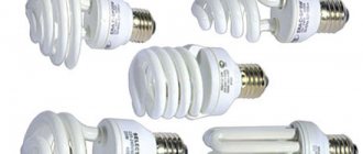
Electronic ballasts for compact LDS
Relatively recently, fluorescent energy-saving lamps, adapted for standard sockets for simple incandescent lamps - E27, E14, E40, have become widely used in everyday life. In these devices, the electronic ballasts are located inside the socket, so repairing these electronic ballasts is theoretically possible, but in practice it is easier to buy a new lamp.
The photo shows an example of such an OSRAM lamp with a power of 21 watts. It should be noted that at present, the position of this innovative technology is gradually being occupied by similar lamps with LED sources. Semiconductor technology, constantly improving, makes it possible to quickly achieve prices for LDS, the cost of which remains practically unchanged.
OSRAM lamp with E27 base
ECG FOR LED LUMINAIRES AND PANELS
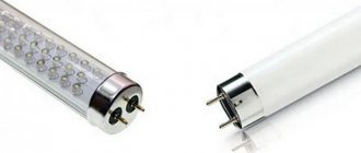
It should be noted right away that ballasts for LED lamps and other LED light sources do not exist! No matter what store sellers or online service consultants claim, this only indicates their incompetence.
LED light sources do not require starting devices such as electronic ballasts. A constant voltage source is required, and ideally a current stabilizer.
Such devices are called drivers. They generate voltage at the output terminals in accordance with the connected light source and limit or stabilize the output current within certain limits.
The fact is that LEDs function normally only in a narrow range of current flowing through them. A lower value reduces the brightness, and a high value causes a sharp decrease in service life up to the instantaneous burnout of the emitting diode. An LED, as a semiconductor element, has a pronounced dependence of the resistance value on temperature, so changing it by just a few degrees can cause a critical increase in current.
What is the difference between a voltage stabilizer and a current stabilizer?
To put it in simple words, a voltage stabilizer has a stable output voltage, despite the fact that the current consumption of connected devices can vary widely.
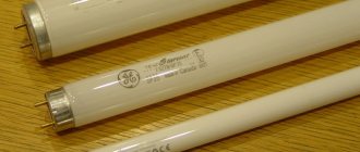
T8 fluorescent lamps
T8 lamps have a glass bulb diameter of 26 mm. The widely used T10 and T12 lamps have diameters of 31.7 and 38 mm respectively. LDS with a power of 18 W are usually used for lamps. T8 lamps do not lose their functionality during supply voltage surges, but if the voltage drops by more than 10%, lamp ignition is not guaranteed. Ambient temperature also affects the reliability of the T8 LDS. At sub-zero temperatures, the luminous flux decreases and failures in lamp ignition may occur. T8 lamps have a lifespan of 9,000 to 12,000 hours.
How to choose a driver for an LED lamp?
Voltage stabilizers for LED lamps are sold complete with the device itself and are manufactured for a specific model, but if necessary they can be purchased separately. Electronic ballasts constantly experience power fluctuations, so they usually wear out earlier than the LED element of the lamp, and sooner or later it will need to be replaced. The most commonly used are stabilizers for 36w and 40w lamps with a current of 350 or 700A.
While doing its job (converting alternating current to direct current), electronic ballasts consume a certain amount of electricity - approximately 20% of the lamp power. Therefore, when choosing a device, you need to multiply the lamp power by a factor of 1.2 - this will be the optimal driver power for this model. If the power and the LED do not match, their operation will be incorrect, the electronic ballast may overheat and quickly fail, or the LED will deteriorate.
The voltage stabilizer can be placed either inside the lamp (in a specially designated area of the housing) or separately. When placed inside the case, it is important to select the correct size driver.
Source: lt-electro.ru
How to make a lamp with your own hands?
You can make a simple lamp from two lamps as follows:
- select 36 W lamps that are suitable for color temperature (shade of white);
- We make the body from a material that will not ignite. You can use the housing from an old lamp. We select electronic ballasts for a given power. The marking should indicate 2 x 36;
- We select 4 sockets marked G13 for the lamps (the gap between the electrodes is 13 mm), a mounting wire and self-tapping screws;
- cartridges must be secured to the body;
- The installation location of the electronic ballasts is chosen to minimize heating from operating lamps;
- the cartridges are connected to the LDS sockets;
- to protect lamps from mechanical stress, it is advisable to install a transparent or matte protective cap;
- The lamp is fixed to the ceiling and connected to a 220 V power supply.
The simplest lamp of two lamps
How to connect EMPA
A few words about the design features of the electronic ballast. An electromagnetic ballast consists of at least an inductive ballast and an IZU pulse ignition device. The inductive ballast serves to accumulate electromotive force (EMF) before starting the lamp. The IZU directly provides the process of starting the lamp. If the kit includes a compensating capacitor, the efficiency of the electronic ballast increases. The capacitor shifts and smooths out peak values of power consumption, compensates for reactive power (it is not spent on performing useful work and is actually wasted). That is, using a capacitor increases the power factor of the lamp.
As a rule, electronic ballasts are sold wirelessly. Therefore, you will have to independently install the outlet to the network (three-core wire with a plug) and the output to the lamp socket (three-core wire no more than 1.5 m long + lamp socket). Electronic ballasts can be a closed type, when all elements of the system are hidden in a housing, or an open type.
Wiring diagram for closed-type electronic ballasts:
Unscrew the cover of the electronic ballast.
The outputs to the lamp and to the network are signed to avoid connection errors.
We mount the network cable with a plug to the electronic ballast.
We mount the wire for output to the lamp.
To do this, you will need a three-core wire with a length equal to the distance from the cartridge to the ballast. IMPORTANT: the distance between the IZU and the lamp should be minimal, since the quality of ignition of the lamp depends on this. The maximum permissible wire length is 1.5 m. You should not exceed it, because otherwise, the IZU may simply not light the lamp.
We clean the wires. We strongly recommend using special tips; this will simplify installation and protect you from troubles such as short circuits. The blue and brown wires are the negative and positive charges of the electric current, the yellow wire (sometimes green, there is also a striped yellow-green color option) is the grounding.
We mount one end of the wire with lugs into the lamp socket.
We mount the second end of the wire with lugs to the electronic ballast. Screw on the cover of the electronic ballast. Ready.
Installation of open-type electronic ballasts
If the electronic ballast is an open type, then the installation diagram will look like this:
Each of the two places where the wires are mounted is labeled. INPUT is for current input, that is, we mount a network wire with a plug here (to connect the electronic ballast to the network). OUTPUT is for current output, that is, we mount the wire going to the lamp into it.
We unscrew the bolts, maybe not all the way, the main thing is to lift the fixing plastic panel so that the wire can pass through. The signed inputs N and L are positive and negative charges. Accordingly, we install blue and brown wires in them. IMPORTANT: if at INPUT you connected the blue wire to N, and the brown wire to L, then at OUTPUT the wires should be connected in exactly the same way - blue wire to connector N, brown wire to L. The ground wire (yellow or green) is connected centrally to the appropriate input, indicated by the “ground” symbol.
Thus, on INPUT we have a wire with a plug for connecting to the network, on OUTPUT we have an output wire to the lamp socket. Installation of the second end of the wire going from the ballast to the lamp socket is carried out in the same way as shown above, in the version with a closed type ballast. The maximum permissible wire length is also 1.5 m.
How does an 18 W electronic ballast work for LED lamps?
A new EMF for an LED lamp , purchased at any store, consists of the following components:
- High-quality frequency filter , which smoothes out low-level interference and is aimed at the product leads. Such a filter helps reduce the impact of the LED lamp on other household equipment, for example, the amount of interference from radios or televisions.
- Powerful rectifier , which converts alternating voltage into direct voltage in a circuit.
- Small inverter.
- Various special components that are necessary to adjust the power in the LED lamp circuit.
- Small-sized constant voltage filter .
- A high-quality inductor that limits the maximum current in the circuit.
The inverter is also often equipped with a device that is responsible for smoothly adjusting the brightness of the LED lamp.
What is an electronic ballast and its purpose in a fluorescent lamp
Fluorescent lamps have some disadvantages that become noticeable after turning on the light. The strong hum and frequent flickering of light observed during the operation of such built-in lamps can disturb the mental balance of any person. The only solution to this problem is to install a special ballast called electronic ballast.
The production of fluorescent lamps was conceived for the development of lighting systems that used conventional incandescent lamps, which had an extremely short service life. The maximum service life of an incandescent lamp is about two thousand hours, which cannot be compared with the durability of fluorescent lamps, which has more than 16 thousand hours. In addition, fluorescent lamps have a good luminous flux, which exceeds the light from conventional lamps by more than six times .
Advantages and disadvantages of 18 W electronic ballasts
Experienced electricians highlight several main advantages of using electronic ballasts in the operation of fluorescent lamps. These include, first of all,:
- Saving maximum light power while reducing the amount of electrical energy consumed by the power supply.
- Lack of strong flicker of light , which is considered a feature of fluorescent lamps.
- Reducing noise during lamp operation.
- Long service life of the lamp, which became possible due to the use of an electronic ballast device.
- Convenient control of the brightness of the fluorescent lamp.
- Resistance to fluctuations and differences in operating voltage in the electrical power supply network.
- Big savings in terms of subsequent replacements of the main parts of the lamp. Due to the fact that the smoothest starting mode of the product will be used with the help of the power supply, this can increase the service life of starters and fluorescent lamps.
The main disadvantage of using electronic ballasts is, like other new technologies and products, the very high cost compared to other similar power supplies.
Source: instrument.guru
Why do you need ballasts?
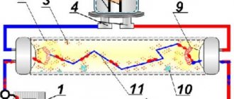
Before we start talking about the throttle, let's figure out what ballasts are and what they are needed for. In order to answer these questions, it is necessary to understand how a fluorescent lamp (FLS) works. Let's take a look at its schematic representation.
In front of us is a glass flask in the form of a tube, into the ends of which two tungsten spirals are soldered - the anode and the cathode. The tube itself is filled with an inert gas with a small addition of mercury. If operating voltage is applied to the anode and cathode, the lamp will not light up - the resistance of the inert gas is too high, and there will be no current between the electrodes.
In order to start the device, it is necessary to warm up the coils. As soon as they warm up, thermionic emission begins, the same as in a conventional vacuum tube for radio receivers. Current will begin to flow between the electrodes, and mercury vapor will begin to emit ultraviolet light. When ultraviolet light hits the phosphor, it causes it to glow brightly. UV radiation itself is almost completely absorbed by glass and phosphor.
The start of the DLS is ensured by a special device - a starter, which briefly supplies voltage to the coils (we’ll talk about its switching circuit later). It is the starting part of the control gear.
Starters for launching DLS
You can make the lamp work (as they say, “start”) in another way, by briefly applying increased voltage to the electrodes. This is exactly how electronic ballasts work, which we’ll talk about later.
But after starting the LDS, new problems begin: the glow discharge in the bulb turns into an arc and instantly leads to a short circuit. To prevent this from happening, the current through the lamp must be limited during operation. This role is played by another device - electromagnetic ballast. It is the regulating part of the ballast equipment.
Electronic ballasts for LDS with a power of 36 W
Thus, without a starter the lamp will not start, without ballast it will burn out. The complex of these two devices is called ballast control. Now, I think you understand why ballasts are needed, and that you can’t do without them.
Important! The power of the choke must match the power of the lamp. Otherwise, the lamp will either go out immediately, or will not start at all, or will burn out.
This is interesting
Currently, electronic ballasts are installed not only with gas-discharge light sources, but also with halogen and LED lamps. In this case, you cannot use one device designed for one type of lamp to another lamp. Firstly, they won’t fit the parameters. Secondly, they have different schemes.
When choosing an electronic ballast, it is necessary to take into account the power of the lamp in which it will be installed.
The optimal model option is devices with protection against non-standard operating modes of the light source and against their deactivation.
Be sure to pay attention to the position in the passport or instructions, which indicates in what weather and climatic conditions the electronic ballast can operate. This affects both the quality of operation and service life.