All pass-through TV sockets have an inlet and an outlet. The output wire is connected to another outlet or directly to the TV. Their main disadvantage is the deterioration of the output signal by 4 dB.
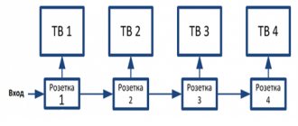
Connection diagram for several TVs through pass-through sockets:
You should also initially pay attention to the signal transmission frequency of the outlet. Models with frequencies up to 1000 MHz are designed to work in networks with cable or terrestrial television. Instances with a frequency of over 1000 MHz are used for satellite television.
Connecting the cable
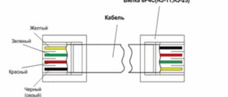
To connect the cable, remove the insulation from the central core by 6-8mm. In this case, you need to retreat another couple of millimeters from the edge of the outer shell to the point where stripping begins.
Next, insert the TV wire into the socket and check through the viewing window that the central core goes all the way into the connector.
In the Unica series it is self-clamping, there is no need to tighten anything here. Other brands may have a clamping screw, which will need to be loosened first and then tightened with a screwdriver.
Pay special attention so that the “hairs” of the screen do not touch the central core anywhere.
All that remains is to tighten the cable itself with the central screw and put the outer cover in place.
If something is not clear and does not work out, you can always refer to the instructions.
Connecting a Legrand Valena TV outlet
Installation of the socket, as usual, begins with its disassembly. The outer frame is attached here with latches. From the reverse side, press them with your fingers and remove the frame.
Next you need to get to the inside of the outlet. Insert a screwdriver into the slot and open the protective cover upwards.
Inside there is a seat for the central core. In front of it there is a wedge-shaped pin, which is driven under the top layer of insulation.
Strip the coaxial cable and expose the central core by 8mm. In this case, the outer screen remains completely under the insulation layer. There is no need to expose wires and foil.
Insert the cable into the socket so that the wedge penetrates under the outer shell of the insulating layer. The central core should go into its seat.
Again, note that there is no need to expose the screen here. The wedge-shaped stop itself goes under the insulation and forms contact.
Make sure that all contact parts of the socket and cable are in reliable contact with each other:
- central core in the seat
- wedge under insulation
- the wire is pressed tightly to the side frame
After this, close the lid with a simple movement. Next, the frame together with the cable can be easily rotated in different directions and mounted on the socket box.
Connecting a cable without a TV socket
Is it possible to make a TV cable exit from the wall as neatly as with a socket, but without using it? You can, but you will still get 3 advantages of such a connection:
- no need to buy an expensive TV socket (cost savings reach up to 5 times the value!)
- there is no need to install a separate piece of cable to connect the TV connector to the outlet
- there is no degradation in signal quality. On the F connectors of the UHF range, the signal attenuates only from 0.1 to 0.3 dB.
All this is achieved by using ordinary plugs. Initially, lay a sufficient supply of cable in the wall so that it is enough for direct connection to the TV (1-1.5 meters).
Drill a hole in the plug to the diameter of the cable and bring the conductor out through it.
It all looks as beautiful as on an ordinary outlet.
The only negative is that not all manufacturers have this kind of plugs and may not be available on certain series.
Connection errors
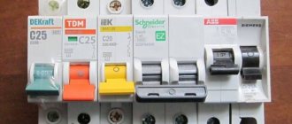
The three most common mistakes made when connecting TV sockets:
1Use of sockets with 75 Ohm resistors for digital television cable.
The result is a complete absence of a signal, or its poor quality.
If you have an analog signal, and several TVs are connected in series through a special splitter, then the resistance here will also be unnecessary and it is better to get rid of it.
2Use of sockets with serial connection without resistors, in analog networks with empty connectors.
If no equipment is connected to these connectors (sockets), other TVs will again display some of the channels poorly and experience interference.
3Completely “wrapping” all the screen veins with the top layer of foil when cutting the cable.
As a result, only the inner part of the foil remains outside, which is not conductive. Accordingly, there will be no contact between the screen and the socket connectors.
Source
Share the news on social networks
- Related Posts
- What is the difference between LED strips - 3 characteristics - smd 3528, 5050, 2835, 5630
- Smart search for cables in the ground - electronic marker, what is it.
- DIN rail terminal blocks - assembly secrets, errors and connection rules. Screw terminals.
« Previous entry
How to connect a legrand antenna socket
Switches, sockets, dimmers and other electrical installation equipment of the Valena series manufactured by Legrand
European solution for stylish and modern home and office decoration. The Valena Legrand line is represented by a large number of devices, the presence of which will make a person’s life comfortable in the 21st century: electrical sockets, USB/TV/FM/Audio/Telephone sockets, dimmers, thermostats, switches and switches of various types and much more. A large number of color schemes and decorative frames will allow you to adapt the series to a variety of design solutions.
The screw clamp and automatic terminal mechanisms used in Valena sockets make it possible to ensure a stable power supply in a wide variety of conditions.
An example of a complete set of Valena series devices
Questions and answers about the Valena series
What is the difference between pass-through, terminal and single TV sockets?
To answer the question of how different types of television sockets differ, let’s first understand the basic diagrams for laying and connecting a TV cable. There are 2 main circuits for connecting television cables and sockets - parallel, also known as “star” , and serial, also feed-through, also known as “loop”.
The main feature is that to build a parallel circuit it will be enough to buy a splitter (splitter) at the input and 4 single or 4 terminal sockets (of course, if you plan to connect 4 TVs). Such sockets are available in all popular and sought-after series: Unica, Glossa, Valena, Basic55, etc. This option is the simplest and most understandable.
With the pass-through system, everything is a little more complicated. To connect 4 TVs to one cable you need to buy 3 pass-through sockets and 1 terminal socket. A pass-through TV socket is very similar to a regular one, but it has 1 cable input and 2 outputs (1 for connecting a TV, 1 for connecting the next pass-through socket).
Pass-through TV sockets are designed for higher signal amplitude losses (4db), while conventional TV sockets are designed for only 1db. This is due to the fact that when one cable passes through a series of obstacles (sockets), the signal loses its power, the picture quality becomes worse - this is why “stronger” sockets are installed.
The main disadvantage of connecting with a cable is that if the cable between one of the sockets is damaged, you will have to open the walls to identify the fault.
The most popular terminal and single TV sockets
The most popular pass-through TV sockets
Connection instructions
Installing an open type socket
This is the simplest installation option and takes no more than 10 minutes.
Installation is carried out in the following order:
- socket terminals and securely clamped.
- The socket is installed at the bottom of the wall or on the floor using screws.
- In order to hide external wiring, electrical baseboards or panels are used, inside which telephone wiring is installed.
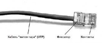
TV cable device RG-6U
The television cable consists of 4 parts (see photo below):
- PVC sheath
- External conductor (screen), consisting of metal braid and foil coated with a layer of aluminum
- Dielectric - insulation made of polyethylene or semi-air dielectric filling
- Internal conductor represented by a single copper core
I would like to note that the TV cable can be presented in another design, for example, the screen can consist of copper wires, and the internal conductor can be multi-core, but we will focus on this design.
Characteristics of sockets
Having looked at the connection diagrams and types of sockets, we already have an idea of what we need. But there are still a number of parameters that are worth paying attention to when choosing TV outlets.
We will talk about them in this section:
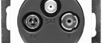
- Legrand TV socket can have several types of connectors. This can be a TV connector - that is, for receiving an analogue television signal, an R - a connector for receiving radio and a SAT connector for receiving satellite television. All these types differ not only visually.
Standards of domestic GOST
- The TV connector is designed to transmit signals in the range 5 – 862 MHz. The R connector transmits signals in the range from 87.5 to 108 MHz, and the SAT connector transmits signals in the range from 950 to 2400 MHz.
Note! The TV connector in Legrand sockets is made in accordance with the European standard DOCSIS v.2.0. But our standard: GOST R 52023 applies to a wider range of 40 - 1000 MHz. This does not play a significant role in the quality of signal transmission, but is a discrepancy between the product and the standards established in our country.
- Also, when choosing, you will probably come across the concept of pass attenuation. Typically its value is within 1 - 2 dB. In particular, for any Legrand TV outlet, it is 1.5 dB. This attenuation is caused by contact connections and is very conditional, so you don’t have to pay much attention to it.
Technical parameters of Legrand sockets
- But you should definitely pay attention to the attenuation on the branch, which is available at pass-through sockets. Typically it is between 10 and 15 dB. For Legrand sockets it is 14 dB. For terminal sockets it is usually slightly lower, about 10 dB.
- The last difference is the way the cable is attached to the outlet. Typically, all TV sockets are secured using screw or spring clamps. This requires cutting the cable.
Rules for installing sockets with automatic terminals
The Legrand company has developed its own method of quick installation. It allows you to do the installation yourself without cutting the cable. But not all models are equipped with such a device, so when purchasing, make sure that the outlet is equipped with automatic terminals.
Installing a socket in a socket box
Installation of the assembled television socket at the mounting location is carried out using spacer tabs present in its design. The socket itself is additionally fixed in the wall with mounting screws. Before installing them, check the installation geometry by level and, if necessary, adjust the position of the legs.
How to install a LeGrant TV socket, watch the video below:
In general cases, the TV is connected to a cable that is located in the wall. Of course, there is a special connector, but then you have to hide the extra wire behind some cabinet or cabinet, which is not always convenient. To avoid such inconveniences, connect the cable to the TV outlet. The remains of the wires are hidden behind the wall, which makes the appearance much neater. We will analyze the features of this device in the proposed article, and if this is your first time encountering this, photos of TV sockets will bring you up to date.
Types of television sockets
First of all, let's define the types of television sockets and their scope of application. You might be surprised, but there are different types of sockets designed for different circuits. These can be single or regular sockets, pass-through and terminal.
Using a socket that does not comply with the connection diagram will lead to a decrease in signal quality. Therefore, at the first stage, let's look at the options for connection diagrams.
Star circuit
A single Legrand TV socket is designed for installation using a star connection.
The manufacturer calls the connection type topology. And this type of sockets can only be used with a star topology.
| The peculiarity of this type of connection is that the cable from the antenna or other signal source goes to the so-called multiplier - or, as it is more correctly called, a splitter. In this device, the signal is divided into the required quantity without losing its quality. Cables are connected to the splitter, which distribute the signal to each individual outlet. |
| There are two types of signal multipliers. Some are capable of passing the amplifier voltage, others are not capable of this. But before we deal with this issue, let's decide: do we need an amplifier at all? |
| An amplifier is a device that supplies 5, 10 or 12V voltage to the antenna. This allows you to increase the signal level. According to GOST 28324-89, the normal signal level should be in the range from 53 to 83 dB. If your antenna is installed in the line of sight of the repeater, then this signal level is probably there, and as the instructions say, you simply do not need an amplifier. |
| If your antenna is blocked from the repeater by houses or landscape, then you are receiving a reflected signal. Moreover, the signal can be reflected several times and is therefore very weak. In this case, you simply need an amplifier. |
| Having decided whether we need an amplifier, we can return to the issue of connecting a splitter. If our splitter is capable of passing amplifier current, then usually the inscription “Power in”, “+12V” is written on one of the terminals, or simply a color designation is applied to this channel. The fact is that only one multiplier channel can pass the amplifier signal. And this should be taken into account when connecting. |
| For the most part, splitters do not have the function of transmitting an amplifier signal. In this regard, its power supply must be organized for the supply cable of the television network. |
Note! According to the European standard CENELEC EN 50083-7, the optimal signal level is considered to be 53 – 74 dB. That is, the upper limit is slightly lower. But you shouldn’t chase the maximum signal level. Increasing it can lead to the exact opposite consequences - deterioration in image quality.
A single Legrand TV socket is connected with a cable to the multiplier. Each outlet in the circuit receives the same signal level, which is almost equal to the signal arriving at the splitter.
This is the main advantage of this scheme. The disadvantages of the star scheme include the need to install additional equipment - a splitter and higher TV cable consumption.
Passage scheme
Pass-through (see Pass-through TV socket: how installation is performed) and terminal sockets are designed for feed-through topology. The peculiarity of this scheme is that it does not require additional devices, but can only be used for analog television.
Pass-through connection diagram
So:
- The essence of this circuit is that the first socket is powered from the antenna. From the first outlet the second, and so on. The last socket in this scheme is installed. All other outlets must be pass-through.
- A logical question arises: what is the difference between a Legrand TV pass-through socket and, say, a single socket. The fact is that a working TV superimposes its signal on the cable coming from the outlet. As a result, a superimposed image or simply interference may appear on the second TV in the circuit.
Pass-through TV socket
- To exclude this, special filters are used. They are built into the outlet and completely block the interference created by the TV. But, like any other protective device, a filter is a resistance that reduces the signal level.
- And we remember that the signal arriving at the first socket should be within the range of 57 - 83 dB. Each such filter loses 10 to 15 dB. Plus switching losses in the outlet itself. And it turns out that the pass-through circuit is capable of providing a high-quality signal for only two or three sockets in the circuit. A larger number will reduce the signal level below acceptable limits.
- As you can see in the video, the terminal socket differs from the pass-through socket only in the number of pins. If two cables can be connected to a pass-through socket - supply and output, then only the appropriate one is connected to the terminal socket. And the filter of such an outlet, in most cases, has a slightly lower resistance.
Termination TV socket
As a result, it turns out that the pass-through scheme has such an advantage as the cost of installation, because the TV cable needed is an order of magnitude less, and there is no need for additional equipment - as well as installation time.
At the same time, in terms of signal quality, it is much inferior to the star circuit. Indeed, with this type of connection, each subsequent outlet has a lower signal level.
Connection diagrams
There are many schemes for connecting a TV connector. A splitter is used to process the signal. This device looks like a small box and performs the function of signal separation. Just like in telephone lines, when transmitting digital electrical signals, you cannot do without their separation.
The principle of operation of a splitter is to divide the signal into equal packets. Next, the divided segments are transmitted to the input part of the television connectors. The splitter is designed in such a way that all TVs receiving the signal, regardless of their number, will receive a signal of equal quality. As a result, within the same apartment there is no point in having a separate antenna for each TV.
The connection can be made in one of two ways:
- The “star” scheme, when the old cable is removed and the new one is laid through the splitter.
- Daisy chain circuit.
Below we will look at the question of how to connect an outlet, while paying attention to the advantages of the circuits under consideration.
Star pattern
This circuit uses a splitter that performs the function of branching the signal, breaking it into packets and amplifying it. The device is placed at the cable entrance to the living space from the entrance. Next, antenna conductors are distributed to consumers. Installing a TV outlet using this simple technology is most often used, since the splitter provides a number of advantages:
- The cable is located in a technically protected place, which is important both during installation work and during further preventive inspections.
- The signal is stable.
- Separated signal packages are uninterruptedly supplied to all television receivers in the apartment.
Daisy chain connection
This method of installing a TV outlet involves the use of a cable. The main cable is routed to any of the TVs in the house, and then it is routed to other receivers directly at the connector. The wiring is a branch into two or more parts (depending on the number of TVs available).
Connecting in this way is called daisy chain. In this case, the connectors connected by a cable must be feed-through, except for the last one, which is the terminal one.
The daisy chain circuit allows you to save on cable consumption, but it also has disadvantages. The disadvantage of a daisy chain system is that the quality on the first receiver will be higher than on subsequent ones. However, if the television signal is strong enough, the difference will be almost unnoticeable. In addition, one should take into account the fact that modern television equipment is equipped with the ability to amplify the signal, and this happens automatically.
Daisy chain connection via pass-through television sockets
So, the uneven distribution of the signal in this case can be considered an insignificant drawback. Other disadvantages of the loop system include the following:
- The circuit, where there are pass-throughs and a terminal TV socket, will cost more than the standard “star” circuit.
- If the circuit breaks, all subsequent consumers are deprived of a television signal.
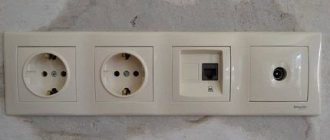
Installation using the example of a Schneider socket
As an example, let’s look at the installation of a pass-through socket from a French one (model socket tv rj45). The task is to connect two TVs to one cable using a loop-through circuit.
When installing a socket for a TV cable, we provide a small excess of the cable itself - it should come out of the installation box. Next, we strip a small section of the insulating material on the cable. At the same time, we keep the central core and shielding braid intact.
We start by removing the front panel and slightly unscrew the clamping bolt. This is necessary to ensure that the cable exits freely through the hole.
There are arrows on the connector body. Insert the cable all the way in the direction indicated by the arrows. Then we press the cable with a clamping screw (tighten it). The cable must be securely fastened, but the screw must be tightened with care so as not to crush the line. We perform exactly the same manipulations with the second end. We install the connector in such a way as to avoid kinks on the cable.
Note! Before installing a television outlet, you should inspect the area where the wire is fixed for the possibility of a short circuit in the main core with the braid.
When the cable is inserted and secured, put on the front panel. The panel is fixed using special proprietary latches. Using a building level, we check the accuracy of the horizontal installation of the connector. If everything is in order, we finally fix the panel with fastening bolts and cover it with a frame.
Connecting the Lezard connector
Sockets from are inexpensive and of good quality. However, when choosing Lezard products, you need to take into account the presence of a printed circuit board on it. The fact is that the boards are equipped with a component such as a capacitor. This part is located next to the center core retainer and the cable connector. The capacitor is impermeable to the supply voltage that must be supplied to the active antenna. Therefore, such connectors are suitable exclusively for passive antennas.
If you still want to adapt such a socket for an active antenna, you need to install a standard conductor instead of a filter capacitor. This is done by short-circuiting and soldering a piece of copper wire instead of the capacitor.
The actual connection of a TV socket consists of installing the signal conductor of the TV cable in the central socket terminal. You also need to secure the screen with a bracket.
Note! The main conductor that transmits the signal must not be short-circuited with the braid. Otherwise, the screen that protects against loss of the television signal in the cable will be damaged.
Connecting the Legrand connector
The TV socket differs from the French one in its ease of connection, but is also quite expensive.
When connecting the connector, fix the central cable core in a special spring clamp. We press the foil braid to the body using a folding fastener.
We remove the fastening cover, which covers the connection areas of the coaxial cable. To do this, carefully pry off the cover with a screwdriver, thereby releasing the latch.
We remove the outer insulating layer and the internal dielectric material of the cable about a centimeter in length. We direct the cable into the connector, and fix the copper core with a self-clamping terminal.
Note! Contact of the braid with the socket body is achieved thanks to a plate that connects to its outer insulator, firmly pressing against the cable screen.
When the cable is connected to the connector, install the latter in the socket box. We secure the socket with a pair of self-tapping screws. Next, we clamp the screws with spacers of the socket clamps. We tighten the screws of the socket until they stop. Place the front panel of the connector in its proper place. The TV socket on the wall is installed and ready for use.
Author: Administrator incl. January 19, 2016. Published in DIY
First, let's get acquainted with what a coaxial cable is and how to choose it, which, after laying the wiring in the wall of a building or apartment, is subsequently connected to a TV outlet, and then connected to a TV or sat/TV receiver.
As you already understand, a coaxial cable for satellite and terrestrial antennas is a structure, the main part of which is the central copper core - the central conductor through which the satellite or terrestrial TV signal passes to the TV or sat/tv receiver. The braid and foil (Screen) are both a negative contact and protection against signal loss and electromagnetic interference in a coaxial TV cable.
TV socket Legrand Valena 694284 single hidden installation white
Availability
Available from pick-up warehouse
Designed to connect a TV using a TV cable to an antenna. Installed together with the frame. Single TV sockets are used to connect a television cable when laying out a cable network in a house according to the “star” principle.
We guarantee delivery on time!
If we are late, delivery is free.
Single TV sockets are used to connect a television cable when laying out a cable network in a house according to the “star” principle. In other words, the cable from the antenna is connected to the television splitter, and from it it radiates through the rooms to the sockets. This is the most common and effective scheme.
Degree of protection against dust and water
IP 20 (The first number (from 0 to 6) indicates the degree of protection against the penetration of foreign objects and dust into the product, the second (from 0 to indicates resistance to moisture. The higher the numbers, the higher the protection).