One of the elements of an electrical circuit that has a constant (certain) value of resistance to electric current is a constant resistor. Translated from Latin, resisto means “I resist.” With the help of such a part, a linear transformation of current (I) into voltage (U) and vice versa occurs. A resistive element can limit the amount of current and absorb electrical energy. Variable resistors allow you to manually vary the value of their resistance.
Variable resistors, appearance
Potentiometers
A variable resistor (VR) and a potentiometer are two different definitions of one device. At the beginning of the development of radio electronics, it was believed that by changing the position of the moving contact on resistive coils with wire windings, the potential difference was measured. Therefore, two words: “potential” and “measurement” are included in the definition of a potentiometer. This is a variable resistor. Today there are many such components of electronic and electrical circuits, and their names are different. The voltage is adjusted with a potentiometer, and the current with a rheostat.
Important! The operating principle of such elements is the same. They change their output resistance depending on the position of the moving contact or brush, which is driven under the influence of external influences.
Non-wire
Resistors of the SP type belong to composite non-wire elements. They have the following design:
- base made of insulating material;
- film, current-conducting element;
- moving contact;
- axis with moving system.
Non-wire variable resistors also include SPO, VK, SPZ, TK.
A carbon conductive film is applied to the getinax plate (base). Its composition can be composite: bakelite resin and carbon black. The element leads are attached to the ends of the layer. To do this, it is coated with silver paste for contact pads. At specified angular intervals, a slider (moving contact) slides across the film, which is driven from the axis of the resistor.
For your information. The end of the axle is molded for ease of adjustment: a slot (slot) for a screwdriver or a recess for securing the handle.
Non-wire potentiometer device
Resistance may change as the angle of rotation changes. The angle varies from 0 to 2500.
Wire
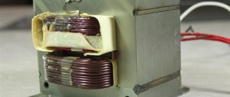
In resistive variable elements of this type, high-resistance wire is used instead of a conductive film. It is laid in one layer turn to turn. The contact slides along these turns.
Structure of a wirewound variable resistor
A wirewound potentiometer consists of the following elements:
- frame for winding;
- winding;
- unit with an axis of rotation;
- movable brush.
Typically, frames are either bent from plates with wire already wound, or it is wound on rings. The plate frame is made of insulating material or metal.
Attention! Bent plate bases do not have precise geometric parameters, although they are easy to manufacture.
High precision when creating potentiometers is obtained using rings made of ceramic, metal or plastic. In this case, winding is carried out with special equipment - a shuttle, on which the required amount of wire is collected. The wire itself can be nichrome, manganin with enamel insulation.
Interesting. One such wire material is constantan alloy (59% Cu; 40% Ni; 2% Mn). It is an alloy of copper and nickel with the addition of manganese. Edward Weston invented it in 1888 for instrument coils. Constantan resistance is independent of temperature changes.
The wire insulation is ground to a depth of 0.25d. This is necessary for reliable connection of the brush with the winding during movement.
Appearance of the sliding edge
Electronics for everyone
It seems like a simple detail, what could be complicated here? But no! There are a couple of tricks to using this thing. Structurally, the variable resistor is designed in the same way as it is shown in the diagram - a strip of material with resistance, contacts are soldered to the edges, but there is also a movable third terminal that can take any position on this strip, dividing the resistance into parts. It can serve as both an overclockable voltage divider (potentiometer) and a variable resistor - if you just need to change the resistance. The trick is constructive: Let's say we need to make a variable resistance. We need two outputs, but the device has three. It seems that the obvious thing suggests itself - do not use one extreme conclusion, but use only the middle and second extreme. Bad idea! Why? It’s just that when moving along the strip, the moving contact can jump, tremble and otherwise lose contact with the surface. In this case, the resistance of our variable resistor becomes infinite, causing interference during tuning, sparking and burning out of the graphite track of the resistor, and taking the device being tuned out of the permissible tuning mode, which can be fatal. Solution? Connect the extreme terminal to the middle one. In this case, the worst thing that awaits the device is a short-term appearance of maximum resistance, but not a break.
Fighting limit values. If a variable resistor regulates the current, for example, powering an LED, then when brought to the extreme position we can bring the resistance to zero, and this is essentially the absence of a resistor - the LED will char and burn out. So you need to introduce an additional resistor that sets the minimum allowable resistance. Moreover, there are two solutions here - the obvious and the beautiful. The obvious is understandable in its simplicity, but the beautiful is remarkable in that we do not change the maximum possible resistance, given the impossibility of bringing the engine to zero. When the engine is in the uppermost position, the resistance will be equal to (R1*R2)/(R1+R2) - the minimum resistance. And at the very bottom it will be equal to R1 - the one we calculated, and there is no need to make an adjustment for the additional resistor. It's beautiful!
If you need to insert a limitation on both sides, then simply insert a constant resistor at the top and bottom. Simple and effective. At the same time, you can get an increase in accuracy, according to the principle given below.
Increased accuracy. Sometimes it is necessary to adjust the resistance by many kOhms, but adjust it just a little - by a fraction of a percent. In order not to use a screwdriver to catch these microdegrees of rotation of the engine on a large resistor, they install two variables. One for a large resistance, and the second for a small one, equal to the value of the intended adjustment. As a result, we have two knobs - one “ Coarse ” and the other “ Precisely ”. We set the large one to the approximate value, and then use the fine one to bring it to perfection.
Basic PR parameters
Like any element of radio engineering and electronic technology, the potentiometer has its own physical and electrical characteristics. These include the following points:
- Rnom – nominal resistance (total), Ohm;
- Pnom – rated power, W;
- Rmin – minimum resistance value, Ohm;
- functional type of change in resistance;
- wear resistance;
- the amount of noise during adjustment;
- dimensions.
Equivalent resistance
Price and operating features under the influence of various external factors also relate to the characteristics of a passive resistive two-terminal network.
Nominal resistance
As for the marking of a variable resistor, a figure for the value of the nominal resistance is applied to its body, without indicating the permissible deviation (±30%).
Attention! Standard series Rnom for Russian parts (according to GOST 10318-74) – 1.0; 2.2; 3.3; 4.7 Ohm (kOhm, Mohm). For imported elements – 1.0; 2.0; 3.0; 5.0 Ohm (kOhm, Mohm). Exact data for individual brands can be clarified in the directory.
The resistance between pins 1 and 3 is called total or nominal.
Markings on the body
Functional characteristics form
The change in R between terminals (middle and extreme) can occur according to different laws. This is called functional characteristic (FC). It can take the following forms:
- linear – R changes in direct proportion to the movement of the slider;
- nonlinear - changes occur in a given order.
There are three forms of change in R that can be considered basic:
- linear - A;
- logarithmic – B;
- exponential (inverse logarithmic) – V.
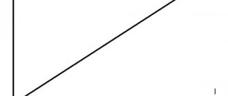
For each of them, a graph is displayed, which is drawn taking into account the angle of rotation of the engine clockwise.
Functional characteristics graphs
Elements that change resistance according to the linear law A are used in voltage dividers. Audio frequency generators (AFGs) include potentiometers in their circuits that use functional characteristic B. Resistors with variable resistance, used in sound reproduction equipment, operate according to law B.
For your information. To obtain the required PC, the components or layer size of the resistive film are changed, and in wire structures, the winding pitch is varied or the frame shape is made with different widths.
The short service life of potentiometers is associated with a violation of the contact density between the slider and the track (wire), which affects the quality of the equipment.
Classification according to operating conditions
According to the features of application and use, types of resistors are divided into groups.
Permanent
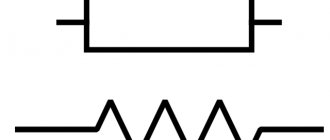
The resistance is constant with an acceptable normalized error and corresponds to the standard. On the electrical diagram they are depicted as a rectangle with sides 10x4 mm. Lead lines are drawn from the center of the narrow side. Next to the image they place the letter “R” with the serial number of the case according to the diagram. The denomination value is indicated here.
The scattering fits inside the rectangle. In imported technical documentation it is often depicted as a zigzag line connecting the terminals.
Variables and tuning
The components of a variable potentiometer are equipped with three or more terminals, and a mechanism for moving a slider - a current collector. The range of change extends from zero to a maximum limited by the set nominal value.
Changing the characteristics of the equipment during operation, such as adjusting the tuner, adjusting the volume level or lighting, is performed by a variable component.
The mechanism for moving the slider ends with a handle that allows for quick adjustments. If the setting is performed during commissioning and should not change daily, trimmers are used. The position of the current collector in them is set with a screwdriver.
Nonlinear
Automation and electronic protection devices actively use semiconductor nonlinear devices, the conductivity of which changes automatically with fluctuations in external environmental factors. The negative temperature coefficient of thermistors increases conductivity as the temperature increases and decreases as the temperature decreases.
A device with a positive TCS is called a posistor. In a photoresistor, the conductivity of the semiconductor layer increases with increasing illumination in the visible, infrared or ultraviolet spectrum.
Varistors are capable of increasing conductivity when the voltage applied to it increases
Magnetoresistors react to a magnetic field, and tensistors record the mechanical force applied to them.
Designation of variable resistors in diagrams
Resistor - what is it and what is it for?
The graphical appearance of the potentiometer is the designation of a rectangle with leads, with a line with an arrow resting on it. In the imported version, instead of a rectangle, there is a zigzag segment representing turns of wire. This designation can be found when calculating the value of R using an online calculator.
Graphic designation on diagrams
Color marking on the resistor housing
When it appeared, I tried to remember the color marking and even memorize it - but nothing good came of it, I still got confused, and the resistor value had to be determined with a tester. Now I don’t remember when, but in one magazine I came across an article on how this whole thing can be avoided. There they talked about a cheat sheet made in the form of a resistor, only instead of colored stripes there are wheels on which the colors involved in designating the resistor values are written. Let's just look at the example shown in the photograph. Let's say we have a resistor with the following colors: green - blue - red. We need to determine its value:
With the first wheel you select the color of the first stripe (green), with the second wheel you select the color of the second stripe (blue), and with the third wheel you select the color of the third stripe (red) - this will be our multiplier. Now we multiply the resulting figure in the first two windows, and we got 56, by the factor obtained in the third window - that’s ten squared or 100. The result is 5600 Ohms or 5.6 kOhms. As you can see, the cheat sheet is very simple to use.
Color marking of domestic resistors
The end result will always be in Ohms, but it is not difficult to convert it to kiloohms or megaohms:
1000 Ohm is 1 kOhm; 10000 Ohm is 10 kOhm; 100000 Ohm is 100 kOhm; 1000 kOhm is 1 megaohm or 1,000,000 Ohms; 10 M is 10000 kOhm or 10000000 Ohm.
To make it, I used cardboard, but you can use any other material that is easy to process. If you use cardboard, then for strength it is advisable to glue it in two layers. I didn’t draw a drawing, but indicated all the dimensions directly on the cheat sheet, because it’s easier for me, and it’s clearer for you. Dimensions are indicated in millimeters.
The next step is to make three wheels. The first two will be the same, and they are marked with the colors of the stripes and the numbers corresponding to each color. The wheel must be divided into ten equal parts, and if you look at the right one, you can see that, for example, brown corresponds to one, and black corresponds to zero.
The sequence is:
- Black – 0;
- Brown – 1;
- Red – 2;
- Orange – 3;
- Yellow – 4;
- Green – 5;
- Blue – 6;
- Purple – 7;
- Gray – 8;
- White – 9.
Resistor with markings
Here the sequence is:
- Black – 1;
- Brown – 10;
- Red – 10 to the power of 2 (100);
- Orange – 10 to the power of 3 (1000);
- Yellow – 10 to the power of 4 (10000);
- Green – 10 to the power of 5 (100000);
- Blue – 10 to the power of 6 (1000000); Purple – 10 to the power of 7 (10000000);
- Gray – 10 to the power of 8 (100000000);
- White – 10 to the power of 9 (1000000000);
- Golden – 10 to the power of -1 (0.1);
- Silver – 10 to the power of -2 (0.01).
Secure the wheels with bolts with a diameter of 3 mm. In any case, if all else fails, the resistance of the resistor can always be measured with a multimeter. If you have any doubts about determining the band of the first number, refer to the tolerance band, which is located on the right side of the resistor. As a rule, the bulk of resistors come with a tolerance of five and ten percent, and these are golden and silver colors.
Resistor in the diagram
Trimmer resistors
Resistor resistance - formula for calculation
The markings for tuning resistors are the same as for variables. Such potentiometers are used for a limited number of rotations of the engine axis. Their use is associated with the adjustment of equipment and electronic circuits in the setup mode, where it is necessary to adjust certain parameters in the required interval and record the resulting resistance value.
Appearance and graphic designation
What is a resistor with variable resistance
Among radioelements, there are parts that can change their main parameter. This is what variable or adjustable resistors are. They differ from constant ones in that their resistance can be smoothly changed from almost zero to a certain value. The change occurs by mechanically moving the slider.
Adjustable or variable resistors - different types and sizes
There are varieties of variable resistors - trimming and adjusting. What is the difference between variable resistors and trimmers? Because the trimmers are designed for a small number of adjustments. For some models, their number can be in the hundreds or tens (for example, for the HP1-9A, you can move the slider no more than 100 times). If you look at the table below, you can see that some SMD trimmer resistors have only 10 adjustment cycles.
Example of characteristics of SMD trimming resistors
For variable resistors this figure is much higher. The number of movements of the regulator can be in the tens and even hundreds of thousands. So it’s clearly not worth using trimming resistors instead of variables.
The main disadvantage of variable resistors is their fragility. The contact between the resistive layer and the brush gradually deteriorates. For acoustic equipment, this can be expressed in ever-increasing noise; when adjusting the frequency in radio receivers, it becomes increasingly difficult to “catch” the desired wavelength, etc.
The animation makes it clear how a variable resistor works and why it fails
Including variable resistors in an electrical circuit
The connection diagram for such resistive elements depends on what they are used for. There are two types of connections to circuits:
- as a rheostat - an adjustable resistor to limit current;
- like a potentiometer - for dividing voltage (divider).
In the first case, the middle and extreme conclusions are taken, in the second - the middle and both extreme ones.
Attention! When the rheostat is turned on, the second free lead is soldered to the middle one to ensure more reliable contact.
Connection methods: rheostat and potentiometer
Any adjustable resistance can be connected as a rheostat or potentiometer. The rheostat changes the current strength in the circuit; for this, a moving contact and one of the outer terminals are connected.
Variable resistor can be used as a rheostat or potentiometer
The potentiometer changes the voltage; when connected, all contacts are activated, thus obtaining a voltage divider.
Determining the type by marking
The marking is adopted in accordance with GOST 11.074.009-78 and has its own interpretation.
The designation of alphanumeric resistor labels (from left to right) is as follows:
- letters RP – variable;
- numbers: 1 – non-wire, 2 – wire or metal foil;
- registration number;
- year of issue;
- FH type;
- nominal resistance value;
- letter of tolerance for deviation from the nominal value.
The number of marks applied depends on the size of the case, but the Rnom value is required.
Decoding the markings on the body
Variable resistors can be of different designs. It is allowed to install several variable resistive elements on one axis. They are used to adjust and adjust many electrical parameters.
Types and features of application
There are a considerable number of variable resistors; they are used to regulate sound, volume, adjust frequency, and adjust light brightness. In general, almost everywhere where settings are changed using sliders or by rotating knobs, these elements are located. But for different tasks, resistors with different patterns of changes or with different numbers of terminals are needed. Let's talk about different types of adjustable resistances.
Variable resistors come in different types
Character of change in resistance
Do not think that when the moving contact moves, the resistance changes linearly. There are such models, but they are used mainly for adjustment or tuning in frequency dividers. Much more often a nonlinear relationship is required. Variable resistors with a nonlinear characteristic are of two types:
- resistance changes according to a logarithmic law;
- according to exponential type (reverse logarithmic).
The nature of resistance changes in variable resistors
In acoustics, nonlinear elements with resistance that have a potential dependence are used; in measuring equipment, they are logarithmic.
Double, triple, quadruple
In players, radios and some other types of household equipment, dual (double) variable resistors are often used. Two resistive plates are hidden in the element body. Externally, they differ from ordinary ones by the presence of two rows of terminals. There are two types:
- With simultaneous change of parameters. Typically used in stereo equipment to simultaneously change the parameters of two channels. Such resistors have parallel runners. By turning or moving the handle, we change the resistance of two resistors at once.
- With separate parameter changes. They are also called coaxial, since the axis of one is inside the axis of the other. If you need to change various parameters (volume and balance) with one knob, this type of resistor is suitable. There is no mechanical connection between the sliders, which allows you to change the resistance independently of each other.
Double adjustable resistor and its designation
Different types of dual variable resistors are designated differently in the diagrams. Since there is a mechanical connection between the sliders and the resistor images are close together on the diagram, interconnected arrows are placed (in the figure above on the left). Belonging to one resistor is indicated through numbering: the two parts are designated as R1.1 and R 1.2. If the designations of the parts of a paired variable resistor are far from each other on the diagram, the connection is indicated using dotted lines (in the figure above on the right). The letter designation is the same.
This is what dual and triple variable resistances look like
A double adjustable resistor without a physical connection between the sliders in the circuits is no different from a regular adjustable one. They are distinguished by a letter designation with two numbers separated by a dot through - like a paired one - R15.1 and R15.2.
A special case of a dual variable resistor - triple, quad, etc. They are not found so often, more and more in acoustic equipment.
Discrete variable resistor
Most often, the change in resistance when turning the knob or moving the slider occurs smoothly. But for some parameters it is necessary to change the parameters in steps. Such variable resistances are called discrete. They are used to stepwise change frequency, volume, and some other parameters.
Discrete variable resistor (with step adjustment) and its designation in the diagram
The design of this type of resistor is different. Essentially, inside there is a set of fixed resistors connected to each of the outputs. When switching, the moving contact jumps from output to output, connecting the resistor currently needed to the circuit. The operating principle can be compared to a multi-position switch.
With switch
We often see such resistors in radios and other devices. With their help, turning the knob turns on the power and then adjusts the volume. It is impossible to distinguish them externally, only by description.
Variable resistor with a switch in one housing: appearance and designation on the diagrams
In the diagrams, variable resistors with a switch are displayed next to the contact group; the fact that this is a single device is displayed using a dotted line that connects the contact group to the body of the variable resistor. On one side - near the resistance image - the dotted line ends with a dot. It shows which terminal the circuit breaks near. When the regulator arm is turned in this direction, the power is turned off.
Video
Coffee capsule Nescafe Dolce Gusto Cappuccino, 3 packs of 16 capsules
1305 ₽ More details
Coffee capsules Nescafe Dolce Gusto Cappuccino, 8 servings (16 capsules)
435 ₽ More details
Rechargeable batteries
Marking
Alphanumeric code
Elements with wire leads are identified by writing on the surface of the housing. The numbers indicate the denomination, and the letters indicate the measurement range. The letters "E" and "R" are for ohms, "K" is for kilohms, and "M" is for megohms.
The letter in the marking acts as a decimal point. For example, the designation 5R8 corresponds to a resistance of 5.8 Ohms, 7K8 means 7.8 kOhms, and M59 equals 590 kOhms.
Color coding
For small components whose labels cannot be read, color marking of resistors using colored stripes has been developed.
A number of colored stripes are shifted to the edge of the case, and the countdown begins from the stripe closest to the edge.
If the marking contains five bars, then the first three will show the resistance value in ohms, the next one determines the multiplier, and the last one indicates the tolerance.
Coding of SMD elements
The photo of surface-mount resistors shows that small sizes require the use of other designation methods. Manufacturers have introduced three basic methods of coding, combining products into groups by size.
Products with a tolerance of 2, 5 and 10%. There is a digital mark on the case, for example 330, 683, 474. The first two numbers indicate the mantissa, and the third acts as an indicator of the power of the number 10. Accordingly, the inscription 330 shows 33*1=33 Ohm, 683 means 68*1000=68 kOhm, 473 respectively 47* 10000=470 kOhm. Some models use the letter "R" as a decimal point.
Models of size 0805 and others with a one-percent tolerance are designated according to a principle similar to the first group: the first three digits are the mantissa, the fourth, the multiplier is a power of the base 10, it is also allowed to use the letter “R”. Set 7430 corresponds to a value of 743 ohms
SMD size 0603 are marked with a combination of two numbers and a letter, which determines the degree of the multiplier: A - zero degree, B - first, C - second, D - third, E - fourth, F - fifth, R - minus the first, S - minus the second , Z – minus the third power. The number indicates the code by which the mantissa is found in the EIA-96 table.
For example, code 75C. 75 in the table corresponds to 590. The letter “C” indicates a multiplier of 100. Accordingly, 590*100=59 kOhm.
Resistor designation
The graphic resistor sign adopted among our compatriots is a rectangle. Abroad, it is depicted as a broken line resembling the letter W. On the diagrams, next to the graphic image, an alphanumeric marking is indicated, which includes the letter R, a number that indicates the number of the element on the diagram, and the resistance value. If a “*” is added to the item position number, this means that the resistance value is approximate. The exact value will have to be selected when setting up the device. Therefore, fixed resistors are not suitable for this application. The rated power dissipation may be indicated within the graphic symbol.
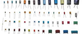
Types of resistors
Manufacturers offer a wide range of resistors, from which you need to select a part that is suitable in design, purpose and price. Let's consider the characteristics of the most common types of these radioelements. Based on the material of the resistive element, products are distinguished into wire, non-wire, and metal foil.
Wire
This is a traditional variety used by our fathers and grandfathers. Conducting wire with high resistivity is made from alloys of copper, nickel, manganese - manganin, constantan, nickel. May become hot during operation.
Non-wire
The design includes: a dielectric base and a coating with a certain resistance. This coating is called resistive; it can be film or volumetric. There are film types:
- Thin film. Their thickness is measured in nanometers. The resistor is applied by vacuum deposition onto a dielectric substrate. The cost of such products is higher than the cost of thick-film analogues. Its advantages: good temperature coefficient of resistance, low parasitic inductance and noise level. They are mainly in demand for microwave devices that require accuracy and stability.
- Thick film. These products have a thickness of tenths of a millimeter. There are varnish, cermet, and based on conductive plastics. These are inexpensive resistors; their deviation from the nominal value is 1-2%.
The resistance of film resistors is adjusted due to the thickness of the coating. The main characteristics of these products: stability, accuracy, wide range of resistance values - from several Ohms to MOhms.
How to determine the type of variable resistor
Equivalent resistance
The general marking of potentiometers and trimming resistors contains a digital and letter designation of the model, which indicates the type, design feature and rating.
The first resistors had the letter “C” at the beginning of the abbreviation, that is, resistance. The second letter “P” stood for variable or tuning. Next came the group number of the current-carrying part. If we were talking about nonlinear models, then the markings began with the letters CH, ST, SF, depending on the material of manufacture. Then came the registration number.
Today the designation RP is used - variable resistor. Then follows the group: wire - 1 and non-wire - 2. At the end there is also a development registration number separated by a dash.
For ease of designation, miniature resistors use their own color palette. If the radio component is too small, markings are applied in the form of 5, 4 or 3 colored rings. The resistance value comes first, then the multiplier, and finally the tolerance.
Resistor color coding
Important! Radio components are produced by many trading companies around the world. The same designations may refer to different parameters. Therefore, models are selected according to the characteristics included in the description.
The general rule for choosing a resistor is to study the official designations on the manufacturer's website. This is the only way to be sure of the required markings.
Tags: . Buy wholesale and retail, delivery throughout Russia TC "Business Lines" and "SDEK" - Moscow (MSK), St. Petersburg (SPB), Ekaterinburg (EKB), Novosibirsk, Nizhny Novgorod, Rostov-on-Don, Voronezh, Chelyabinsk , Kazan, Perm, Krasnodar, Ufa, Krasnoyarsk, Samara, Saratov, Omsk, Yaroslavl, Cheboksary, Stavropol, Ryazan, Izhevsk, Penza, Tula, Tomsk, Irkutsk, Tyumen, Kaliningrad, Kirov, Tolyatti, Bryansk, Volgograd, Novokuznetsk, Tver , Smolensk, Barnaul, Kaluga, Vladivostok, Kemerovo, Lipetsk, Ulyanovsk, Vladimir, Mytishchi, Khabarovsk, Orenburg, Orel, Ivanovo, Kursk, Saransk, Belgorod, Yoshkar-Ola, Murmansk, Tambov, Veliky Novgorod, Lyubertsy, Surgut, Petrozavodsk, Astrakhan, Kostroma, Podolsk, Naberezhnye Chelny, Sochi, Sergiev Posad, Vologda, Arkhangelsk, Kurgan, Stary Oskol, Chita, Serpukhov, Miass, Krasnogorsk, Nizhny Tagil, Korolev, Magnitogorsk, Odintsovo, Volzhsky, Balashikha, Khimki, Makhachkala, Cherepovets, Ramenskoye, Pskov, Velikiye Luki, Ulan-Ude, Pushkino, Novocherkassk, Obninsk, Taganrog, Vyazemsky, Nizhnevartovsk, Severodvinsk, Dubna, Arzamas, Pyatigorsk, Blagoveshchensk, Zhukovsky, Ivanteevka, Volgodonsk, Biysk, Shchelkovo, Fryazino, Berdsk, Abakan, Kolomna , Rybinsk, Murom, Nalchik, Novorossiysk, Syktyvkar, Yuzhno-Sakhalinsk, Kovrov, Dolgoprudny, Domodedovo, Sterlitamak, Angarsk, Chekhov, Ukhta, Kamensk-Uralsky, Kotelniki, Vladikavkaz, Noginsk, Bratsk, Gatchina, Alexandrov, Zheleznogorsk, Zheleznogorsk, Istra , Pavlovo, Petropavlovsk-Kamchatsky, Stupino, Yakutsk, Voskresensk, Dmitrov, Dimitrovgrad, Maloyaroslavets, Sarov, Ozersk, Tuapse, Almetyevsk, Vyborg, Balakovo, Seversk, Aleksin, Magadan, Elektrostal, Armavir, Norilsk, Lobnya, Apatity, Neftekamsk, Glazov , Yeysk, Elektrougli, Dzerzhinsk, Kstovo, Novomoskovsk, Sarapul, Komsomolsk-on-Amur, Orsk, Nizhnekamsk, Nevinnomyssk, Nefteyugansk, Klintsy, Vidnoye, Orekhovo-Zuevo, Engels, Novouralsk, Lytkarino, Berezniki, Kamensk-Shakhtinsky, Safonovo, Novocheboksarsk , Novy Urengoy, Mezhdurechensk, Kirovo-Chepetsk, Yelets, Salavat, Syzran, Sosnovy Bor, Tikhvin, Pokrov, Prokopyevsk, Dzerzhinsky, Zheleznodorozhny, Krasnoarmeysk, Solnechnogorsk, Tchaikovsky, Nakhodka, Vorkuta, Rossosh, Lukhovitsy, Naro-Fominsk, Vyksa, Vsevolozhsk , Revda, Ust-Ilimsk, Belorechensk, Dedovsk, Klin, Reutov, Ruza, Balakhna, Ussuriysk, Bakhchisaray, Rzhev, Sortavala, Krasnoyarsk, Novorilsk
Parameters taken into account when purchasing resistors
When purchasing these parts, consider:
- The most important parameter is resistance, which is determined by regulatory documentation. Its nominal value is indicated on the body of the part. Values up to 999 Ohms are expressed in Ohms, 1000-99000 Ohms - in kOhms, from 1,000,000 Ohms - in MOhms. In addition to resistance, it is necessary to correctly select the accuracy tolerance, which can be in the range of 0.5-10%. When choosing the tolerance value, you should remember: the higher the accuracy, the smaller the operating temperature interval.
- Rated power is the maximum permissible power dissipated on a resistor element, at which the performance characteristics of the resistor are maintained throughout the entire specified operating period. For example, if you bought a 100 Ohm resistor with a tolerance of ±10%, then its actual resistance may be 90-110 Ohms. You can find out the exact resistance of this resistor only by measuring it with an ohmmeter or multimeter.
- Temperature coefficient of resistance. This value characterizes the relative change in the resistance of the part when the temperature increases or decreases by 1°C. TCR for one resistor in different temperature ranges can have different values.
- Electrical strength. Indicates the maximum voltage at which the element can operate without failure throughout its specified service life.