The need to read the electrical network diagram
A specialist can quickly find the required element using the icon. Such knowledge is required in various situations, such as repairing an existing electrical network, laying a new one, or installing electrical equipment. To install a new electric meter, you need to find the old one and replace it. On large objects, drawings are confusing, and you need to understand them in a short time
Quick study of drawings is important in emergency situations
Knowledge of symbols and skills in reading circuit diagrams or simplified single-line variants may be required for every person. Even a simple replacement of electrical wiring will force you to face difficulties without an understanding of basic things. Reading a blueprint helps ensure safety during electrical installation work.
Replacing a meter is a common operation, so knowing the designation of the meter in the diagram is so important
Antimagnetic seals on electric meters and their features
Some consumers are trying to save money on utility bills by “cheating” the magnetic seal on the electric meter. Most often, neodymium magnets are used for this. With their help, the electromechanical counter stops.
For this reason, regulatory authorities install anti-magnetic seals on consumer electricity meters. Outwardly, they resemble a sticker, but its structure is much more complex than it might seem at first glance. Inside the seal there is a sensor that records magnetic changes. When a certain threshold is crossed, the device is triggered. As a result, when the time comes to verify the electricity meter, an employee of the regulatory authorities will be able to determine the presence of outside interference by the appearance of the device.
The sensor itself is a small capsule filled with a substance that reacts sensitively to the presence of a magnetic field. If such an intervention has taken place, the contents spread throughout the capsule. After this, no means can restore it to its original appearance. A completely colored capsule will indicate that an attempt was made to stop the metering device.
Anti-magnetic seal for electric meter
How much does it cost to seal an electricity meter?
Sealing is carried out when it is time to replace the electric meter or there is a need for its repair. All costs for servicing the device are covered by the owner, but installation of the seal is performed free of charge. If repairs or replacement of the electric meter are expected, the price is already included in the cost of these procedures. If they resort to sealing again, in this case the service will need to be paid (from 100 to 500 rubles, depending on the region of residence).
Forcing the owner to pay for the initial installation of a seal after the above maintenance is considered illegal. In such cases, there are several ways to solve the problem:
- Pay the required amount, immediately receive a receipt confirming the fact of payment with the obligatory indication that the assigned amount was taken specifically for installing the seal. This document may become the basis for filing a complaint with higher regulatory authorities that a fee is illegally charged for the provision of a free service.
- File a claim in court.
- Submit an application to the service involved in antimonopoly activities (FAS).
Initial sealing of the meter is free of charge
It is worth noting that for household electricity meters the price for installing a seal is low, so the apartment owner independently decides whether to pay for this service or not.
Anti-magnetic seal on the meter: principle of operation, how to bypass
Companies involved in the production of energy metering devices are constantly improving their products and protecting them from hacking attempts or changing the true readings. However, craftsmen are difficult to stop, and they are constantly looking for ways to circumvent the most advanced mechanisms used by manufacturers. In recent years, to deceive supervisory services, unscrupulous citizens of our state have used very powerful neodymium magnets that can stop any meter.
However, not so long ago, anti-magnetic seal-stickers began to be used to protect water, gas and electrical metering devices. With the advent of new funds, heated discussions began to take place among people who were accustomed to illegally saving on utility bills about how to deal with them. Therefore, in order not to do anything stupid, every homeowner who uses different utility services should know - is it really possible to bypass the protection at home?
What it is
To date, various types of antimagnetic stickers have been developed that visually notify of an attempt to influence an electric meter with a powerful magnetic field. At the beginning of 2011, in the territorial space of the former countries of the Union, such devices began to be installed on meters for metering the consumption of water, gas and light. But the ingenuity of modern man has helped craftsmen find ways to combat some stickers, although there are not so many successful attempts. Services providing the population with energy resources do not sit still and they have developed more complex protection.
What do the markings, numbers and text mean?
An antimagnetic seal is nothing more than a sticker based on a special sealing tape and equipped with a hermetic capsule containing a magnetically sensitive suspension . Microscopic particles contained in the suspension are sensitive to magnetic fields exceeding 100 mT. By changing their original state and spreading inside the capsule, they notify about the impact of the magnet on the electricity consumption monitoring device. The indicator seal is mounted by gluing it to the body of the monitoring meter.
In its normal state, the indicator element has a uniform consistency, shaped like a black dot with a cross-section of up to 2 mm. If such a protective sticker is exposed even briefly with a magnet, the dot changes its structure, spreading over the entire area. In this case, all antimagnets are numbered individually; they cannot be removed from the device body, as this leads to its destruction and the appearance of a corresponding inscription.
Such elements are installed in accordance with the basic sample of an existing act on the sealing of the meter by a representative of the energy inspectorate in the presence of the homeowner. At the same time, it must be explained to the consumer that if the protection on the individual electricity consumption control device is triggered, additional charges for utilities in accordance with the current government decree.
What are the dangers of removing a protective sticker?
Despite the fact that there are rumors among electricity consumers about the fight against anti-magnetic seals, it is not easy to deceive them. The most complex indicator is considered to be a black dot in a sealed capsule, which is triggered by any exposure to a magnetic field. Any attempt to violate the integrity of the protective element will lead to the following consequences:
- distribution of the suspension inside the capsule;
- changing the color of the sticker;
- loss of rigidity or consumption of the control pattern;
- the appearance of a warning notice on the seal.
If a representative of the energy supervision authority checks the damaged sticker, the cunning homeowner will be held administratively liable . A fine will be issued if attempts are made to peel off the anti-magnetic sticker and if the electric meter is exposed to any magnetic field.
How to bypass an anti-magnetic seal - popular methods
Naturally, enterprises supplying energy resources to consumers are trying in every possible way to protect themselves from possible theft of resources, but at the same time trying to save on protective equipment. Sometimes they install elements of dubious quality, which craftsmen are able to bypass. However, if a modern anti-magnetic seal is installed on the meter, then all known methods of bypassing it lead to a negative result .
- There is a misconception that the self-adhesive layer of the sticker can come off the body when heated by a hairdryer . In reality, when heated, except for compromising the integrity of the protection, nothing good will happen.
- Craftsmen went further, deciding that if heat does not help, you need to use cold . However, as with rising temperatures, freezing will damage the sticker and expose fraudulent activity.
- But the most popular is mechanical action . Some experimenters pick at the capsule with sharp objects, without thinking that it is one with the sticker. Other craftsmen resort to disassembling the meter itself. But all attempts lead to failure and, as a consequence, to an administrative fine after an inspector visits the house during the next scheduled inspection.
But still, even despite the failures, scammers never tire of looking for ways to bypass the anti-magnetic seal. Unfortunately for attackers, there are no effective ways to deceive such protection. Therefore, it will not be possible to avoid punishment for atrocities. Although this does not concern conscientious utility payers.
Summing up, we can say with confidence that those who want to change the readings of monitoring devices for consumed energy resources, be it water, light or gas, will sooner or later fail and their cunning plans will be revealed during the next check of metering devices. And in such a situation, they will face appropriate punishment in the form of an administrative fine in a fairly large amount, and in especially severe cases - complete disconnection from public services and even criminal liability.
What is the accuracy class of an electric meter?
For electrical measuring instruments, the international standard provides for several accuracy classes that determine the quality of measurements. In accordance with the class, on the body of the device, a corresponding digital designation is applied, indicating the percentage error that is permissible in measurements, that is, it cannot significantly distort the readings in favor of any of the parties.
What are the accuracy classes?
In accordance with the international measurement system SI, the following main classes are provided for electrical measuring instruments:
- 0,05.
- 0,1.
- 0,2.
- 0,5.
- 1,5.
- 2,5.
The order of the class is inversely proportional to its digital value, that is, the lower the number, the higher the class. To establish the percentage of error or the fact that it exceeds its limits, a verification is carried out - a comparison of the readings of the meter being verified and the reference one.
As the latter, any device with a class one or more levels higher can be used. The most accurate instruments with a class of 0.05 and higher, as a rule, are laboratory samples not used in industry, for household consumers; such high accuracy is also not necessary.
Electric meter
The measurement of any physical quantity always occurs with errors, and in order for the calculation based on the measurement to be the most accurate, measuring instruments of the appropriate accuracy class are used. Electrical measurements, in particular, the consumption of electricity, are no exception. Assignment to any of the accuracy classes indicates the range within which the actual measurement value can fluctuate, that is, this is the percentage ratio of the accuracy class to the maximum value on the scale. Despite the fact that an electric meter is considered exclusively a household appliance, it can have different classes and be used not only by household subscribers.
Symbols on the dashboard of an electric meter
Counter type.
Trademark and logo of the manufacturer.
Instrument accuracy class.
Mains voltage.
Rated current - the current at which the characteristics of the meter are measured.
Maximum permissible current.
AC frequency.
Number of disk revolutions per 1 kWh of consumed electricity.
Direction of disk rotation.
Serial number of the device and year of its manufacture.
A sign indicating that the device has a quality certificate.
A sign indicating that the device has a certificate and is included in the State Register of Measuring Instruments.
Designation of the support disc made of two stones used in the lower bearing.
Symbol for double insulation, which increases the safety of the device.
A sign indicating that the meter is single-phase.
A counting mechanism showing the number of full kilowatt-hours with tenths (after the decimal point).
Features of installing meters
The meters must be directly connected and have a seal with a state verifier's stamp that is no older than at the time of installation: three-phase - 12 months, single-phase - 2 years. In apartment-type residential buildings; One single-phase meter should be installed per apartment.
In residential buildings owned by citizens | personal property, it is allowed to install three-phase meters with a special permit from the energy supply organization, while a single-phase meter is installed for the lighting load.
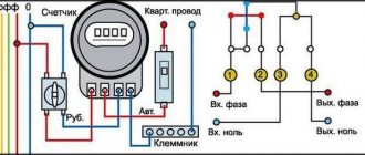
The meters are connected to the network in accordance with the accepted diagram (on the inside of the cover 1 of the terminal box), observing the phase sequence. In 220 V networks, which require long-term operation in the mode of uneven phase loads, three-phase four-wire meters should be used.
To measure and account for the amount of electricity in single-phase networks with a voltage of 220 V, single-phase meters of the SO-I446, SO-5U, etc. types are used; in three-phase and four-wire networks, meters of the SAZ and SA4 series are used, as well as reactive energy meters of the SR series. Currently, the most common meters in homes are the SO-I446 type. They are being replaced by electronic meters.
Meter panel
The following is written on the meter plate:
designation, for example, for apartment meters SO-2, SO-5, etc., where the letters SO are a single-phase meter;
name of the electricity metering unit, for example, kilowatt-hours;
rated voltage, for example, 220V, current, for example, 5 A, frequency - 50 Hz;
maximum current at which there is no metering error; leaves the accuracy class (see below). Current values are written on a line.
Example. The label says 5-15 A. This means that 5 A is the nominal current, and 15 A is the maximum current. In old meters, the maximum current value is indicated in parentheses, for example, 5 (15) A. If the maximum current is not specified, then the meter allows double load compared to the rated load.
accuracy class - Arabic numerals in a circle, for example, 2.5;
meter gear ratio, for example 1 kWh = 1250 disk revolutions. To make it easier to count the number of revolutions, there is a mark on the edge of the disk. The arrow at the disk slot indicates the direction of rotation (from left to right), in which the readings of the counting mechanism increase;
meter number and year of manufacture.
The meter switching circuit is located on the back of the box, with clamps.
Electronic electricity meters (hereinafter referred to as EC) have the best metrological characteristics. The operation of the ES is based on the use of a static power converter to direct voltage. In this case, double modulation is used with the conversion of voltage into the frequency of electrical pulses and subsequent integration. The block diagram of an AC active energy ES contains a power-to-voltage converter (PPC), a voltage-to-frequency converter (VFC) and a pulse counter (PL). The PPN contains pulse width modulation (PWM) and pulse amplitude modulation (APM) blocks. The input of the PWM block receives a voltage proportional to the load current In, and the input of the AIM block receives the voltage across the load Un. Using a PWM circuit, voltage U1 is converted into a sequence of rectangular pulses of variable duration. Figure 1 - Electronic AC energy meter. The circuit is functional. With a change in the value of U1, the ratio of the difference in the durations of the pulses Ti and the intervals between them Tp to their sum changes, i.e. where k is a constant coefficient; ΔT = Te - Tp - difference in pulse duration; T = Te + Tn - pulse repetition period. Since the amplitude of the pulses in the AIM circuit changes proportionally to the voltage on the load, and their duration is functionally related to the load current, the input signals are multiplied in the AIM block. The average voltage value U3 at the output of the AIM circuit is proportional to the active power Рн. With the help of a low-voltage frequency converter, the voltage U3 is converted into a pulse frequency, which is thus proportional to the power Рн. The output pulses of the low-voltage frequency converter are counted by a pulse counter LI, i.e. thereby achieving their integration. Consequently, LI readings are proportional to active energy W. Electronic active energy meters of alternating current, commercially produced, have an accuracy class of 0.5.
| Taking meter readings |
| To determine the electricity consumption taken into account by a universal transformer meter for any period of time, it is necessary to multiply the difference between the readings taken at the beginning and the end of this period by a conversion factor. The conversion factor kP is determined by the formula (24) where KI is the transformation ratio of current transformers; КU is the voltage transformer transformation ratio. According to GOST requirements, the removable panels of these meters must contain the inscriptions “Current Transformer”, “Voltage Transformer”, “K...”, next to which the subscriber must indicate the transformation coefficients and the conversion factor. Example 1. Determine electricity consumption for a month. SAZU counter readings - I670, 1.05 0 hours 00 minutes - 2438.1; 1.06 0 hours 00 minutes - 2462.8. The meter is connected through current transformers with KI 150/5 and voltage transformer KU = 6000/100. Conversion factor Reading difference 2462.8 - 2438.1 = 24.7. Electricity consumption per month Wa = 24.7 1800 = 44460 kW * h Conversion factor of a transformer meter, in which the transformation factors indicated on the meter plate coincide with the actual ones and are equal to the decimal coefficient. This coefficient (usually 10 or 100) is placed on the counter to the right of the last digit of the counting device. If the transformation ratios of the installed measuring transformers differ from those indicated on the meter plate, then the conversion factor is determined by the formula: (25) where are the transformation ratios of the current transformers and voltage transformers to which the meter is connected; - coefficients of current and voltage transformers indicated on the meter panel. At the first opportunity in such cases, transformer meters must be replaced with universal transformer meters. Example 2. The meter label indicates: current transformer with KI = 100/5; voltage transformer with KU =3000/100. The meter is connected to current transformers with KI = 200/5 and to a voltage transformer with KU = 6000/100. Then the conversion factor according to (25) Based on the readings of the active and reactive energy meters, it is possible to determine the weighted average tg of the connection using the formula (26) where Wa is the amount of energy recorded by the active energy meter for a given period of time; WP is the amount of energy recorded by the reactive energy meter for the same period. Example 3. During the day, the active energy meter took into account the consumption of 18,000 kW*h, the reactive energy meter of 9,000 kvar*h. Then, according to (26) If both meters have the same gear ratio and the same conversion factor, then this allows us to determine the value of tg at a given moment. To do this, it is necessary to simultaneously count the number of revolutions nP of the reactive energy meter and the number of revolutions na of the active energy meter in a short period of time (30 - 60 s), then (27) In the absence of a reactive energy meter, the value tg can be determined from one active energy meter. To do this, it is necessary to briefly, for 30 - 60 s, remove the voltage of phase A from the meter and count the number of revolutions of the disk. Then the voltage circuit of phase A is restored, the voltage is removed from phase C and the number of disk revolutions for the same time is counted. The load should be close to constant. If we designate n1 as the larger number of revolutions, and n2 as the smaller number, then tg can be determined by the formula (28) The number n2 is taken with a negative sign when the disk rotates in the opposite direction, which occurs if tg >l.73. Example 4. In 60 s, the number of disk revolutions when phase A is turned off is n1 = 33, and when phase C is turned off, n2 = 20, then according to (28) Using the active energy meter, in the presence of a stopwatch, the active power of the connection load at the moment can be determined. To do this, you need to count the number of revolutions of the disk over a period of time of 30-60 s. The load should not change significantly. Then the load power P, kW, is determined by the formula (29) where KI and KU are the transformation ratios of current and voltage transformers; n is the counted number of disk revolutions; t—time, s; N is the gear ratio of the meter. Example 5. A meter with a gear ratio of 1 kW*h = 2500 disk revolutions is connected to current transformers with KI = 300/5 and to a voltage transformer with KU = 6000/100. The counter disk made 15 revolutions in 58 s. The active power of the connection load is equal to (29) |
Control questions:
1.List the main components of the meter
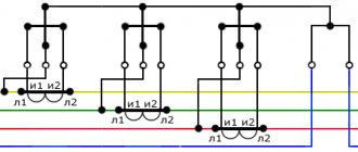
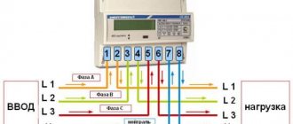
2. Provide a circuit diagram for connecting the meter
3. The meter scale says: 1 kW*hour – 2500 rpm. Calculate the nominal constant of the meter.
4. The current in the circuit is 2.5 A, voltage 220 V. How many revolutions will the counter make in 5 minutes?
Why does “self-propelling” occur in meters?
PRACTICAL LESSON
Laboratory work 9 “Guidelines for performing laboratory work on electrical measurements” is being carried out
FORMULATION OF THE REPORT
1. Answers to questions under paragraph 1
2.Filling out measurement tables and performing calculations
3. Conclusions
Protection
Students answer the teacher's questions and submit a completed report on their work.
Counter type.
Trademark and logo of the manufacturer.
Instrument accuracy class.
Mains voltage.
Rated current - the current at which the characteristics of the meter are measured.
Maximum permissible current.
AC frequency.
Number of disk revolutions per 1 kWh of consumed electricity.
Direction of disk rotation.
Serial number of the device and year of its manufacture.
A sign indicating that the device has a quality certificate.
A sign indicating that the device has a certificate and is included in the State Register of Measuring Instruments.
Designation of the support disc made of two stones used in the lower bearing.
Symbol for double insulation, which increases the safety of the device.
A sign indicating that the meter is single-phase.
A counting mechanism showing the number of full kilowatt-hours with tenths (after the decimal point).
Features of installing meters
The meters must be directly connected and have a seal with a state verifier's stamp that is no older than at the time of installation: three-phase - 12 months, single-phase - 2 years. In apartment-type residential buildings; One single-phase meter should be installed per apartment.
In residential buildings owned by citizens | personal property, it is allowed to install three-phase meters with a special permit from the energy supply organization, while a single-phase meter is installed for the lighting load.
The meters are connected to the network in accordance with the accepted diagram (on the inside of the cover 1 of the terminal box), observing the phase sequence. In 220 V networks, which require long-term operation in the mode of uneven phase loads, three-phase four-wire meters should be used.
To measure and account for the amount of electricity in single-phase networks with a voltage of 220 V, single-phase meters of the SO-I446, SO-5U, etc. types are used; in three-phase and four-wire networks, meters of the SAZ and SA4 series are used, as well as reactive energy meters of the SR series. Currently, the most common meters in homes are the SO-I446 type. They are being replaced by electronic meters.
Meter panel
The following is written on the meter plate:
designation, for example, for apartment meters SO-2, SO-5, etc., where the letters SO are a single-phase meter;
name of the electricity metering unit, for example, kilowatt-hours;
rated voltage, for example, 220V, current, for example, 5 A, frequency - 50 Hz;
maximum current at which there is no metering error; leaves the accuracy class (see below). Current values are written on a line.
Example. The label says 5-15 A. This means that 5 A is the nominal current, and 15 A is the maximum current. In old meters, the maximum current value is indicated in parentheses, for example, 5 (15) A. If the maximum current is not specified, then the meter allows double load compared to the rated load.
accuracy class - Arabic numerals in a circle, for example, 2.5;
meter gear ratio, for example 1 kWh = 1250 disk revolutions. To make it easier to count the number of revolutions, there is a mark on the edge of the disk. The arrow at the disk slot indicates the direction of rotation (from left to right), in which the readings of the counting mechanism increase;
meter number and year of manufacture.
The meter switching circuit is located on the back of the box, with clamps.
Electronic electricity meters (hereinafter referred to as EC) have the best metrological characteristics. The operation of the ES is based on the use of a static power converter to direct voltage. In this case, double modulation is used with the conversion of voltage into the frequency of electrical pulses and subsequent integration. The block diagram of an AC active energy ES contains a power-to-voltage converter (PPC), a voltage-to-frequency converter (VFC) and a pulse counter (PL). The PPN contains pulse width modulation (PWM) and pulse amplitude modulation (APM) blocks. The input of the PWM block receives a voltage proportional to the load current In, and the input of the AIM block receives the voltage across the load Un. Using a PWM circuit, voltage U1 is converted into a sequence of rectangular pulses of variable duration. Figure 1 - Electronic AC energy meter. The circuit is functional. With a change in the value of U1, the ratio of the difference in the durations of the pulses Ti and the intervals between them Tp to their sum changes, i.e. where k is a constant coefficient; ΔT = Te - Tp - difference in pulse duration; T = Te + Tn - pulse repetition period. Since the amplitude of the pulses in the AIM circuit changes proportionally to the voltage on the load, and their duration is functionally related to the load current, the input signals are multiplied in the AIM block. The average voltage value U3 at the output of the AIM circuit is proportional to the active power Рн. With the help of a low-voltage frequency converter, the voltage U3 is converted into a pulse frequency, which is thus proportional to the power Рн. The output pulses of the low-voltage frequency converter are counted by a pulse counter LI, i.e. thereby achieving their integration. Consequently, LI readings are proportional to active energy W. Electronic active energy meters of alternating current, commercially produced, have an accuracy class of 0.5.
| Taking meter readings |
| To determine the electricity consumption taken into account by a universal transformer meter for any period of time, it is necessary to multiply the difference between the readings taken at the beginning and the end of this period by a conversion factor. The conversion factor kP is determined by the formula (24) where KI is the transformation ratio of current transformers; КU is the voltage transformer transformation ratio. According to GOST requirements, the removable panels of these meters must contain the inscriptions “Current Transformer”, “Voltage Transformer”, “K...”, next to which the subscriber must indicate the transformation coefficients and the conversion factor. Example 1. Determine electricity consumption for a month. SAZU counter readings - I670, 1.05 0 hours 00 minutes - 2438.1; 1.06 0 hours 00 minutes - 2462.8. The meter is connected through current transformers with KI 150/5 and voltage transformer KU = 6000/100. Conversion factor Reading difference 2462.8 - 2438.1 = 24.7. Electricity consumption per month Wa = 24.7 1800 = 44460 kW * h Conversion factor of a transformer meter, in which the transformation factors indicated on the meter plate coincide with the actual ones and are equal to the decimal coefficient. This coefficient (usually 10 or 100) is placed on the counter to the right of the last digit of the counting device. If the transformation ratios of the installed measuring transformers differ from those indicated on the meter plate, then the conversion factor is determined by the formula: (25) where are the transformation ratios of the current transformers and voltage transformers to which the meter is connected; - coefficients of current and voltage transformers indicated on the meter panel. At the first opportunity in such cases, transformer meters must be replaced with universal transformer meters. Example 2. The meter label indicates: current transformer with KI = 100/5; voltage transformer with KU =3000/100. The meter is connected to current transformers with KI = 200/5 and to a voltage transformer with KU = 6000/100. Then the conversion factor according to (25) Based on the readings of the active and reactive energy meters, it is possible to determine the weighted average tg of the connection using the formula (26) where Wa is the amount of energy recorded by the active energy meter for a given period of time; WP is the amount of energy recorded by the reactive energy meter for the same period. Example 3. During the day, the active energy meter took into account the consumption of 18,000 kW*h, the reactive energy meter of 9,000 kvar*h. Then, according to (26) If both meters have the same gear ratio and the same conversion factor, then this allows us to determine the value of tg at a given moment. To do this, it is necessary to simultaneously count the number of revolutions nP of the reactive energy meter and the number of revolutions na of the active energy meter in a short period of time (30 - 60 s), then (27) In the absence of a reactive energy meter, the value tg can be determined from one active energy meter. To do this, it is necessary to briefly, for 30 - 60 s, remove the voltage of phase A from the meter and count the number of revolutions of the disk. Then the voltage circuit of phase A is restored, the voltage is removed from phase C and the number of disk revolutions for the same time is counted. The load should be close to constant. If we designate n1 as the larger number of revolutions, and n2 as the smaller number, then tg can be determined by the formula (28) The number n2 is taken with a negative sign when the disk rotates in the opposite direction, which occurs if tg >l.73. Example 4. In 60 s, the number of disk revolutions when phase A is turned off is n1 = 33, and when phase C is turned off, n2 = 20, then according to (28) Using the active energy meter, in the presence of a stopwatch, the active power of the connection load at the moment can be determined. To do this, you need to count the number of revolutions of the disk over a period of time of 30-60 s. The load should not change significantly. Then the load power P, kW, is determined by the formula (29) where KI and KU are the transformation ratios of current and voltage transformers; n is the counted number of disk revolutions; t—time, s; N is the gear ratio of the meter. Example 5. A meter with a gear ratio of 1 kW*h = 2500 disk revolutions is connected to current transformers with KI = 300/5 and to a voltage transformer with KU = 6000/100. The counter disk made 15 revolutions in 58 s. The active power of the connection load is equal to (29) |
Control questions:
1.List the main components of the meter
2. Provide a circuit diagram for connecting the meter
3. The meter scale says: 1 kW*hour – 2500 rpm. Calculate the nominal constant of the meter.
4. The current in the circuit is 2.5 A, voltage 220 V. How many revolutions will the counter make in 5 minutes?
Why does “self-propelling” occur in meters?
PRACTICAL LESSON
Laboratory work 9 “Guidelines for performing laboratory work on electrical measurements” is being carried out
FORMULATION OF THE REPORT
1. Answers to questions under paragraph 1
2.Filling out measurement tables and performing calculations
3. Conclusions
Protection
Students answer the teacher's questions and submit a completed report on their work.
Letter designations in electrical diagrams
We have already discussed a similar article: decoding cables and wires. If you have read this article, it will be easier for you to understand all the letter symbols. According to GOST 7624-54, the letter designation of elements on electrical circuits looks like this:
- KV – limit switch.
- PV – travel switch.
- DO – cooling pump motor.
- DP – feed motor.
- DS – spindle motor.
- DBH is a high-speed engine.
- DG is the main engine.
- CC – command controller.
- KU – control button.
- Voltage, power, time, index, current relay, respectively - RT, RN, RM, RS, RV, RP, RU, RG, RTV.
Radio technical elements on electronic circuits are designated as follows.
So we have figured out what electrical symbols exist on the circuits, watch this interesting video, it will help you understand some of the features.
Marking examples
With the invention of electronic metering devices, a large number of manufacturers of these products appeared. There was no unified system by which the labeling of electricity meters could be determined. Each manufacturer uses its own product designation.
Let's consider what markings are used by the manufacturer producing the Mercury 230 electric meter. In addition to the name itself, the marking of the electric meter may contain symbols, the explanation of which is given below.
- Type of measured energy (A – active, R – reactive, AR – both types).
- Marking (T) indicates the presence of an internal rater.
- The number 2 means that electrical metering is carried out in two directions.
- P – there is an event log (the facts of disconnection and opening of the meter are recorded).
- Q – power quality control (voltage, frequency, harmonic distortion).
- C – presence of a CAN interface for communication with external devices.
- I – infrared port is installed. The device is typically used for remote readings.
- G – built-in GSM modem. Such an electric meter is capable of independently transmitting readings and other information via a cellular communication channel.
- L – PLC modem. This device uses low-voltage electrical networks to transmit information.
- M – modified PLC modem.
- OS – the design contains a reporting device.
- USPD - the meter contains a device for collecting and transmitting data. Used in automated accounting systems - ASKUE, ASTUE.
- B – a backlit indicator is used.
- S – interface is equipped with internal power supply.
- D – the electric meter is equipped with backup power.
- N – sealing is performed using an electronic seal, which is an autonomous microprocessor device equipped with memory. An electronic seal records the fact that the meter has been opened and can independently transmit a signal.
- O – the device has a built-in load control relay. This function allows you to turn off the load either manually, using a button, or by programming the shutdown when the set consumption limits are reached.
- K – ability to control external devices to disconnect the load.
We also provide for your attention a transcript of another popular electricity meter from the Energomera company - TsE6803V:
Well, maybe someone will find the markings of the GAMMA 1 multi-tariff electricity meter useful:
Now you know what the markings of electricity meters look like and their interpretation. We hope that the information provided was useful to you and now you can determine the characteristics of the meter yourself based on the symbols located on the front panel of the device!
We also recommend reading:
- How to mark wires in an electrical panel
- Characteristics of the electricity meter Mercury 201
- Decoding the markings of wires and cables
Published: 04/28/2017 Updated: 11/04/2017
Procedure for studying drawings
How to read electrical diagrams correctly and understand the information presented on the drawing? It is enough to be able to navigate the graphical symbols of GOST; this is the basis of each developed project.
First, determine the type of drawing. According to GOST 2.702-75, each graphic document has an individual code. All electrical drawings have the letter “E” and a corresponding digital value from 0 to 7. The electrical circuit diagram corresponds to the code “E3”.
Reading the circuit diagram:
Visually familiarize yourself with the presented drawing, pay attention to the specified notes and technical requirements. Find on the schematic diagram all the components indicated in the list of the document; Determine the power source of the system and the type of current (single-phase, three-phase); Find the main components and determine their power source; Familiarize yourself with protection elements and devices; Study the management method indicated on the document, its tasks and algorithm of actions. Understand the sequence of actions of the device when starting, stopping, short circuit; Analyze the operation of each section of the circuit, determine the main components, auxiliary elements, study the technical documentation of the listed parts; Based on the studied document data, draw a conclusion about the processes occurring in each link of the circuit presented in the drawing. Knowing the sequence of actions, alphabetic symbols, you can read any electrical circuit
Knowing the sequence of actions, alphabetic symbols, you can read any electrical circuit.
Designation of electrical elements on diagrams
To understand what exactly is shown on a diagram or drawing, you need to know the decoding of the icons that are on it.
This recognition is also called blueprint reading. And to make this task easier, almost all elements have their own symbols. Almost, because the standards have not been updated for a long time and some elements are drawn by everyone as best they can.
note
But, for the most part, symbols in electrical diagrams are in regulatory documents.
Symbols in electrical circuits: lamps, transformers, measuring instruments, basic components
Normative base
There are about a dozen varieties of electrical circuits, the number of different elements that can be found there is in the tens, if not hundreds. To make it easier to recognize these elements, uniform symbols have been introduced in electrical circuits. All rules are prescribed in GOSTs. There are many of these standards, but the main information is in the following standards:
Regulatory documents that specify graphic designations of the element base of electrical circuits
Studying GOSTs is useful, but it requires time, which not everyone has enough of. Therefore, in the article we will present symbols in electrical circuits - the basic element base for creating drawings and wiring diagrams, circuit diagrams of devices.
Some experts, after carefully looking at the diagram, can say what it is and how it works. Some can even immediately indicate possible problems that may arise during operation.
It’s simple - they know the circuit design and element base well, and are also well versed in the symbols of circuit elements.
This skill takes years to develop, but for dummies, it’s important to remember the most common ones first.
Designation of LED, Zener diode, transistor (various types)
Electrical panels, cabinets, boxes
On the power supply diagrams of a house or apartment there will definitely be a designation of an electrical panel or cabinet. In apartments, the terminal device is mainly installed there, since the wiring does not go further.
Houses can be designed to install an electrical branch cabinet - if there is a route from it to illuminate other buildings located at some distance from the house - a bathhouse, a summer kitchen, a guest house.
These other symbols are in the next picture.
Designation of electrical elements on diagrams: cabinets, panels, consoles
If we talk about images of the “filling” of electrical panels, it is also standardized. There are symbols for RCDs, circuit breakers, buttons, current and voltage transformers and some other elements. They are shown in the following table (the table has two pages, scroll by clicking on the word “Next”)
NumberNameImage on the diagram
| 1 | Circuit breaker (automatic) |
| 2 | Switch (load switch) |
| 3 | Thermal relay (overheat protection) |
| 4 | RCD (residual current device) |
| 5 | Differential automatic (difavtomat) |
| 6 | Fuse |
| 7 | Switch (switch) with fuse |
| 8 | Circuit breaker with built-in thermal relay (for motor protection) |
| 9 | Current transformer |
| 10 | Voltage transformer |
| 11 | Electricity meter |
| 12 | A frequency converter |
| 13 | Button with automatic opening of contacts after pressing |
| 14 | Button with contact opening when pressed again |
| 15 | A button with a special switch to turn off (stop, for example) |
Element base for electrical wiring diagrams
When drawing up or reading a diagram, the designations of wires, terminals, grounding, zero, etc. are also useful. This is what a novice electrician simply needs, or in order to understand what is shown in the drawing and in what sequence its elements are connected.
NumberNameDesignation of electrical elements on the diagrams
| 1 | Phase conductor |
| 2 | Neutral (zero working) N |
| 3 | Protective conductor (“ground”) PE |
| 4 | Combined protective and neutral conductors PEN |
| 5 | Electrical communication line, buses |
| 6 | Bus (if it needs to be allocated) |
| 7 | Busbar taps (made by soldering) |
An example of the use of the above graphic images is in the following diagram. Thanks to the letter designations, everything is clear even without graphics, but duplication of information in diagrams has never been superfluous.
An example of a power supply diagram and a graphic representation of the wires on it
Picture of sockets
The wiring diagram should indicate the installation locations of sockets and switches.
There are many types of sockets - 220 V, 380 V, hidden and open installation types, with a different number of “seats”, waterproof, etc. To give a designation for each is too long and unnecessary.
It is important to remember how the main groups are depicted, and the number of contact groups is determined by the strokes.
Designation of sockets in the drawings
Sockets for a single-phase 220 V network are indicated on the diagrams in the form of a semicircle with one or more segments sticking up. The number of segments is the number of sockets on one body (illustration in the photo below). If only one plug can be plugged into the socket, one segment is drawn upward, if two, two, etc.
Symbols for sockets in electrical diagrams
If you look at the images closely, notice that the symbolic image that is on the right does not have a horizontal line that separates the two parts of the icon.
This line indicates that the socket is concealed, that is, it is necessary to make a hole in the wall for it, install a socket box, etc. The option on the right is for open mounting.
A non-conductive substrate is attached to the wall, and the socket itself is on it.
Important
Also note that the bottom of the left diagram has a vertical line through it. This indicates the presence of a protective contact to which grounding is connected. Installing sockets with grounding is mandatory when turning on complex household appliances such as a washing machine, dishwasher, oven, etc.
Graphic
As for the graphic designation of all elements used in the diagram, we will provide this overview in the form of tables in which the products will be grouped by purpose.
In the first table you can see how electrical boxes, panels, cabinets and consoles are marked on electrical circuits:
The next thing you should know is the symbol for power sockets and switches (including walk-through ones) on single-line diagrams of apartments and private houses:
As for lighting elements, lamps and fixtures according to GOST are indicated as follows:
In more complex circuits where electric motors are used, elements such as:
It is also useful to know how transformers and chokes are graphically indicated on circuit diagrams:
Electrical measuring instruments according to GOST have the following graphic designation on the drawings:
By the way, here is a table useful for novice electricians, which shows what the ground loop looks like on a wiring plan, as well as the power line itself:
In addition, in the diagrams you can see a wavy or straight line, “+” and “-”, which indicate the type of current, voltage and pulse shape:
In more complex automation schemes, you may encounter incomprehensible graphic symbols, such as contact connections. Remember how these devices are designated on electrical diagrams:
In addition, you should be aware of what radio elements look like on projects (diodes, resistors, transistors, etc.):
That's all the conventional graphic symbols in the electrical circuits of power circuits and lighting. As you have already seen for yourself, there are quite a lot of components and remembering how each is designated is possible only with experience. Therefore, we recommend that you save all these tables so that when reading the wiring plan for a house or apartment, you can immediately determine what kind of circuit element is located in a certain place.
Interesting video on the topic:
We have already told you how to decipher the markings of wires and cables. Single-line electrical circuits also have their own letters, which make it clear what is included in the network. So, according to GOST 7624-55, the letter designation of elements on electrical circuits is as follows:
- Relays for current, voltage, power, resistance, time, intermediate, indicating, gas and time-delayed, respectively - RT, RN, RM, RS, RV, RP, RU, RG, RTV.
- KU – control button.
- KV – limit switch.
- CC – command controller.
- PV – travel switch.
- DG is the main engine.
- DO – cooling pump motor.
- DBH is a high-speed engine.
- DP – feed motor.
- DS – spindle motor.
In addition, in the domestic marking of elements of radio engineering and electrical circuits, the following letter designations are distinguished:
This completes a brief overview of symbols in electrical circuits. We hope that now you know how sockets, switches, lamps and other circuit elements are indicated on drawings and plans of residential premises.
Home » Electrical » Designation of electrical elements on diagrams
GOST 25372-95 Symbols for AC electrical energy meters
GOST
25372-95 (IEC 387-92)
INTERSTATE STANDARD
SYMBOLS FOR AC ELECTRIC ENERGY METERS
INTERSTATE COUNCIL FOR STANDARDIZATION, METROLOGY AND CERTIFICATION
Minsk
Preface
1. DEVELOPED by the All-Russian Research Institute of Standardization and Certification in Mechanical Engineering (VNIINMASH)
INTRODUCED by Gosstandart of the Russian Federation
2. ADOPTED by the Interstate Council for Standardization, Metrology and Certification (Protocol No. 8 of October 12, 1995)
The following voted for adoption:
| State name | Name of the national standardization body |
| The Republic of Azerbaijan | Azgosstandart |
| Republic of Belarus | State Standard of Belarus |
| The Republic of Kazakhstan | Gosstandart of the Republic of Kazakhstan |
| The Republic of Moldova | Moldovastandard |
| Russian Federation | Gosstandart of Russia |
| The Republic of Tajikistan | Tajikgosstandart |
| Turkmenistan | Main State Inspectorate of Turkmenistan |
| Ukraine | State Standard of Ukraine |
3. This standard contains the full authentic text of the international standard IEC 387-92 “Conventions for alternating current electricity meters” with additional requirements reflecting the needs of the country’s economy
4. By Decree of the Committee of the Russian Federation on Standardization, Metrology and Certification dated March 27, 1996 No. 212, the state standard GOST 25372-95 (IEC 387-92) was put into effect directly as the state standard of the Russian Federation on July 1, 1996.
5. INSTEAD GOST 25372-82
6. REPUBLICATION. March 2005
Content
| 1 area of use 2. Normative references 3. Terms and definitions 4. Symbols for measuring elements of meters 5. Symbols of units of physical quantities used for meters 6. Marking of the measured value 7. Symbols of accuracy class, meter constant, meter gear ratio and insulation protection class 8. Symbols for meters connected via instrument transformers 9. Symbols of charging devices 10. Symbols for auxiliary devices 11. Symbols for parts of the suspension of the movable element of the meter 12. Warning symbols APPENDIX A (recommended) SYMBOLS FOR SIGNAL HOLES |
INTERSTATE STANDARD
| SYMBOLS FOR AC ELECTRIC ENERGY METERS Symbols for alternating-current electricity meters |
Date of introduction 1996-07-01
This standard applies to letter and graphic symbols for alternating current electric energy meters (hereinafter referred to as meters) and their auxiliary devices, regardless of the measuring elements of induction or static meters.
Model electricity meters and their auxiliary devices can be marked with symbols that differ from those established in this standard.
The symbols specified in this standard may be printed on the shield, dial, external labels or auxiliary devices of meters.
All requirements of this standard, except 6.6 of Table 3 and Appendix A, are mandatory.
Additional requirements for symbols for electricity meters, reflecting the needs of the country's economy, are highlighted in italics in the standard.
This standard uses references to the following standards:
GOST 8.417-2002 State system for ensuring the uniformity of measurements. Units of quantities
GOST 23217-78 Analogue electrical measuring instruments with direct reading. Applied symbols
This standard uses the following terms:
3.1. induction meter for electrical energy:
An electric energy meter, the operation of which is based on the rotation of the disk of an induction measuring mechanism.
3.2. static electricity meter:
An electrical energy meter in which current and voltage are applied to solid-state (electronic) elements to produce output pulses whose number and frequency are proportional to the energy and power, respectively.
3.3. watt hour meter:
An instrument designed to measure active energy by integrating active power over time.
3.4. var-hour counter:
An instrument designed to measure reactive energy by integrating reactive power over time.
3.5. volt-amp hour meter:
An instrument designed to measure apparent energy by integrating the apparent power over time.
3.6. multi-tariff electric energy meter:
An electric energy meter equipped with a set of counting mechanisms, each of which operates at set time intervals corresponding to different tariffs.
3.7. excess electrical energy meter:
Electric energy meter designed to measure excess electrical energy during the time when the power value exceeds a predetermined value.
3.8. maximum indicator (for counter):
A device attached to a meter to indicate the highest value of average power used during successive equal intervals of time.
3.9. maximum counter:
Counter equipped with a maximum indicator.
3.10. bidirectional counter:
A meter designed to measure electrical energy in both directions.
3.11. Memory device:
An element designed to store digital information.
3.12. display:
A device that displays information from storage device(s).
3.13. counting mechanism:
An electromechanical or electronic device containing both a storage device and a display that stores and displays information.
If the meter is used with current and (or) voltage transformers, then the counting mechanism can be primary, secondary and mixed.
One display can be used with several electronic storage devices to form multi-tariff counting mechanisms.
3.14. primary counting mechanism:
The counting mechanism of a meter connected through measuring transformers, which takes into account the transformation ratios of all transformers (voltage and current transformers), but does not take into account the transformation ratios of both at the same time.
NOTE The energy value is obtained by direct reading of the counting mechanism.
3.15. mixed counting mechanism:
The counting mechanism of a meter connected through instrument transformers, which takes into account the transformation ratio(s) of the current or voltage instrument transformer(s), but does not take into account the transformation ratios of both simultaneously.
Note - The energy value is obtained by multiplying the readings of the counting mechanism by the appropriate coefficient.
3.16. secondary counting mechanism:
The counting mechanism of a meter connected through instrument transformers, which does not take into account the transformation ratio(s).
Note - The energy value is obtained by multiplying the reading of the counting mechanism by the appropriate coefficient.
3.17. meter panel:
A plate that is easily accessible for reading, fixed inside or on the outer surface of the meter, on which the values corresponding to the conditions of use of the meter are indicated, and on which symbols can also be applied.
3.18. clock face:
Part of the reading device on which the scale or scales and symbols characterizing the device are applied
Note - In some cases the shield and dial may be combined.
3.19. counter constant:
A coefficient expressing the ratio of the counted energy to the number of revolutions of the counter disk (rotor) or to the number of output pulses.
The counter constant is expressed in units of counted energy per number of revolutions of the counter disk (rotor) or the number of output pulses.
Gear ratio of the meter: - The inverse of the value of the meter constant and is expressed in disk (rotor) revolutions or pulses per unit of counted energy.
3.20. counting coefficient C of the maximum indicator:
The factor by which the reading in power units (active or reactive) must be multiplied to obtain the corresponding power value expressed in the same units.
3.21. constant K of the maximum indicator:
The coefficient by which it is necessary to multiply the readings in arbitrary divisions to obtain a value in units of the corresponding power (active or reactive).
In the symbols given in Table 1, each voltage circuit is indicated by a line, and each current circuit is indicated by a circle.
At the end of each voltage circuit line there is a circle(s) to indicate the current circuit(s) sharing a common connection point with that voltage circuit.
If the current circuit and the voltage circuit, having such a common connection point, are not part of the same electromagnet, then the circle indicating the current circuit is connected to a point in the middle of the line indicating the voltage circuit - by means of a directrix with a thickness of no more than half the thickness of the first line , indicating the voltage circuit.
If an electromagnet contains two current circuits and the number of its turns is in the ratio 1: k
, then the diameters of the circles in the designation should be approximately in the same ratio.
The angle between two lines of a symbol represents the phase angle between the corresponding voltages, provided that the positive direction is taken to be the direction going to the common point in the symbol with two lines (for example, symbols 4.9 and 4.10) and the direction within the internal angles of the triangle - for symbols with triangles (for example, symbol 4.8).
To differentiate the direction of voltage acting on each current, the current circuit affected by the positive direction of voltage should be indicated by a filled circle, and the current circuit affected by the negative direction of voltage should be indicated by an open circle.
Table 1 - Symbols for measuring elements of meters
| Designation number | Counter type | Designation |
| 4.1. | Watt-hour or var-hour meter with a measuring element, having one current circuit and one voltage circuit (for single-phase two-wire circuits) | |
| 4.2. | Watt-hour or var-hour meter with one measuring element, having one voltage circuit and two current circuits (for single-phase two-wire or three-wire circuits when the voltage circuit is connected to the outermost wires) | |
| 4.3. | A watt-hour or var-hour meter with two measuring elements, each having one voltage circuit and one current circuit. Current circuits are connected to the outer wires of a single-phase three-wire circuit, and the corresponding voltage circuits are connected between one of the outer wires and the middle wire | |
| 4.4. | A watt-hour or var-hour meter with two measuring elements, each having one voltage circuit and one current circuit. The current circuit is connected to the phase wire of a three-phase circuit, and the voltage circuit of each measuring element is connected between the neutral and the phase wire into which the current circuit is connected | |
| 4.5. | Watt-hour or var-hour meter with two measuring elements, each with one voltage circuit and one current circuit, connected using the two-wattmeter method (for three-phase three-wire circuits) | |
| 4.6. | Watt-hour or var-hour meter with three measuring elements, each with one voltage circuit and one current circuit, connected using the three-wattmeter method (for three-phase four-wire circuits) | |
| 4.7. | Watt-hour or var-hour meter with two measuring elements, each having one voltage circuit and one current circuit, and connected in series with both phase wires of a two-phase three-wire circuit | |
| 4.8. | A var-hour meter with three measuring elements, each of which has one voltage circuit and a current circuit and is placed so as to have a common point with the voltage circuits of the other two measuring elements. The voltage circuit of each measuring element is powered by voltage between the phase wires, which do not include the current circuit, Designation 4.8, corresponding to Figure 1, is used for three-phase three- or four-wire circuits Picture 1 | |
| 4.9. | Var-hour meter with two measuring elements, each of which has one voltage circuit and two current circuits with the number of turns in the ratio 1:2 (n and 2 n turns). Each n-turn circuit shares a common point with the voltage circuit of the same measuring element, while each 2n-turn current circuit shares a common point with the voltage circuit of another element. A circuit with n turns of one of the measuring elements and a circuit with 2 n turns of the other are exposed to positive voltages, as opposed to a circuit with 2 n turns of the first element and a circuit with n turns of the second, which are exposed to negative voltages Designation 4.9, corresponding to Figure 2, is used for three-phase three-wire circuits Figure 2 | |
| 4.10. | Var-hour meter with two measuring elements, each of which has one voltage and current circuit. One of the current circuits has a common point with the voltage circuit of the other measuring element, while the current circuit of the latter has a common point with the voltage circuits of both measuring elements. Designation 4.10, corresponding to Figure 3, is used for three-phase three-wire circuits Figure 3 |
The symbols of the units of physical quantities used for meters are given in Table 2.
Table 2 - Symbols of units of physical quantities used for meters
| Designation number | Unit of physical quantity | Designation* |
| 5.1. | Ampere | A |
| 5.2. | Volt | V |
| 5.3. | Watt | W |
| 5.4. | Watt hour | W h |
| 5.5. | Var | var |
| 5.6. | Var-hour | var h |
| 5.7. | Volt-amps | V A |
| 5.8. | Volt-amp-hour | V·A·h |
| 5.9. | Hertz | Hz |
| 5.10. | Volts squared | V2 h |
| 5.11. | Ampere squared | A2 h |
| 5.12. | Hour | h |
| 5.13. | Minute | min |
| 5.14. | Second | s |
| 5.15. | Degree Celsius | °C |
| * For the needs of the national economy, it is allowed to apply symbols of units of physical quantities in Russian in accordance with GOST 8.417, incl. using notations for multiple and submultiple values of units of physical quantities according to GOST 23217. | ||
The designation in accordance with the requirements of Section 5, indicating the nominal measured value, must be placed on the meter panel or dial in accordance with Table 3.
When the meter is intended for measurements under special conditions (or) at different power factor ranges, the appropriate designation should be used.
If an induction reactive energy meter is adjusted to measure under leading power factor only or lagging power factor only conditions, the direction of normal rotation of the meter disk, when viewed from the front of the meter, will be from left to right, and the counting mechanism should be marked or accordingly. If the meter is adjusted to measure under both lagging and leading power factor conditions, the direction of rotation of the meter disk when viewed from the front of the meter should be from left to right under lagging conditions. Next to each of the two counting mechanisms there must be a marking or
If the meter is intended to measure total energy at certain limiting values of the power factor, then these values must be indicated in parentheses after the symbol of the unit of physical quantity.
Table 3 - Marking of measured value
| Designation number | Type and characteristics of the meter | Designation |
| 6.1. | Active energy meter | kW h |
| 6.2. | Reactive energy meter | k var h |
| 6.3. | Inductive and capacitive reactive energy meter with two counting mechanisms | k var h |
| 6.4. | Apparent energy counter | kVA h |
| 6.5. | Apparent energy meter for a limited power factor range cos φ Example: cos φ = 0.5 ... 0.9 ind. | kVA h (0.5 …0.9) |
| 6.6.* | Operating range of reactive energy meter | |
| * Other designations are possible when measuring energy with a meter in other quadrants. | ||
Symbols for the accuracy class, meter constant, meter gear ratio and insulation protection class are given in Table 4.
Table 4 - Symbols of accuracy class, meter constant, meter gear ratio and insulation protection class
| Designation number | Counter characteristics | Designation |
| 7.1. | Accuracy class Example: Class 1 | or C1. 1 |
| 7.2. | Counter constant for induction meters Example: 500 revolutions per 1 kWh or 2 Wh per revolution | 500 rev/kW h or 2 W h/rev |
| 7.3. | Meter constant for static electricity meters Example: 500 pulses per 1 kWh or 2 Wh per pulse | 500 imp/kW h or 2 W h/imp |
| 7.4. | Class II meter insulation protection | |
| 7.5. | Counter gear ratio for induction meters Example: 500 revolutions per 1 kWh | 500 rev/kW h |
| 7.6. | Meter gear ratio for electricity meters with pulse outputs Example: 500 pulses per 1 kWh | 500 imp/kW h |
Symbols for meters connected via instrument transformers are given in Table 5.
When the meter is powered through instrument transformers, the transformation ratios must be plotted as follows:
Table 5 - Symbols for meters connected via instrument transformers
| Designation number | Counter type | Designation | ||
| on the shield or dial | on the additional panel | |||
| 8.1. | Counter with secondary counting mechanism | 5A, 100 V | 50/5 A, 10000/100 V or A V Multiplier = 1000 | |
| 8.2. | Meter with mixed counting mechanism (primary current is alternating) | 10000/100 V, 5A or V.5 A | 500/5 A or A Multiplier = 100 | |
| 8.3. | Meter with mixed counting mechanism (primary voltage is variable) | 100 V, 50/5 A or 100 V, A | 10000/100 V or V Multiplier =100 | |
| 8.4. | Counter with primary counting mechanism | 10000/100 V, 50/5 A or V, A | — | |
| Note - If there is no space, only one symbol can be placed on the shield: for an instrument transformer. | ||||
The transformation coefficients that are taken into account by the counting mechanism must be marked on the shield or dial of the meter (for primary counting mechanisms - the coefficients of all transformers; for mixed counting mechanisms - the transformation coefficient that is taken into account by this mechanism).
On the additional shield attached to the casing of a meter with a mixed or secondary counting mechanism, transformation coefficients that are not taken into account by the counting mechanism must be marked (for a secondary counting mechanism - the coefficients of all transformers, for a mixed counting mechanism - the transformation coefficient that is not taken into account by this counting mechanism ).
The symbol of the measuring transformer must be marked on the shield or dial of a meter with a mixed or secondary counting mechanism in accordance with 8.1. - 8.3, which means that this meter is designed to work together with such measuring transformer(s), the transformation ratio(s) of which is not taken into account by this counting mechanism. The energy value in these cases is determined by multiplying the reading of the counting mechanism by the corresponding factor.
On the additional panel of meters with a mixed or secondary counting mechanism, a multiplier must be marked by which the reading of the counting mechanism must be multiplied to obtain the energy value in the primary winding of the transformers.
Symbols of tariff devices are given in Table 6.
a) Multi-tariff meters
There is no special symbol for a multi-tariff meter, but the corresponding tariffs must be marked next to the set of scales or the counting mechanism.
Examples: day (normal)
or I
;
nocturnal (low)
or II
;
high (peak) or
III
.
Note - The marking of a meter with a large number of tariffs must be specified in the contract.
b) Excess energy meters
Near the counting mechanism that registers the count of surplus, a symbol should be applied
Table 6 — Symbols of meter charging devices
| Designation number | Type and characteristics of the meter and charging device | Designation |
| 9.1. | Excess energy meter The number next to the triangle indicates the power value at which the excess energy counting mechanism begins to operate Example: 800 W Note - For meters with two fixed operating power limits switched by relay, both operating limits must be marked | 800 W |
| 9.2. | Energy surplus meter, in which the surplus level is regulated | |
| 9.3. | Drum type maximum indicator Example: Multiplier for maximum indicator 0.2 kW, integration interval 15 min, dead time 9 s | 0.2 kW/div = 15 min /9 s |
| 9.4. | Pointer or drum type maximum indicator, equipped with a signaling device | 0.2 kW/div = 15 min/9 s |
| 9.5. | Bidirectional meter Energy received at the measuring point (for example consumption) Energy transmitted at the measuring point (for example income) | |
| 9.6. | Instantaneous (real) value of the average required value | P inst |
| 9.7. | The highest average value required for the current aggregation (billing) period | P max |
| 9.8. | Summed maximum required value | P cum |
| 9.9. | Integration period | t m |
| 9.10. | Dead time | t 0 |
| Note - The symbols given in 9.6 - 9.10 are intended for static meters with a maximum indicator, equipped with a display. | ||
The power value above which excess energy is registered must be indicated next to this designation in the appropriate units, preferably on the additional panel, which must be replaced when the power of the excess changes.
c) Counters with maximum indicator
A meter with a single pointer maximum indicator does not require any designation. It should be marked, for example: k
= 20 kW/division
.
For a meter with a totalizing maximum indicator, the totalizing mechanism must be designated by the appropriate power unit.
The maximum value of the measured average power and the corresponding symbol must be marked on the maximum indicators near the counting mechanism. The unit of the recorded value must be indicated on the adding counting mechanism, if available.
d) Bidirectional counters
If the meter is designed to record received or transmitted energy by means of two rows of dials or drums, then each of them must be indicated by an arrow indicating the appropriate direction. If received or transmitted energy is recorded by reactive energy meters, then an additional panel must be provided for the symbols given in 9.5.
Symbols for auxiliary devices are given in Table 7.
Table 7 - Symbols for auxiliary devices of meters
| Designation number | Type and characteristics of the meter and auxiliary device | Designation |
| 10.1 | Counter with pulse sensor The designation indicates the number of pulses per kWh or the number of Wh per pulse Example: 10 imp/(kWh) or 100 Wh/imp. | 10 impAWh or 100 Wh/imp |
| 10.2 | Meter with moving part lock | |
| 10.3 | Auxiliary supply voltage for static electricity meter (if separated from measuring voltage) Example: 100 VAC | Ux = 100 V 50 Hz |
| 10.4 | Type and value of the auxiliary voltage of the multi-tariff meter relay (must be indicated on the connection diagram) Example: 60 VDC | 60V- |
| 10.5 | Backstop (mechanical or electronic device that prevents backlash) |
Recommended symbols for marking signal holes are given in Appendix A.
Symbols for the suspension parts of the meter's moving element are given in Table 8.
Table 8 - Symbols for parts of the suspension of the moving element of the meter
| Designation number | Part type | Designation |
| 11.1. | Lower bearing with two supports made of precious or artificial stones | |
| 11.2. | Magnet for partially releasing the bearing from the load from below | |
| 11.3. | Movable element with magnetic suspension or support | |
| 11.4. | Magnet for partially releasing the bearing from the load from above |
Any references to an independent document must be indicated on the plate with the designation
Table A.1
| Designation number | Type of signal hole | Designation |
| A.1. | Optical hole, bi-directional | |
| A.2. | Induction hole, bi-directional | |
| A.3. | Electroplated hole, unidirectional | |
| A.4. | Hole in accordance with a special standard, such as TEMEX, ISDN, etc. | |
| Note - Communication directions: output (for example, count); input (eg programming); continuous connection; connection only on demand (eg password, switch) | ||
Keywords
: electricity meters, alternating current, symbols, letter symbols, graphic symbols