What is a capacitor?
A device that stores electricity in the form of electrical charges is called a capacitor.
The amount of electricity or electric charge in physics is measured in coulombs (C). Electrical capacitance is calculated in farads (F).
A solitary conductor with an electrical capacity of 1 farad is a metal ball with a radius equal to 13 radii of the Sun. Therefore, a capacitor includes at least 2 conductors, which are separated by a dielectric. In simple device designs, paper is used.
The operation of a capacitor in a DC circuit is carried out when the power is turned on and off. Only during transient moments does the potential on the plates change.
The capacitor in the AC circuit recharges at a frequency equal to the frequency of the power source voltage. As a result of continuous charges and discharges, current flows through the element. A higher frequency means the device recharges faster.
The resistance of the circuit with a capacitor depends on the frequency of the current. At zero frequency of direct current, the resistance value tends to infinity. As the AC frequency increases, the resistance decreases.
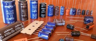
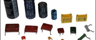
Types of permanent capacitors
There are a large number of models of two-terminal constant-capacity circuits. Let's look at the most popular of them:
- KM - ceramic Soviet capacitors with a high content of precious metals, used in industrial and military equipment;
- KSO - a two-terminal network with a mica dielectric, thanks to which the device operated at high frequencies;
- KTK - ceramic tubular capacitors, most often used for high-frequency technology;
- MBM is a metal-paper capacitor, an important element of old amplifiers and tube devices.
Soviet KM capacitors are highly valued among buyers of old radio equipment. Some models contain a significant amount of expensive metals - silver, platinum, palladium. The cost of a kilogram of capacitors can reach 80,000 rubles!
Operating principle of capacitors
When a circuit is connected to an electrical source, electrical current begins to flow through the capacitor. At the beginning of the passage of current through the capacitor, its strength is at its maximum and the voltage is at its minimum. As the device accumulates charge, the current drops until it disappears completely, and the voltage increases.
During the process of charge accumulation, electrons accumulate on one plate and positive ions on the other. Charge does not flow between the plates due to the presence of a dielectric. This is how the device accumulates charge. This phenomenon is called the accumulation of electric charges, and the capacitor is called an electric field accumulator.
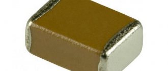
Marking of SMD components
Surface mount SMD components are very small in size, so an abbreviated alphanumeric coding has been developed for them. The letter means the capacitance value in picofarads, the number is a multiplier in the form of a power of ten, for example G4 - 1.8 * 105 picofarads (180 nF). If there are two letters in front, the first one indicates the manufacturer of the component or the operating voltage.
SMD marking
SMD electrolytic capacitors can have the value of the main parameter on the case in the form of a decimal fraction, where instead of a dot the symbol μ can be inserted (the voltage is indicated by the letter V (5V5 - 5.5 volts) or can have a coded value, depending on the manufacturer. The positive terminal is indicated by a stripe on the case .
The marking of capacitors has a large number of options. This is especially true for imported capacitors. You can often find small-sized elements that do not have any designations at all. The parameters can only be determined by direct measurement or by looking at the designation of the capacitors on the electrical diagram. Radioelements produced by different companies may have similar designations, but different parameters. Here, the decoding of the designations should be based on which manufacturer produces the predominant number of similar elements in a particular device.
Characteristics and properties
Capacitor parameters that are used to create and repair electronic devices include:
- Capacity - C. Determines the amount of charge that the device holds. The value of the nominal capacity is indicated on the case. To create the required values, the elements are included in the circuit in parallel or in series. Operational values do not coincide with calculated values.
- Resonant frequency - fр. If the current frequency is greater than the resonant one, then the inductive properties of the element appear. This makes work difficult. To ensure the design power in the circuit, it is reasonable to use a capacitor at frequencies below resonant values.
- Rated voltage - Un. To prevent breakdown of the element, the operating voltage is set less than the rated voltage. The parameter is indicated on the capacitor body.
- Polarity. If the connection is incorrect, breakdown and failure will occur.
- Electrical insulation resistance - Rd. Determines the leakage current of the device. In devices, parts are located close to each other. At high leakage current, parasitic connections in the circuits are possible. This leads to malfunctions. Leakage current worsens the capacitive properties of the element.
- Temperature coefficient - TKE. The value determines how the capacitance of the device changes with fluctuations in ambient temperature. The parameter is used when developing devices for operation in harsh climatic conditions.
- Parasitic piezoelectric effect. Some types of capacitors create noise in devices when deformed.
Breakdowns of tantalum capacitors
When using these effective, but somewhat capricious devices, it is necessary to monitor the occurrence of a failure condition, since they have been known to catch fire when they fail. Failures are due to the fact that, if used incorrectly, tantalum pentoxide changes its amorphous structure to a crystalline one, that is, it turns from a dielectric into a conductor. A change in structures can occur due to too high inrush current. Dielectric breakdown causes an increase in leakage currents, which in turn lead to breakdown of the capacitor itself.
The cause of troubles associated with the operation of tantalum capacitors may be manganese dioxide. The oxygen present in this compound causes the appearance of local fires. Breakdowns with fire are typical for older models. New technologies make it possible to obtain more reliable products.
Breakdowns that occur at high temperatures and voltages can cause an avalanche effect. In this case, the damage often extends over most or all of the device. If the area of crystallized tantalum pentoxide is small, then a self-healing effect often occurs. It is possible due to the transformations occurring in the electrolyte in the event of dielectric breakdown. As a result of all transformations, the crystallized conductor site is surrounded by manganese oxide, which completely neutralizes its conductivity.
Physical quantities used in marking the capacitance of ceramic capacitors
To determine the value of capacitance in the international system of units (SI), the Farad (F, F) is used. This is too large a value for a standard electrical circuit, so smaller units are used in marking household capacitors.
Table of capacitance units used for household ceramic capacitors
| Unit name | Designation options | Power relative to Farad | |
| Microfarad | Microfarad | µF, µF, uF, mF | 10-6F |
| Nanofarad | Nanofarad | nF, nF | 10-9F |
| Picofarad | Picofarad | pF, pF, mmF, uuF | 10-12F |
The off-label unit millifarad is rarely used - 1 mF (10-3F).
Types of markings
At the moment, manufacturers use several types, which can be located on the body either individually or interchangeably. All values below will be purely theoretical, provided for illustrative purposes.
The simplest type of marking - no codes or table substitutions, the capacity is directly written on the body, which immediately provides the end user with real parameters without unnecessary movements. And this method would be used everywhere, if not for its bulkiness - it will be possible to completely write the container only on fairly large products, otherwise it will be impossible to see the inscription even with a magnifying glass. For example: writing 100 µF±6% means that this capacitor has a capacitance of 100 microfarads with a damping of 6% of the total capacitance, which is equal to a value of 94-106 microfarads. It is also possible to use markings of the form 100 µF +8%/-10%, which means unequal damping equal to 90–108 microfarads. This is the simplest and most understandable method, however, such marking is very cumbersome, so it is used on large and very capacitive capacitors.
Marking of large products
Digital marking of capacitors (as well as numerical and alphabetic markings) is used in cases where the small area of the product does not allow a detailed record of the capacitance to be placed. Therefore, certain values are replaced with ordinary numbers and Latin letters, which are deciphered one by one to obtain complete information.
Everything is very simple - if only numbers are used (and on such products there are usually three of them), then you need to decipher them as follows:
- the first two digits indicate the first two digits of the capacity;
- the third digit indicates the number of zeros that must be added after the first two digits;
- such capacitors are always measured in picofarads.
Let's take for example the first option from the picture above with the entry 104. We leave the first two digits as 10. To them we add the number of zeros indicated by the third digit, that is, 4. We get a value of 100,000 picofarads. We return to the table at the beginning of the article, reduce the number of zeros and get an acceptable value of 100 microfarads.
If one or two digits are used, they remain that way. For example, the notations 5 and 15 represent 5 and 15 picofarads, respectively. The .55 marking is equal to 0.55 microfarads.
An interesting notation is made using letters either instead of a dot or as another quantity. For example, 8n2 means 8.2 nanofarads, while n82 means 0.82 nanofarads. For a certain class of capacitors, an additional code marking may be added at the end, for example, 100V.
Labeling of ceramic capacitors using a numerical and alphabetic method is the standard for these products. Here, exactly the same encryption algorithms are used, and the inscriptions themselves are physically applied by the manufacturer to the ceramic surface.
Ceramic capacitors with markings
- An outdated, but still used option is color indication. It was used in Soviet production to simplify the reading of markings even on very small products. The downside is that it is quite problematic to remember such a table right away, so it is advisable to have it on hand, at least at first. The colors are applied to the capacitors, where the marking is done in the form of monotonous stripes. Read as follows: the first two colors indicate the capacitance in picofarads;
- the third color shows the number of zeros that need to be added;
- the fourth and fifth colors respectively show the possible tolerance and nominal voltage supplied to the product.
| Color | Meaning |
| Black | |
| Brown | 1 |
| Red | 2 |
| Orange | 3 |
| Yellow | 4 |
| Green | 5 |
| Blue | 6 |
| Violet | 7 |
| Grey | 8 |
| White | 9 |
Marking of imported capacitors is carried out in similar ways, only the Latin alphabet can be used instead of Cyrillic. For example, on domestic versions there may be 5mk1, which means 5.1 microfarads. Whereas on imported ones this value will look like 5µ If the entry is completely incomprehensible, then you can contact the official manufacturer for clarification; most likely, the website has tables or a program that decipher its markings. However, this occurs only in exceptional cases and is rarely encountered.
Methods for marking capacitor capacity
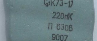
On Soviet-made parts, most often having a fairly large surface area, the numerical values of the capacitance, its unit of measurement and the nominal voltage in volts were applied. For example, 23 pF, that is, 23 picofarads.
Deciphering the markings of modern ceramic capacitors of domestic and foreign production is a more complex undertaking.
What parameters can be indicated in the labeling
Three parameters are important for capacitors:
- capacity;
- rated (operating) voltage;
- Capacity deviation tolerance.
Everything is clear with the first two. It’s just worth noting that on some capacitors the rated voltage may not be indicated. If high voltage is expected, you need to look at the manufacturer's data.
Capacity
The first and most important parameter of a capacitor is capacitance. In this regard, the value of this characteristic is placed in first place and is encoded with an alphanumeric designation. Since the unit of measurement of capacitance is the farad, the letter designation contains either the symbol of the Cyrillic alphabet “F” or the symbol of the Latin alphabet “F”.
Since the farad is a large value, and the elements used in industry have much smaller values, the units of measurement have various diminutive prefixes (mili-, micro-, nano- and pico). Letters of the Greek alphabet are also used to designate them.
- 1 millifarad is equal to 10-3 farads and is denoted 1mF or 1mF.
- 1 microfarad is equal to 10-6 farads and is designated 1 µF or 1F.
- 1 nanofarad is equal to 10-9 farads and is denoted 1nF or 1nF.
- 1 picofarad is equal to 10-12 farads and is denoted 1pF or 1pF.
If the capacity value is expressed as a fraction, then the letter indicating the dimension of the units of measurement is placed in place of the comma. Thus, the designation 4n7 should be read as 4.7 nanofarads or 4700 picofarads, and the inscription like n47 corresponds to a capacity of 0.47 nanofarads or 470 picofarads.
In the case where the capacitor does not have a rating indicated, the integer value indicates that the capacitance is indicated in picofarads, for example, 1000, and the value expressed as a decimal fraction indicates the rating in microfarads, for example, 0.01.
The capacitance of the capacitor indicated on the case rarely corresponds to the actual parameter and deviates from the nominal value within a certain range. The exact capacitance value sought when making capacitors depends on the materials used to manufacture them. The spread of parameters can range from thousandths to tens of percent.
The value of the permissible deviation of the capacitance is indicated on the capacitor body after the nominal value by placing a letter of the Latin or Russian alphabet. For example, the Latin letter J (Russian letter I in the old designation) indicates a deviation range of 5% in one direction or another, and the letter M (Russian V) - 20%.
Such a parameter as the temperature coefficient of capacitance is included in the marking quite rarely and is applied mainly to small-sized elements used in electrical circuits of timing circuits. For identification, either an alphanumeric or color notation system is used.
There is also a combination of letter and color markings. Its options are so diverse that to accurately determine the value of this parameter for each specific type of capacitor, you need to refer to GOSTs or reference books on the corresponding radio components.
Rated voltage
The voltage at which the capacitor will operate for a specified service life while maintaining its characteristics is called the rated voltage. For capacitors of sufficient size, this parameter is applied directly to the body of the element, where the numbers indicate the rated voltage value, and the letters indicate in which units of measurement it is expressed.
For example, the designation 160V or 160V indicates that the nominal voltage is 160 volts. Higher voltages are indicated in kilovolts - kV. On small-sized capacitors, the rated voltage is encoded with one of the letters of the Latin alphabet. For example, the letter I represents a nominal voltage of 1 volt, and the letter Q represents 160 volts.
Date of issue
According to GOST 30668-2000 Electronic products. Marking”, letters and numbers indicating the year and month of production are indicated.
The date when a particular production was carried out can be displayed not only in the form of numbers, but also in the form of letters. Each year has a relationship with a letter from the Latin alphabet. The months from January to September are designated by numbers from one to nine. The month of October has a relationship with the number zero. November corresponds to the Latin letter N, and December – D.
YearCode
| 1990 | A |
| 1991 | B |
| 1992 | C |
| 1993 | D |
| 1994 | E |
| 1995 | F |
| 1996 | H |
| 1997 | I |
| 1998 | K |
| 1999 | L |
| 2000 | M |
| 2001 | N |
| 2002 | P |
| 2003 | R |
| 2004 | S |
| 2005 | T |
| 2006 | U |
| 2007 | V |
| 2008 | W |
| 2009 | X |
| 2010 | A |
| 2011 | B |
| 2012 | C |
| 2013 | D |
| 2014 | E |
| 2015 | F |
| 2016 | H |
| 2017 | I |
| 2018 | K |
| 2019 | L |
Location of markings on the body
Labeling plays an important role on any product. It is often placed on the first line on the case and has a capacity value. The same line involves placing the so-called tolerance value on it. If both applications do not fit on this line, then this can be done on the next one.
A similar system is used to apply film-type condensates. The arrangement of elements must be located according to certain regulations, which are produced by GOST or TU for an element of an individual type.
Capacitor marking table
The capacitance of capacitors can be measured in microfarads (uF), nanofarads (nF), picofarads (pF) and is designated by a special code.
This table will help you understand the markings for various measuring ratings and select the necessary analogs for replacement. There is a universal measuring device for radio components. Can measure inductance, ESR and losses of electrolytic capacitors. It also checks transistors (including MOSFETs), diodes, zener diodes, and quartz. The type of parts is determined automatically and displays the values. In this ESR tester review, I described this device. uF (uF) nF (nF) pF (pF) Code
| 1uF | 1000nF | 1000000pF | 105 |
| 0.82uF | 820nF | 820000pF | 824 |
| 0.8uF | 800nF | 800000pF | 804 |
| 0.7uF | 700nF | 700000pF | 704 |
| 0.68uF | 680nF | 680000pF | 624 |
| 0.6uF | 600nF | 600000pF | 604 |
| 0.56uF | 560nF | 560000pF | 564 |
| 0.5uF | 500nF | 500000pF | 504 |
| 0.47uF | 470nF | 470000pF | 474 |
| 0.4uF | 400nF | 400000pF | 404 |
| 0.39uF | 390nF | 390000pF | 394 |
| 0.33uF | 330nF | 330000pF | 334 |
| 0.3uF | 300nF | 300000pF | 304 |
| 0.27uF | 270nF | 270000pF | 274 |
| 0.25uF | 250nF | 250000pF | 254 |
| 0.22uF | 220nF | 220000pF | 224 |
| 0.2uF | 200nF | 200000pF | 204 |
| 0.18uF | 180nF | 180000pF | 184 |
| 0.15uF | 150nF | 150000pF | 154 |
| 0.12uF | 120nF | 120000pF | 124 |
| 0.1uF | 100nF | 100000pF | 104 |
| 0.082uF | 82nF | 82000pF | 823 |
| 0.08uF | 80nF | 80000pF | 803 |
| 0.07uF | 70nF | 70000pF | 703 |
| 0.068uF | 68nF | 68000pF | 683 |
| 0.06uF | 60nF | 60000pF | 603 |
| 0.056uF | 56nF | 56000pF | 563 |
| 0.05uF | 50nF | 50000pF | 503 |
| 0.047uF | 47nF | 47000pF | 473 |
| 0.04uF | 40nF | 40000pF | 403 |
| 0.039uF | 39nF | 39000pF | 393 |
| 0.033uF | 33nF | 33000pF | 333 |
| 0.03uF | 30nF | 30000pF | 303 |
| 0.027uF | 27nF | 27000pF | 273 |
| 0.025uF | 25nF | 25000pF | 253 |
| 0.022uF | 22nF | 22000pF | 223 |
| 0.02uF | 20nF | 20000pF | 203 |
| 0.018uF | 18nF | 18000pF | 183 |
| 0.015uF | 15nF | 15000pF | 153 |
| 0.012uF | 12nF | 12000pF | 123 |
| 0.01uF | 10nF | 10000pF | 103 |
| 0.0082uF | 8.2nF | 8200pF | 822 |
| 0.008uF | 8nF | 8000pF | 802 |
| 0.007uF | 7nF | 7000pF | 702 |
| 0.0068uF | 6.8nF | 6800pF | 682 |
| 0.006uF | 6nF | 6000pF | 602 |
| 0.0056uF | 5.6nF | 5600pF | 562 |
| 0.005uF | 5nF | 5000pF | 502 |
| 0.0047uF | 4.7nF | 4700pF | 472 |
| 0.004uF | 4nF | 4000pF | 402 |
| 0.0039uF | 3.9nF | 3900pF | 392 |
| 0.0033uF | 3.3nF | 3300pF | 332 |
| 0.003uF | 3nF | 3000pF | 302 |
| 0.0027uF | 2.7nF | 2700pF | 272 |
| 0.0025uF | 2.5nF | 2500pF | 252 |
| 0.0022uF | 2.2nF | 2200pF | 222 |
| 0.002uF | 2nF | 2000pF | 202 |
| 0.0018uF | 1.8nF | 1800pF | 182 |
| 0.0015uF | 1.5nF | 1500pF | 152 |
| 0.0012uF | 1.2nF | 1200pF | 122 |
| 0.001uF | 1nF | 1000pF | 102 |
| 0.00082uF | 0.82nF | 820pF | 821 |
| 0.0008uF | 0.8nF | 800pF | 801 |
| 0.0007uF | 0.7nF | 700pF | 701 |
| 0.00068uF | 0.68nF | 680pF | 681 |
| 0.0006uF | 0.6nF | 600pF | 621 |
| 0.00056uF | 0.56nF | 560pF | 561 |
| 0.0005uF | 0.5nF | 500pF | 52 |
| 0.00047uF | 0.47nF | 470pF | 471 |
| 0.0004uF | 0.4nF | 400pF | 401 |
| 0.00039uF | 0.39nF | 390pF | 391 |
| 0.00033uF | 0.33nF | 330pF | 331 |
| 0.0003uF | 0.3nF | 300pF | 301 |
| 0.00027uF | 0.27nF | 270pF | 271 |
| 0.00025uF | 0.25nF | 250pF | 251 |
| 0.00022uF | 0.22nF | 220pF | 221 |
| 0.0002uF | 0.2nF | 200pF | 201 |
| 0.00018uF | 0.18nF | 180pF | 181 |
| 0.00015uF | 0.15nF | 150pF | 151 |
| 0.00012uF | 0.12nF | 120pF | 121 |
| 0.0001uF | 0.1nF | 100pF | 101 |
| 0.000082uF | 0.082nF | 82pF | 820 |
| 0.00008uF | 0.08nF | 80pF | 800 |
| 0.00007uF | 0.07nF | 70pF | 700 |
| 0.000068uF | 0.068nF | 68pF | 680 |
| 0.00006uF | 0.06nF | 60pF | 600 |
| 0.000056uF | 0.056nF | 56pF | 560 |
| 0.00005uF | 0.05nF | 50pF | 500 |
| 0.000047uF | 0.047nF | 47pF | 470 |
| 0.00004uF | 0.04nF | 40pF | 400 |
| 0.000039uF | 0.039nF | 39pF | 390 |
| 0.000033uF | 0.033nF | 33pF | 330 |
| 0.00003uF | 0.03nF | 30pF | 300 |
| 0.000027uF | 0.027nF | 27pF | 270 |
| 0.000025uF | 0.025nF | 25pF | 250 |
| 0.000022uF | 0.022nF | 22pF | 220 |
| 0.00002uF | 0.02nF | 20pF | 200 |
| 0.000018uF | 0.018nF | 18pF | 180 |
| 0.000015uF | 0.015nF | 15pF | 150 |
| 0.000012uF | 0.012nF | 12pF | 120 |
| 0.00001uF | 0.01nF | 10pF | 100 |
| 0.000008uF | 0.008nF | 8pF | 080 |
| 0.000007uF | 0.007nF | 7pF | 070 |
| 0.000006uF | 0.006nF | 6pF | 060 |
| 0.000005uF | 0.005nF | 5pF | 050 |
| 0.000004uF | 0.004nF | 4pF | 040 |
| 0.000003uF | 0.003nF | 3pF | 030 |
| 0.000002uF | 0.002nF | 2pF | 020 |
| 0.000001uF | 0.001nF | 1pF | 010 |
Marking capacitors with three numbers
With this marking, the first two digits determine the mantissa of the capacity, and the last one determines the exponent in base 10, in other words, to what power do we need to raise the number 10, or even simpler, how many zeros should we add after the first 2 numbers.
The number thus obtained corresponds to the capacitance in picofarads.
If the first digit is “0”, then the capacitance is less than 1pF (010 = 1.0pF). If the last digit is “9” then this means that the exponent is “-1” that we must multiply the mantissa by 10 to the power of “-1” or in other words divide it by 10. picofarad code nanofarads, nF, nF microfarads, μF, μF
| 109 | 1.0 pF | ||
| 159 | 1.5 pF | ||
| 229 | 2.2 pF | ||
| 339 | 3.3 pF | ||
| 479 | 4.7 pF | ||
| 689 | 6.8 pF | ||
| 100 | 10 pF | 0.01 nF | |
| 150 | 15 pF | 0.015 nF | |
| 220 | 22 pF | 0.022 nF | |
| 330 | 33 pF | 0.033 nF | |
| 470 | 47 pF | 0.047 nF | |
| 680 | 68 pF | 0.068 nF | |
| 101 | 100 pF | 0.1 nF | |
| 151 | 150 pF | 0.15 nF | |
| 221 | 220 pF | 0.22 nF | |
| 331 | 330 pF | 0.33 nF | |
| 471 | 470 pF | 0.47 nF | |
| 681 | 680 pF | 0.68 nF | |
| 102 | 1000 pF | 1 nF | |
| 152 | 1500 pF | 1.5 nF | |
| 222 | 2200 pF | 2.2 nF | |
| 332 | 3300 pF | 3.3 nF | |
| 472 | 4700 pF | 4.7 nF | |
| 682 | 6800 pF | 6.8 nF | |
| 103 | 10000 pF | 10 nF | 0.01 µF |
| 153 | 15000 pF | 15 nF | 0.015 µF |
| 223 | 22000 pF | 22 nF | 0.022 µF |
| 333 | 33000 pF | 33 nF | 0.033 µF |
| 473 | 47000 pF | 47 nF | 0.047 µF |
| 683 | 68000 pF | 68 nF | 0.068 µF |
| 104 | 100000 pF | 100 nF | 0.1 µF |
| 154 | 150000 pF | 150 nF | 0.15 µF |
| 224 | 220000 pF | 220 nF | 0.22 µF |
| 334 | 330000 pF | 330 nF | 0.33 µF |
| 474 | 470000 pF | 470 nF | 0.47 µF |
| 684 | 680000 pF | 680 nF | 0.68 µF |
| 105 | 1000000 pF | 1000 nF | 1 µF |
Marking capacitors with four numbers
Everything is the same as above, only the first three digits determine the mantissa, and the last one is the exponent in base 10, to obtain the capacitance in picofarads.
Example notation:
1622 = 162*102 pF = 16200 pF = 16.2 nF
Alphanumeric marking
With this marking, the letter indicates the decimal point and designation (uF, nF, pF), and the numbers indicate the capacitance value:
15p = 15 pF, 22p = 22 pF, 2n2 = 2.2 nF, 4n7 = 4.7 nF, μ33 = 0.33 µF
The letter R is also used for designation; it is used to designate capacitances in microfarads. And if there is a zero in front of “R”, then this means that the capacitance is in picofarads.
An example of alphanumeric marking of a designation:
0R5 = 0.5 pF, R47 = 0.47 µF, 6R8 = 6.8 µF
Marking capacitors using a numerical-alphabetic code.
The marking of capacitors may indicate the following parameters: Type of capacitor, its rated capacity, permissible deviation of capacitance, Temperature Coefficient of Capacitance (TKE), rated operating voltage.
The order of marking may be different - the first line may be the rated voltage, TKE or the manufacturer's brand name. TKE may be absent altogether, the rated voltage is also not always indicated! There is almost always a marking of the nominal capacity. As for capacity, there are various ways to encode it symbolically. 1. Marking of the container using three numbers. With this marking, the first two digits indicate the capacitance value in picofarads, and the last one indicates the bit depth, i.e., the number of zeros that must be added to the first two digits. But if the last digit is “9”, division by 10 occurs.
| Code | Capacitance(pF) | Capacitance(nF) | Capacitance(uF) |
| 109 | 1.0(pF) | 0.001(nF) | 0.000001(uF) |
| 159 | 1.5(pF) | 0.0015(nF) | 0.0000015(uF) |
| 229 | 2.2(pF) | 0.0022(nF) | 0.0000022(uF) |
| 339 | 3.3(pF) | 0.0033(nF) | 0.0000033(uF) |
| 479 | 4.7(pF) | 0.0047(nF) | 0.0000047(uF) |
| 689 | 6.8(pF) | 0.0068(nF) | 0.0000068(uF) |
| 100 | 10(pF) | 0.01(nF) | 0.00001(uF) |
| 150 | 15(pF) | 0.015(nF) | 0.000015(uF) |
| 220 | 22(pF) | 0.022(nF) | 0.000022(uF) |
| 330 | 33(pF) | 0.033(nF) | 0.000033(uF) |
| 470 | 47(pF) | 0.047(nF) | 0.000047(uF) |
| 680 | 68(pF) | 0.068(nF) | 0.000068(uF) |
| 101 | 100(pF) | 0.1(nF) | 0.0001(uF) |
| 151 | 150(pF) | 0.15(nF) | 0.00015(uF) |
| 221 | 220(pF) | 0.22(nF) | 0.00022(uF) |
| 331 | 330(pF) | 0.33(nF) | 0.00033(uF) |
| 471 | 470(pF) | 0.47(nF) | 0.00047(uF) |
| 681 | 680(pF) | 0.68(nF) | 0.00068(uF) |
| 102 | 1000(pF) | 1(nF) | 0.001(uF) |
| 152 | 1500(pF) | 1.5(nF) | 0.0015(uF) |
| 222 | 2200(pF) | 2.2(nF) | 0.0022(uF) |
| 332 | 3300(pF) | 3.3(nF) | 0.0033(uF) |
| 472 | 4700(pF) | 4.7(nF) | 0.0047(uF) |
| 682 | 6800(pF) | 6.8(nF) | 0.0068(uF) |
| 103 | 10000(pF) | 10(nF) | 0.01(uF) |
| 153 | 15000(pF) | 15(nF) | 0.015(uF) |
| 223 | 22000(pF) | 22(nF) | 0.022(uF) |
| 333 | 33000(pF) | 33(nF) | 0.033(uF) |
| 473 | 47000(pF) | 47(nF) | 0.047(uF) |
| 683 | 68000(pF) | 68(nF) | 0.068(uF) |
| 104 | 100000(pF) | 100(nF) | 0.1(uF) |
| 154 | 150000(pF) | 150(nF) | 0.15(uF) |
| 224 | 220000(pF) | 220(nF) | 0.22(uF) |
| 334 | 330000(pF) | 330(nF) | 0.33(uF) |
| 474 | 470000(pF) | 470(nF) | 0.47(uF) |
| 684 | 680000(pF) | 680(nF) | 0.68(uF) |
| 105 | 1000000(pF) | 1000(nF) | 1.0(uF) |
2. The second option - marking is done not in pico, but in microfarads, and the letter µ is placed instead of the decimal point.
| Code | Capacitance(uF) |
| µ1 | 0,1 |
| µ47 | 0,47 |
| 1 | 1,0 |
| 4µ7 | 4,7 |
| 10µ | 10,0 |
| 100µ | 100,0 |
3. Third option.
| Code | Capacitance(uF) |
| p10 | 0.1pF |
| IP5 | 0.47pF |
| 332p | 332pF |
| 1HO or 1no | 1nF |
| 15H or 15no | 15.0nF |
| 33H2 or 33n2 | 33.2nF |
| 590H or 590n | 590nF |
| m15 | 0.15uF |
| 1m5 | 1.5uF |
| 33m2 | 33.2uF |
| 330m | 330uF |
| 10m | 10.0uF |
Soviet capacitors used “p” instead of the Latin “r”.
The permissible deviation of the nominal capacity is marked with a letter, often the letter follows the code defining the capacity (the same line).
| Letter designation | Tolerance(%) |
| B | ± 0,1 |
| C | ± 0,25 |
| D | ± 0,5 |
| F | ± 1 |
| G | ± 2 |
| J | ± 5 |
| K | ± 10 |
| M | ± 20 |
| N | ± 30 |
| Q | -10…+30 |
| T | -10…+50 |
| Y | -10…+100 |
| S | -20…+50 |
| Z | -20…+80 |
Further, there may be (or may not be!) marking of the Temperature Coefficient of Capacity (TKE). For capacitors with non-standardized TKE, coding is done using letters.
| Tolerance at -60²…+85²(%) designation | Letter code |
| ± 10 | B |
| ± 20 | Z |
| ± 30 | D |
| ± 50 | X |
| ± 70 | E |
| ± 90 | F |
Capacitors with a linear dependence on temperature.
| TKE(ppm/²C) | Letter code |
| 100(+130….-49) | A |
| 33 | N |
| 0(+30….-47) | C |
| -33(+30….-80) | H |
| -75(+30….-80) | L |
| -150(+30….-105) | P |
| -220(+30….-120) | R |
| -330(+60….-180) | S |
| -470(+60….-210) | T |
| -750(+120….-330) | U |
| -500(-250….-670) | V |
| -2200 | K |
Next comes the voltage in volts, most often in the form of a regular number. For example, the capacitor in this picture is marked with two lines. The first (104J) means that its capacitance is 0.1 μF (104), the permissible deviation of the capacitance does not exceed ± 5% (J). The second (100V) is the voltage in volts.
In addition, the voltage of the capacitors can also be encoded using letters (see table below).
| Voltage (V) | Letter code |
| 1 | I |
| 1,6 | R |
| 3,2 | A |
| 4 | C |
| 6,3 | B |
| 10 | D |
| 16 | E |
| 20 | F |
| 25 | G |
| 32 | H |
| 40 | C |
| 50 | J |
| 63 | K |
| 80 | L |
| 100 | N |
| 125 | P |
| 160 | Q |
| 200 | Z |
| 250 | W |
| 315 | X |
| 400 | Y |
| 450 | U |
| 500 | V |
Marking SMD capacitors.
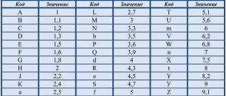
The dimensions of SMD capacitors are small, so their marking is done very succinctly. The operating voltage is often coded by letter (2nd and 3rd options in the figure below) in accordance with the data provided in the previous section. The nominal capacity can be encoded either using a three-digit digital code (option 2 in the figure) or using a two-digit alphanumeric code (option 1 in the figure). When using the latter, you can still find two (and not one letter) with one number on the case (option 3 in the figure).
The first letter can be either a manufacturer's code (which is not always interesting) or indicate the rated operating voltage (more useful information), the second can be an encoded value in picoFarads (mantissa). The number is an exponent (indicates how many zeros need to be added to the mantissa). For example, EA3 may mean that the rated voltage of the capacitor is 16V(E) and the capacitance is 1.0 * 1000 = 1 nanofarad, BF5, respectively, the voltage is 6.3V(V), the capacitance is 1.6 * 100000 = 0.1 microfarad and. etc.
| Letter | Mantissa. |
| A | 1,0 |
| B | 1,1 |
| C | 1,2 |
| D | 1,3 |
| E | 1,5 |
| F | 1,6 |
| G | 1,8 |
| H | 2,0 |
| J | 2,2 |
| K | 2,4 |
| L | 2,7 |
| M | 3,0 |
| N | 3,3 |
| P | 3,6 |
| Q | 3,9 |
| R | 4,3 |
| S | 4,7 |
| T | 5,1 |
| U | 5,6 |
| V | 6,2 |
| W | 6,8 |
| X | 7,5 |
| Y | 8,2 |
| Z | 9,1 |
| a | 2,5 |
| b | 3,5 |
| d | 4,0 |
| e | 4,5 |
| f | 5,0 |
| m | 6,0 |
| n | 7,0 |
| t | 8,0 |
How to decipher the markings of a capacitor and find out its capacity?
Basic information about the characteristics of capacitors, which are components of almost all electronic circuits, is usually placed on their cases. Depending on the standard size of the element, manufacturer, production time, the data applied to the electronic device constantly changes not only in composition, but also in appearance.
With a decrease in the size of the case, the composition of alphanumeric designations was changed, encoded, and replaced by color markings. The variety of internal standards used by manufacturers of radio-electronic elements requires certain knowledge to correctly interpret the information printed on an electronic device.
Color coding of ceramic capacitors.
Colored stripes are applied on the capacitor body, from left to right, or from top to bottom. As a rule, the capacity value is encoded by the first three stripes. Each color in the first two stripes has its own number: black - number 0; brown - 1; red - 2; orange - 3; yellow - 4; green - 5; blue - 6; purple - 7; gray - 8; white - 9. Thus, if, for example, the first stripe is brown and the second is yellow, then this corresponds to the number -14. But this number will not be the value of the nominal capacitance of the capacitor; it still needs to be multiplied by the multiplier encoded by the third stripe.
In the third stripe, the colors have the following meanings: orange - 1000; yellow - 10000; green - 100000. Let's assume that the color of the third strip of our capacitor is yellow. We multiply 14 by 10000, we get the capacity in picofarads -140000, otherwise, 140 nanofarads or 0.14 microfarads. The fourth strip indicates permissible deviations from the nominal capacity (accuracy), as a percentage: white - ± 10%; black - ± 20%. The fifth bar is the rated operating voltage. Red color - 250 Volts, yellow - 400.
How are large capacitors marked?
To correctly read the technical specifications of a device, some preparation is necessary. You need to start studying with units of measurement. To determine capacitance, a special unit is used - farad (F). The value of one farad for a standard circuit seems too large, so household capacitors are marked in smaller units. The most commonly used is mF = 1 µF (microfarad), which is 10-6 farads.
In calculations, an off-label unit can be used - millifarad (1mF), which has a value of 10-3 farads. In addition, designations can be in nanofarads (nF) equal to 10-9 F and picofarads (pF) equal to 10-12 F.
Capacitance markings for large capacitors are applied directly to the housing. In some designs, the markings may differ, but in general, you need to be guided by the units of measurement mentioned above.
Designations are sometimes written in capital letters, for example, MF, which actually corresponds to mF - microfarads. The marking fd is also found - an abbreviated English word farad. Therefore mmfd will correspond to mmf or picofarad. In addition, there are designations that include a number and one letter. This marking looks like 400m and is used for small capacitors.
In some cases, it is possible to apply tolerances, which are an acceptable deviation from the rated capacitance of the capacitor. This information is of great importance when, when assembling certain types of electrical circuits, capacitors with precise capacitance values may be required. If we take the marking 6000uF + 50%/-70% as an example, then the maximum capacitance value will be 6000 + (6000 x 0.5) = 9000 uF, and the minimum 1800 uF = 6000 - (6000 x 0.7).
If there are no percentages, you need to find the letter. Usually it is located separately or after the numeric designation of the container. Each letter corresponds to a specific tolerance value. After this, you can begin to determine the rated voltage.
With large capacitor housing sizes, voltage markings are indicated by numbers followed by letters or letter combinations in the form V, VDC, WV or VDCW. The WV symbols correspond to the English phrase WorkingVoltage, which means operating voltage. Digital readings are considered to be the maximum permissible capacitor voltage, measured in volts.
If there is no voltage marking on the device body, such a capacitor should only be used in low-voltage circuits. In an AC circuit, use a device designed specifically for this purpose. Capacitors designed for direct current cannot be used without the ability to convert the rated voltage.
The next step is to identify the positive and negative symbols that indicate the presence of polarity. Determining the positive and negative is of great importance, since incorrect determination of the poles can lead to a short circuit and even explosion of the capacitor. In the absence of special markings, the device can be connected to any terminals, regardless of polarity.
The pole designation is sometimes applied in the form of a colored stripe or a ring-shaped indentation. This marking corresponds to the negative contact in electrolytic aluminum capacitors, which are shaped like a tin can. In tantalum capacitors with very small dimensions, these same symbols indicate positive contact
If there are plus and minus symbols, the color coding can be ignored
Color coding of electrolytic capacitors.
As for small-sized electrolytic capacitors, their nominal capacity is coded using two stripes and one color spot. The first and second bars determine the number, and the spot determines the multiplier. The color coding of the first two stripes of electrolytic capacitors fully corresponds to the marking of ceramic capacitors. It is only necessary to take into account that the capacitance value of “electrolytes” is obtained in microfarads, and not picofarads as with ceramic capacitors. The color of the spot indicating the multiplier: black - 1; brown - 10; red - 100; gray - 0.01; white - 0.1; For example, the color of the first stripe is blue (number 6), the second is orange (number 3), and the color of the spot is brown (multiplier - 10). This means 63*10= 630 microfarads. If an electrolytic capacitor has a third stripe, then it determines its rated voltage: white color - 3 volts; yellow - 6.3 volts; black - 10 volts; green - 16 volts; blue - 20 volts; gray - 25 volts; pink - 35 volts.
The positive terminal in such electrolytic capacitors is thicker than the negative terminal.
Color marking of domestic radioelements
In the production of lines with so-called automatic types of installation, color application appeared, as well as its direct significance in the entire system.
Today, the most commonly used application is using four colors. In this case, we resorted to using four stripes. So, the first strip together with the second represents the capacitance value in so-called picofarads. The third band indicates the deviation that can be allowed. And the fourth band, in turn, means the voltage of the nominal type.
We give you an example of how this or that element is designated - capacity - 23 * 106 picofarads (24 F), permissible deviation from the nominal value - ± 5%, rated voltage - 57 V.
Fixed capacitors
Fixed capacitors are used in various circuits to separate the alternating and direct current components and smooth out the ripple of rectifier voltages. In combination with other circuit elements, capacitors form resonant circuits widely used in radio equipment. Fixed capacitors are classified according to their rated capacitance, accuracy class, rated operating voltage, purpose, dielectric material and design features.
The nominal values of capacitances of capacitors are established by GOST 2519 - 60. During the manufacture of capacitors, the actual value of the capacitance differs from the nominal value indicated in the marking. The permissible deviation of the capacitance from the nominal value is called tolerance. According to this principle, all capacitors are divided into five classes: 0, 1, II, III, IV, their tolerances are respectively ±2%; ±5%; ±10%; ±20% and from - 20 to + 50%.
Depending on the purpose, there are loop, separating, blocking and filter capacitors. Based on the dielectric material, capacitors are divided into mica, ceramic, paper, metal-paper, paper-oil, film, glass-enamel, glass-ceramic, electrolytic, air, vacuum, gas-filled. Based on their design, capacitors are divided into tubular, disk, barrel, pot, crimped and sealed, flat and cylindrical, etc.
Regardless of the type, the capacitor is characterized by its operating voltage. The operating voltage is the voltage under which the capacitor plates can remain for a long time without breakdown of the dielectric separating them. Operating voltage is expressed in volts. Of great importance for the normal operation of the capacitor is the resistance of its insulation. With low insulation resistance, leaks occur that disrupt the normal operation of the circuit. Losses in a capacitor are characterized by the dielectric loss tangent, which expresses the ratio of the power of active losses to the reactive power of the capacitor.
In low-power capacitors, energy losses are mainly caused by dielectric conductivity and dielectric hysteresis, i.e., losses due to rotation of polar molecules in the direction of the field when voltage is applied to the plates. Losses in the plates and leads are small, so they are usually neglected. One of the most important characteristics of a capacitor is stability—the constant value of the capacitor’s capacitance during operation. The change in capacity can be either temporary or irreversible. The main factor influencing the stability of the capacitance of the capacitor is the effect of ambient temperature and heating of the capacitor due to the power dissipated on it. As the temperature rises, the geometric dimensions of the material increase, which entails a temporary (until the temperature returns to its original value) change in capacity.
Marking of imported capacitors
To date, the standards that have been adopted from the IEC apply not only to foreign types of equipment, but also to domestic ones. This system involves applying a code type marking to the product body, which consists of three direct numbers.
The two numbers that are located from the very beginning indicate the capacity of the item and in units such as picofarads. The number that is located third in order is the number of zeros. Let's look at this using the example of 555 - that's 5,500,000 picofarads. In the event that the capacity of the product is less than one picofarad, then the number zero is indicated from the very beginning.
There is also a three-digit type of encoding. This type of application is used exclusively for parts that are highly precise.
Color coding of imported capacitors
The designation of names on an object such as a capacitor has the same production principle as on resistors. The first stripes on two rows indicate the capacity of this device in the same measurement units. The third stripe has a designation indicating the number of immediate zeros. But at the same time, the blue color is completely absent; blue is used instead.
It is important to know that if the colors are the same in a row, then it is advisable to create gaps between them so that it is clearly understood. Indeed, in another case, these stripes will merge into one.
Other markings
The markings on the capacitor body allow you to determine the voltage value. The figure shows special symbols that correspond to the maximum permissible voltage for a particular device. In this case, parameters are given for capacitors that can only be operated at constant current.
In some cases, marking capacitors is greatly simplified. For this purpose, only the first digit is used. For example, zero will mean a voltage below 10 volts, a value of 1 - from 10 to 99 volts, 2 - from 100 to 999 V, and so on, according to the same principle.
Other markings apply to capacitors that were manufactured much earlier or intended for special purposes. In such cases, it is recommended to use special reference books to avoid serious mistakes when assembling the electrical circuit.
Source: electric-220.ru
Some notes and tips on working with capacitors
It must be remembered that capacitors with a higher rated voltage should be selected as the ambient temperature increases, creating a larger voltage reserve to ensure high reliability. If the maximum constant operating voltage of the capacitor is specified, this refers to the maximum temperature (unless otherwise stated). Therefore, capacitors always operate with a certain margin of safety. And yet, it is desirable to ensure that their actual operating voltage is at a level of 0.5-0.6 nominal.
If a limit value for alternating voltage is specified for a capacitor, then this applies to a frequency of (50-60) Hz. For higher frequencies or in the case of pulsed signals, the operating voltages should be further reduced to avoid overheating of the devices due to dielectric losses. High-capacity capacitors with low leakage currents are able to retain the accumulated charge for a long time after the equipment is turned off. To ensure faster discharge, for greater safety, you should connect a resistor with a resistance of 1 MOhm (0.5 W) in parallel with the capacitor.
Sources
- https://hmelectro.ru/poleznye_statyi/markirovka-kondensatorov-tsifrovaya-tsvetnaya-eyo-rasshifrovka
- https://odinelectric.ru/equipment/electronic-components/kak-rasshifrovat-markirovku-kondensatora
- https://www.radiodetector.ru/markirovka-kondensatorov/
- https://www.RadioElementy.ru/articles/markirovka-keramicheskikh-kondensatorov/
- https://instanko.ru/elektroinstrument/markirovka-keramicheskih-kondensatorov-rasshifrovka-tablica.html
- https://ElectroInfo.net/kondensatory/kak-oboznachajutsja-kondensatory-na-sheme.html