What is a capacitor?
A device that stores electricity in the form of electrical charges is called a capacitor.
The amount of electricity or electric charge in physics is measured in coulombs (C). Electrical capacitance is calculated in farads (F).
A solitary conductor with an electrical capacity of 1 farad is a metal ball with a radius equal to 13 radii of the Sun. Therefore, a capacitor includes at least 2 conductors, which are separated by a dielectric. In simple device designs, paper is used.
The operation of a capacitor in a DC circuit is carried out when the power is turned on and off. Only during transient moments does the potential on the plates change.
The capacitor in the AC circuit recharges at a frequency equal to the frequency of the power source voltage. As a result of continuous charges and discharges, current flows through the element. A higher frequency means the device recharges faster.
The resistance of the circuit with a capacitor depends on the frequency of the current. At zero frequency of direct current, the resistance value tends to infinity. As the AC frequency increases, the resistance decreases.
Calculation of capacitor parameters online
I don’t know about you, but I never liked working and calculating capacitances of capacitors. What was most annoying was the presence in the source data of capacitances in different denominations, in picofarads, nanofarads, microfarads. They had to be converted to Farads, which entailed the most stupid errors in calculations.
A capacitor is, in principle, any structure that can store stored electrical potential. If this design not only stores electricity, but also generates it, then this is already a power source and not a capacitor.
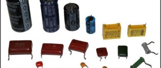
The design of capacitors can be any, but most often in practice a flat capacitor is used, consisting of two conducting plates, between which there is some kind of dielectric.
This is due to the fact that the calculation of the capacitance of such a capacitor is carried out according to a well-known formula and the simplicity of its creation.
By rolling such a flat capacitor into a roll, we get that despite the actual modest size of the “roll”, there is a flat capacitor tens of centimeters long and with increased capacity.
The capacitances of some forms of capacitors are known, and we will consider them further.
But I would like to note that, in our opinion, the development potential of capacitors has not been fully completed.
After all, the design of any capacitor can have any shape, the materials from which the plates are made or the dielectric layer can also be anything within the limits of the periodic table.
The only difficulty is the impossibility of theoretically calculating the potential capacity of a newly created (different design) capacitor. This makes it difficult to find the best capacitor design.
This bot calculates the parameters of typical capacitor shapes. The difference from other calculators present on the Internet is the ability to set parameters that you know in order to calculate the rest.
And the last innovation that you can use. You don't necessarily have to convert given data to meters, farads, etc. It is enough to indicate the dimension of the data.
- For example, if the capacitance is known and equal to 100 picofarads, then the bot can write c = 100 picofarads or c = 100 pF, and the bot itself will convert to Farads.
- The result will also be presented optimally for the user’s visual perception.
- This became possible with the creation of a bot System of units of measurement online
Flat capacitor. Options
| Obtained characteristics of a parallel-plate capacitor |
The simplest and most common capacitor design is two flat conductors separated by a thin layer of dielectric (that is, a material that does not conduct electric current).
The capacity of such a structure is determined by the following formula.
where ε0 = 8.85.10-12 F/m - absolute dielectric constant
If the capacitor consists not of a pair of plates, but of some nth number of flat plates, then the capacitance of such a “layer” capacitor will be
The shape of such a “layered” capacitor looks even more interesting if the layers contain different dielectrics of different thickness d
- S is the area of one of the capacitor plates (we assume that the other plate has the same area)
- d - distance between plates
- C - capacitance of the capacitor
- Let's look at examples
Problem: The capacitance of a flat capacitor is 350 nanofarads, the distance between the plates is 1 millimeter, and is filled with air. Determine the area of the plates?
We tell the bot what we know: C=350nF, d=1mm. Since air has a dielectric constant of 1.00059, then e = 1.00059. We’ll clear the area field, so that’s what we’ll define
We get this answer
| Obtained characteristics of a parallel-plate capacitor |
| d = 1 millimeter e = 1.00059 C = 350 nanofarads S = 39.524703024086 m2 |
Answer, the area of the capacitor plates with such values should be almost 40 square meters.
Operating principle of capacitors
When a circuit is connected to an electrical source, electrical current begins to flow through the capacitor. At the beginning of the passage of current through the capacitor, its strength is at its maximum and the voltage is at its minimum. As the device accumulates charge, the current drops until it disappears completely, and the voltage increases.
During the process of charge accumulation, electrons accumulate on one plate and positive ions on the other. Charge does not flow between the plates due to the presence of a dielectric. This is how the device accumulates charge. This phenomenon is called the accumulation of electric charges, and the capacitor is called an electric field accumulator.
Characteristics and properties
Capacitor parameters that are used to create and repair electronic devices include:
- Capacity - C. Determines the amount of charge that the device holds. The value of the nominal capacity is indicated on the case. To create the required values, the elements are included in the circuit in parallel or in series. Operational values do not coincide with calculated values.
- Resonant frequency - fр. If the current frequency is greater than the resonant one, then the inductive properties of the element appear. This makes work difficult. To ensure the design power in the circuit, it is reasonable to use a capacitor at frequencies below resonant values.
- Rated voltage - Un. To prevent breakdown of the element, the operating voltage is set less than the rated voltage. The parameter is indicated on the capacitor body.
- Polarity. If the connection is incorrect, breakdown and failure will occur.
- Electrical insulation resistance - Rd. Determines the leakage current of the device. In devices, parts are located close to each other. At high leakage current, parasitic connections in the circuits are possible. This leads to malfunctions. Leakage current worsens the capacitive properties of the element.
- Temperature coefficient - TKE. The value determines how the capacitance of the device changes with fluctuations in ambient temperature. The parameter is used when developing devices for operation in harsh climatic conditions.
- Parasitic piezoelectric effect. Some types of capacitors create noise in devices when deformed.
Method 2. Using a frequency converter “Chastotnik”
An asynchronous frequency converter is used to convert mains three-phase or single-phase alternating current with a frequency of 50 (60) Hz into three-phase or single-phase current with a frequency from 1 Hz to 800 Hz.
For our purpose, frequency converters are suitable for converting a single-phase electrical network into a three-phase one. The industry produces two types of similar converters with output for three phases of operating voltage 220V and output for three phases of operating voltage 380V. In the first case, a 220V asynchronous electric motor is connected to a frequency converter in a “delta” circuit, in the second case, a 380V in a “star” circuit.
Using a frequency converter with an asynchronous electric motor has many advantages:
- Economical - using frequency control of the electric motor reduces energy consumption.
- Protection of the electric motor in many ways - short circuit of the winding to the housing (ground), protection of the motor from overvoltage, protection from overcurrent, protection from possible undervoltage, control of the phases of the output circuit, control of the phases of the supply circuit, protection of the electric drive from operation with underload, protection of the motor from jamming, engine overload protection.
- Possibility of controlling the electric motor - adjusting the speed of the electric motor, turning on/off and changing the speed of the electric motor by monitoring the parameters of various sensors.
- 100% efficiency when converting a single-phase network into a three-phase one - a three-phase asynchronous electric motor operates at 100% of its power.
Although using a frequency converter to obtain a three-phase network from a single-phase one has a huge advantage over other methods, there is also a controversial point; connecting an electric motor to the frequency converter according to the included instructions will not be difficult and the motor will work as it should when turned on, but in order to use all Its functionality requires skills in working with CNC (computer numerical control).
You can buy a frequency converter with delivery in our partner store:
| Brand name: | SAKO |
| Type: | AC/DC/AC converters |
| Size: | 160 x 100 x 130 mm. |
| Model number: | SKI780-0D75-1/SKI780-1D5-1/SKI780-2D2-1 |
| Output frequency: | 0 - 500 HZ |
| Weight: | 1.5 kg. |
| Input voltage: | 220 V. single phase |
| Output voltage: | 220 V. three phases |
Order on AliExpress
| Brand name: | COOLCLASSIC |
| Type: | AC/DC/AC converters |
| Size: | 160 x 100 x 130 mm. |
| Model number: | AT1-1.5KW; AT1-2.2KW; AT1-4KW; AT1-5.5KW |
| Output frequency: | 0-400hz |
| Output power: | 1.5 - 5.5 kW. |
| Weight: | 1.65 kg. |
| Input voltage: | 220 V. Single phase. |
| Output voltage: | 220 V. Three phases |
Order on AliExpress
| Brand name: | COOLCLASSIC |
| Type: | AC/DC/AC converters |
| Size: | 101 x 171 x 137 mm. |
| Output frequency: | 0-400hz |
| Output power: | 3 - 7.5 kW. |
| Weight: | 1.65 kg. |
| Input voltage: | 220 V. Single phase |
| Output voltage: | 220 V. Three phases |
Order on AliExpress
| Brand name: | COOLCLASSIC |
| Type: | AC/DC/AC converters |
| Size: | 180 x 150 x 150 mm. |
| Model number: | 1.5KW -7KW 380V Inverter |
| Output frequency: | 0 - 400 HZ |
| Weight: | 2.3 kg. |
| Input voltage: | 380 V. three phase |
| Output voltage: | 380 V. three phase |
Order on AliExpress
Physical quantities used in marking the capacitance of ceramic capacitors
To determine the value of capacitance in the international system of units (SI), the Farad (F, F) is used. This is too large a value for a standard electrical circuit, so smaller units are used in marking household capacitors.
Table of capacitance units used for household ceramic capacitors
| Unit name | Designation options | Power relative to Farad | |
| Microfarad | Microfarad | µF, µF, uF, mF | 10-6F |
| Nanofarad | Nanofarad | nF, nF | 10-9F |
| Picofarad | Picofarad | pF, pF, mmF, uuF | 10-12F |
The off-label unit millifarad is rarely used - 1 mF (10-3F).
Capacitance unit
Capacitor capacity: formula
Capacitance indicators are usually measured in farads. In Russia, in calculations, it is customary to abbreviate the name of the unit to the capital letter F; in international documents it is called the Latin letter F. It is named after the English physicist Michael Faraday. The value of 1 F is taken to be such a capacitance at which, when transporting a one-coulomb charge from one plate to another (or from one point to another), the voltage between them will change by one volt.
Unit of measurement of electrical capacity in other systems
The use of the farad to describe capacitance was introduced into the SI system in 1960. In the Gaussian system, a statfarad is used for this. It is customary to abbreviate such a unit in writing as statf. 1 statF is approximately equal to 1.11 picofarads and describes the capacitance of a sphere having a radius of 1 centimeter and placed in a vacuum environment. You can convert the values of a particular quantity in non-systemic units into those accepted in SI using special calculators.
Marking of domestic capacitors
All post-Soviet enterprises are characterized by fairly complete labeling of radioelements, allowing for minor differences in designations.
Capacity
The first and most important parameter of a capacitor is capacitance. In this regard, the value of this characteristic is placed in first place and is encoded with an alphanumeric designation. Since the unit of measurement of capacitance is the farad, the letter designation contains either the symbol of the Cyrillic alphabet “F” or the symbol of the Latin alphabet “F”.
Since the farad is a large value, and the elements used in industry have much smaller values, the units of measurement have a variety of diminutive prefixes (mili-, micro-, nano- and pico). Letters of the Greek alphabet are also used to designate them.
- 1 millifarad is equal to 10-3 farads and is denoted 1mF or 1mF.
- 1 microfarad is equal to 10-6 farads and is designated 1 µF or 1F.
- 1 nanofarad is equal to 10-9 farads and is denoted 1nF or 1nF.
- 1 picofarad is equal to 10-12 farads and is denoted 1pF or 1pF.
Marking of imported capacitors
To date, the standards that have been adopted from the IEC apply not only to foreign types of equipment, but also to domestic ones. This system involves applying a code type marking to the product body, which consists of three direct numbers.
The two numbers that are located from the very beginning indicate the capacity of the item and in units such as picofarads. The number that is located third in order is the number of zeros. Let's look at this using the example of 555 - that's 5,500,000 picofarads. In the event that the capacity of the product is less than one picofarad, then the number zero is indicated from the very beginning.
There is also a three-digit type of encoding. This type of application is used exclusively for parts that are highly precise.
Color coding of imported capacitors
The designation of names on an object such as a capacitor has the same production principle as on resistors. The first stripes on two rows indicate the capacity of this device in the same measurement units. The third stripe has a designation indicating the number of immediate zeros. But at the same time, the blue color is completely absent; blue is used instead.
It is important to know that if the colors are the same in a row, then it is advisable to create gaps between them so that it is clearly understood. Indeed, in another case, these stripes will merge into one.
Connecting LEDs to the power supply
A computer power supply is an excellent power source for an LED or string of LEDs because it produces a regulated voltage of +5 volts (V) and +12 V.
So, the connector has four contacts, to which four wires are suitable: two of them are black - this is “zero”, one red produces a voltage of +5 volts, and one yellow produces a voltage of +12 volts.
Consider the connection diagram for one LED.
| When powered from 5 V, a limiting resistor with a value of 100 to 200 Ohms must be connected in series with the LED. |
| When powered from 12 V, a limiting resistor with a value of 400 to 900 Ohms must be connected in series with the LED. |
Let's consider a diagram for connecting two LEDs.
| When powering two LEDs from 5 volts, a resistor of up to 100 ohms must be included in the circuit. Some LEDs in such a circuit will glow too dimly (even without a resistor). |
| When powering two LEDs from 12 V, a resistor from 250 to 600 Ohms must be included in the circuit. |
Consider the connection diagram for three and four LEDs.
| When powering three LEDs from 12 V, you should use a resistor rated from 100 to 250 ohms. |
| Some LEDs in this connection circuit will glow too dimly (even without a resistor). |
The universal principle for calculating the limiting resistor is described in the article “Methodology for calculating LED power supply.”
Above are diagrams for sequential connection of LEDs. There are also ways to parallel LEDs
Please note that parallel connection means a circuit in which, when the anodes and cathodes of all LEDs directly converge into two points (two beams)
Such schemes, as a rule, are not economical and unsafe, both for the power supply and for LEDs. In addition, parallel circuits are more complex in calculations and demanding on the power source, so we will use them only in special cases. Let's just see what this scheme looks like.
| When connecting LEDs in parallel, only identical LEDs should be used, with minimal variation in characteristics. The resistance of the limiting resistor must be calculated and selected with a high degree of accuracy. If one of the LEDs fails, the rest can burn out one after another in a matter of minutes. |
I recommend never using this LED circuit. But if, nevertheless, conditions require parallel connection, then I advise you to use the following option.
| This circuit of parallel connection of LEDs is practically free of the danger of sequential burnout of LEDs. In this case, instead of a limiting resistor, several conventional rectifier diodes of different brands (NOT LEDs) are included. |
Thanks to the voltage drop across these diodes, the voltage reaching the LEDs is no longer 5 Volts, but much less. Limiting diodes are selected so that a voltage equal to their voltage drop in the open state reaches the LEDs.
This circuit is used by the author for round-the-clock LED lighting of the apartment.
Methods for marking capacitor capacity
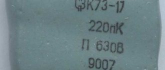
On Soviet-made parts, most often having a fairly large surface area, the numerical values of the capacitance, its unit of measurement and the nominal voltage in volts were applied. For example, 23 pF, that is, 23 picofarads.
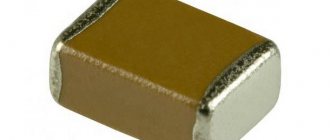
Deciphering the markings of modern ceramic capacitors of domestic and foreign production is a more complex undertaking.
A little about the parameters
It’s worth saying a few words about the last two parameters (power and tolerance). Tolerance in the characteristics of capacitors is the permissible/possible deviation of the capacitance from the specified rating. There are types with a small tolerance - a few percent, and others with a large tolerance - up to 20%. It is not always possible to replace a capacitor with a low tolerance with an analogue in terms of capacity and voltage, but with a higher tolerance. This is only permissible in household appliances. And then, only where the amount of charge is not too critical. But it is better to look for a replacement with a similar tolerance.
| Capacitance tolerance coding | Tolerance % |
| E | 0.005 |
| L | 0.01 |
| P | 0.002 |
| W | 0.005 |
| B | 0.1 |
| C | 0.25 |
| D | 0.5 |
| F | 1 |
| G | 2 |
| H | 2.5 |
| J | 5 |
| K | 10 |
| M | 20 |
| N | 30 |
| Q | -10 … +30 |
| T | -10…+50 |
| S | -20…+50 |
| Z | -20…+80 |
It often happens that a capacitor periodically “flies out” in the same place. According to our logic, we want to replace it with an element with higher voltage. But there may be 2 options here. Firstly: there are voltage surges in the circuit that exceed the rated voltage of the part. Secondly, the reactive power of the capacitor is not taken into account if it operates in high-frequency circuits.
We recommend reading: What are instrumentation and instrumentation systems: definition of the abbreviation, purpose
For the most part, the power parameter is not indicated and can be found in the specification for the part. It is usually used by narrow specialists.
The temperature coefficient may also be indicated - TKE, but it is not set in all cases. It displays the change in capacity depending on the temperature of the element. Usually included if there is a significant dependency. If the changes are minor, they are simply omitted. Many parameters can be easily recognized with a radio element tester.
Abbreviations
The standard version includes permanent (K) and trimmer (CT) capacitors. Variables (CV) are created according to individual orders. Below are individual parameters according to GOST 13 453-68.
Dielectric material:
- B – paper;
- MP – metal/film combination;
- C – mica;
- E – electrolyte;
- K – ceramics.
According to the degree of protection from external influences, a hermetic (G) version and a pressurized housing (O) are distinguished.
Design:
- M – monolith;
- B – barrel;
- D – disk;
- C – sectional option.
Operating mode (current):
- I – pulse;
- U – universal (pulse, constant and variable);
- H – only constant;
- P – variable/constant.
Other features:
- U – capacitor designed to operate in the VHF range;
- M – compact dimensions;
- T – preservation of technical parameters is ensured when the temperature rises;
- B – the product is suitable for installation in high voltage networks.
The standard designation indicates (by position number):
- type of capacitor (K, CT or KP);
- code for dielectric and basic parameters (K10 ceramics for voltage up to 1600 V);
- current operating mode;
- production series or other technological designation.
Additional information:
- You can select products by combined (numeric and alphabetic) color marking;
- Abbreviations are applied to the compact body (instead of 1000uF - 1000m);
- The accuracy class is indicated in Latin font (U is ±);
- The rated voltage (Q-160V) is encoded in the same way.
Why is labeling needed?
The purpose of marking electronic components is to allow them to be accurately identified. Capacitor markings include:
- data on the capacitance of the capacitor - the main characteristic of the element;
- information about the rated voltage at which the device remains operational;
- data on the temperature coefficient of the capacitance, which characterizes the process of changing the capacitance of the capacitor depending on changes in ambient temperature;
- percentage of permissible deviation of the capacity from the nominal value indicated on the device body;
- release date.
For capacitors, when connecting which polarity must be observed, information must be provided that allows the element to be correctly oriented in the electronic circuit.
The marking system for capacitors produced at enterprises that were part of the USSR had fundamental differences from the marking system used at that time by foreign companies.
Code marking, addition
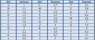
According to IEC standards, in practice there are four ways to encode the nominal capacity.
A. 3-digit marking
The first two digits indicate the capacitance value in pygofarads (pf), the last one indicates the number of zeros. When the capacitor has a capacitance of less than 10 pF, the last digit may be "9". For capacitances less than 1.0 pF, the first digit is “0”. The letter R is used as a decimal point. For example, code 010 is 1.0 pF, code 0R5 is 0.5 pF.
| Code | Capacitance [pF] | Capacitance [nF] | Capacitance [µF] |
| 109 | 1,0 | 0,001 | 0,000001 |
| 159 | 1,5 | 0,0015 | 0,000001 |
| 229 | 2,2 | 0,0022 | 0,000001 |
| 339 | 3,3 | 0,0033 | 0,000001 |
| 479 | 4,7 | 0,0047 | 0,000001 |
| 689 | 6,8 | 0,0068 | 0,000001 |
| 100* | 10 | 0,01 | 0,00001 |
| 150 | 15 | 0,015 | 0,000015 |
| 220 | 22 | 0,022 | 0,000022 |
| 330 | 33 | 0,033 | 0,000033 |
| 470 | 47 | 0,047 | 0,000047 |
| 680 | 68 | 0,068 | 0,000068 |
| 101 | 100 | 0,1 | 0,0001 |
| 151 | 150 | 0,15 | 0,00015 |
| 221 | 220 | 0,22 | 0,00022 |
| 331 | 330 | 0,33 | 0,00033 |
| 471 | 470 | 0,47 | 0,00047 |
| 681 | 680 | 0,68 | 0,00068 |
| 102 | 1000 | 1,0 | 0,001 |
| 152 | 1500 | 1,5 | 0,0015 |
| 222 | 2200 | 2,2 | 0,0022 |
| 332 | 3300 | 3,3 | 0,0033 |
| 472 | 4700 | 4,7 | 0,0047 |
| 682 | 6800 | 6,8 | 0,0068 |
| 103 | 10000 | 10 | 0,01 |
| 153 | 15000 | 15 | 0,015 |
| 223 | 22000 | 22 | 0,022 |
| 333 | 33000 | 33 | 0,033 |
| 473 | 47000 | 47 | 0,047 |
| 683 | 68000 | 68 | 0,068 |
| 104 | 100000 | 100 | 0,1 |
| 154 | 150000 | 150 | 0,15 |
| 224 | 220000 | 220 | 0,22 |
| 334 | 330000 | 330 | 0,33 |
| 474 | 470000 | 470 | 0,47 |
| 684 | 680000 | 680 | 0,68 |
| 105 | 1000000 | 1000 | 1,0 |
* Sometimes the last zero is not indicated.
B. 4-digit marking
4-digit coding options are possible. But even in this case, the last digit indicates the number of zeros, and the first three indicate the capacity in picofarads.
| Code | Capacitance[pF] | Capacitance[nF] | Capacitance[uF] |
| 1622 | 16200 | 16,2 | 0,0162 |
| 4753 | 475000 | 475 | 0,475 |
C. Capacitance marking in microfarads
The letter R may be used instead of the decimal point.
| Code | Capacitance [µF] |
| R1 | 0,1 |
| R47 | 0,47 |
| 1 | 1,0 |
| 4R7 | 4,7 |
| 10 | 10 |
| 100 | 100 |
D. Mixed alphanumeric marking of capacity, tolerance, TKE, operating voltage
Unlike the first three parameters, which are marked in accordance with standards, the operating voltage of different companies has different alphanumeric markings.
| Code | Capacity |
| p10 | 0.1 pF |
| IP5 | 1.5 pF |
| 332p | 332 pF |
| 1NO or 1nO | 1.0 nF |
| 15H or 15n | 15 nF |
| 33H2 or 33n2 | 33.2 nF |
| 590H or 590n | 590 nF |
| m15 | 0.15uF |
| 1m5 | 1.5 µF |
| 33m2 | 33.2 µF |
| 330m | 330 µF |
| 1mO | 1 mF or 1000 μF |
| 10m | 10 mF |
Code marking of electrolytic capacitors for surface mounting
The following coding principles are used by such well-known companies as Hitachi and others. There are three main coding methods:
A. Marking with 2 or 3 characters
The code contains two or three characters (letters or numbers) indicating the operating voltage and rated capacity. Moreover, the letters indicate voltage and capacitance, and the number indicates the multiplier. In the case of a two-digit designation, the operating voltage code is not indicated.
| Code | Capacitance [µF] | Voltage [V] |
| A6 | 1,0 | 16/35 |
| A7 | 10 | 4 |
| AA7 | 10 | 10 |
| AE7 | 15 | 10 |
| AJ6 | 2,2 | 10 |
| AJ7 | 22 | 10 |
| AN6 | 3,3 | 10 |
| AN7 | 33 | 10 |
| AS6 | 4,7 | 10 |
| AW6 | 6,8 | 10 |
| CA7 | 10 | 16 |
| CE6 | 1,5 | 16 |
| CE7 | 15 | 16 |
| CJ6 | 2,2 | 16 |
| CN6 | 3,3 | 16 |
| CS6 | 4,7 | 16 |
| CW6 | 6,8 | 16 |
| DA6 | 1,0 | 20 |
| DA7 | 10 | 20 |
| DE6 | 1,5 | 20 |
| DJ6 | 2,2 | 20 |
| DN6 | 3,3 | 20 |
| DS6 | 4,7 | 20 |
| DW6 | 6,8 | 20 |
| E6 | 1,5 | 10/25 |
| EA6 | 1,0 | 25 |
| EE6 | 1,5 | 25 |
| EJ6 | 2,2 | 25 |
| EN6 | 3,3 | 25 |
| ES6 | 4,7 | 25 |
| EW5 | 0,68 | 25 |
| GA7 | 10 | 4 |
| GE7 | 15 | 4 |
| GJ7 | 22 | 4 |
| GN7 | 33 | 4 |
| GS6 | 4,7 | 4 |
| GS7 | 47 | 4 |
| GW6 | 6,8 | 4 |
| GW7 | 68 | 4 |
| J6 | 2,2 | 6,3/7/20 |
| JA7 | 10 | 6,3/7 |
| JE7 | 15 | 6,3/7 |
| JJ7 | 22 | 6,3/7 |
| JN6 | 3,3 | 6,3/7 |
| JN7 | 33 | 6,3/7 |
| JS6 | 4,7 | 6,3/7 |
| JS7 | 47 | 6,3/7 |
| JW6 | 6,8 | 6,3/7 |
| N5 | 0,33 | 35 |
| N6 | 3,3 | 4/16 |
| S5 | 0,47 | 25/35 |
| VA6 | 1,0 | 35 |
| VE6 | 1,5 | 35 |
| VJ6 | 2,2 | 35 |
| VN6 | 3,3 | 35 |
| VS5 | 0,47 | 35 |
| VW5 | 0,68 | 35 |
| W5 | 0,68 | 20/35 |
We recommend reading: Hall sensor design: principle of operation, application, circuit diagram, connection
B. 4-character marking
The code contains four characters (letters and numbers) indicating the capacity and operating voltage. The first letter indicates the operating voltage, the subsequent digits indicate the nominal capacitance in picofarads (pF), and the last digit indicates the number of zeros. There are 2 options for encoding the capacity: a) the first two digits indicate the nominal value in picofarads, the third - the number of zeros; b) the capacitance is indicated in microfarads, the m sign acts as a decimal point. Below are examples of marking capacitors with a capacity of 4.7 μF and an operating voltage of 10 V.
C. Two-line marking
If the size of the case allows, then the code is located in two lines: the capacitance rating is indicated on the top line, and the operating voltage is indicated on the second line. Capacitance can be indicated directly in microfarads (µF) or in picofarads (pf) indicating the number of zeros (see method B). For example, the first line is 15, the second line is 35V - means that the capacitor has a capacity of 15 uF and an operating voltage of 35 V.
Unit converter
1 mF = 0.001 F. 1 µF = 0.000001 = 10⁻⁶ F. 1 nF = 0.000000001 = 10⁻⁹ F. 1 pF = 0.000000000001 = 10⁻¹² F.
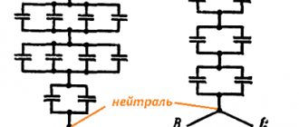
According to Kirchhoff's second rule, the voltage drop V₁
,
V₂
and
V₃
on each of the capacitors in a group of three capacitors connected in series are generally different and the total potential difference
V
is equal to their sum:
By definition of capacitance and taking into account the fact that charge Q
of a group of capacitors connected in series is common to all capacitors, the equivalent capacitance
C
eq of all three capacitors connected in series is defined as
or
For a group of n
of capacitors connected in series, the equivalent capacitance
C
eq is equal to the reciprocal of the sum of the reciprocals of the capacitances of individual capacitors:
or
If there are only two capacitors, then their total capacity is determined by the formula
or
If there are n
capacitors connected in series with capacitance
C
, their equivalent capacitance is
Note that to calculate the total capacitance of several capacitors connected in series, the same formula is used as to calculate the total resistance of resistors connected in parallel.
Note also that the total capacitance of a group of any number of capacitors connected in series will always be less than the capacitance of the smallest capacitor, and adding capacitors to a group always results in a decrease in capacitance.
Capacitors on a printed circuit board
The voltage drop across each capacitor in a group of series-connected capacitors deserves special mention.
If all capacitors in a group have the same rated capacitance, the voltage drop across them will likely be different, since the capacitors will actually have different capacitances and different leakage current.
The capacitor with the smallest capacitance will have the largest voltage drop and will thus be the weakest link in the circuit.
Equalization resistors reduce voltage spread across individual capacitors
To obtain a more uniform voltage distribution, equalizing resistors are included in parallel with the capacitors. These resistors act as voltage dividers, reducing the voltage spread across the individual capacitors. But even with these resistors, you should still choose capacitors with a large operating voltage margin for series connection.
Capacitors connected in parallel
- By definition of capacitance, the equivalent capacitance of a group of capacitors is
- from here
- or
- For a group of n
capacitors connected in parallel - That is, if several capacitors are connected in parallel, their equivalent capacitance is determined by adding the capacitances of all capacitors in the group.
- You may have noticed that capacitors behave in the opposite way to resistors: if resistors are connected in series, their total resistance will always be higher than the resistance of the individual resistors, but in the case of capacitors, exactly the opposite happens.
Capacitors on a printed circuit board
Rules for decoding markings
First, let's look at the digital marking of capacitors. If the device is small, the EIA standard is used to indicate the capacity. If the code contains only two numbers followed by a letter, their value corresponds to the nominal capacity. The third digit in the code represents the zero multiplier. If it is in the range from 0 to 6, then the corresponding number of zeros must be added to the first two digits. Let's say the notation "463" is equal to 46*10 3 .
The units of measurement depend on the size of the device, and for small ones it is picofarads. In other cases, it is customary to use microfarads. When the digital designation is deciphered, you need to move on to the letters. When they are located within the first two characters, one of 2 methods is used:
- The letter “R” replaces the comma - the inscription 3R2 corresponds to a capacitance of 3.2 picofarads.
- The letter "p" is used as a decimal point - p60 corresponds to 0.6 picofarads. The letters "n" and "m" perform a similar task, but correspond to nano- and microfarads.
So, how to choose a capacitor for a single-phase electric motor?
Most often, the value of the total capacitance Srab + Drain (not a separate capacitor) is as follows: 1 µF for every 100 watts.
There are several operating modes for engines of this type:
- Starting capacitor + additional winding (connected during startup). Capacitor capacity: 70 µF per 1 kW of engine power.
- Working capacitor (capacity 23-35 μF) + additional winding, which is connected during the entire operating time.
- Running capacitor + starting capacitor (connected in parallel).
If you are thinking: how to choose a capacitor for a 220V electric motor, you should proceed from the proportions given above. However, it is necessary to monitor the operation and heating of the engine after connecting it. For example, if the unit noticeably heats up in mode with a working capacitor, the capacitance of the latter should be reduced. In general, it is recommended to select capacitors with an operating voltage of 450 V or more.
How to choose a capacitor for an electric motor is a difficult question. To ensure efficient operation of the unit, it is necessary to carefully calculate all parameters and proceed from the specific conditions of its operation and load.