Parallel and series connection of capacitors: methods, rules, formulas
It is not always possible to select a capacitor of the required value.
Very often, novice home craftsmen, having discovered a breakdown of the device, try to independently discover the cause. Having seen a burnt part, they try to find a similar one, and if this fails, they take the device for repair.
In fact, it is not necessary that the indicators coincide. You can use smaller capacitors by connecting them in a circuit. The main thing is to do it right. In this case, 3 goals are achieved at once - the breakdown is eliminated, experience is gained, and family budget funds are saved.
Let's try to figure out what connection methods exist and what tasks the series and parallel connection of capacitors are designed for.
Often it is impossible to do without connecting capacitors into a battery. The main thing is to do it right
Connecting capacitors into a battery: methods of execution
There are 3 connection methods, each of which has its own specific purpose:
- Parallel - performed if it is necessary to increase the capacity while leaving the voltage at the same level.
- Consistent - the opposite effect. The voltage increases, the capacitance decreases.
- Mixed - both capacity and voltage increase.
Now let's look at each of the methods in more detail.
Parallel connection: diagrams, rules
It's actually quite simple. With a parallel connection, the calculation of the total capacitance can be calculated by simply adding all the capacitors. The final formula will look like this: Total = С₁ + С₂ + С₃ + … + Сn . In this case, the voltage on each of their elements will remain unchanged: Vtotal = V₁ = V₂ = V₃ = ... = Vn .
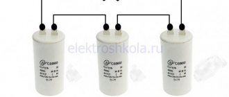
The connection with this connection will look like this:
It turns out that such an installation involves connecting all the capacitor plates to the power points. This method is the most common. But a situation may arise where it is important to increase the voltage. Let's figure out how to do this.
Serial connection: less commonly used method
When using the method of connecting capacitors in series, the voltage in the circuit increases.
It consists of the voltage of all elements and looks like this: Vtotal = V₁ + V₂ + V₃ +…+ Vn .
note
In this case, the capacity changes in the inverse proportion: 1/Comt = 1/С₁ + 1/С₂ + 1/С₃ + … + 1/Сn . Let's look at changes in capacitance and voltage when connected in series using an example.
Given: 3 capacitors with a voltage of 150 V and a capacity of 300 μF. Connecting them in series, we get:
- voltage: 150 + 150 + 150 = 450 V;
- capacity: 1/300 + 1/300 + 1/300 = 1/C = 299 uF.
Externally, such a connection of plates (plates) will look like this:
This connection is made if there is a risk of breakdown of the capacitor dielectric when voltage is applied to the circuit. But there is another way of installation.
Good to know! Series and parallel connections of resistors and capacitors are also used. This is done in order to reduce the voltage supplied to the capacitor and prevent its breakdown. However, it should be borne in mind that the voltage must be sufficient to operate the device itself.
Mixed connection of capacitors: diagram, reasons for the need for use
This connection (also called series-parallel) is used if it is necessary to increase both capacity and voltage. Here, calculating the general parameters is a little more complicated, but not so much that it is impossible for a novice radio amateur to figure it out. First, let's see what such a scheme looks like.
Let's create a calculation algorithm.
- the entire circuit needs to be divided into separate parts, the parameters of which are easy to calculate;
- calculate denominations;
- We calculate the general indicators, as with sequential switching.
Such an algorithm looks like this:
The advantage of mixed inclusion of capacitors in a circuit compared to series or parallel
Mixed connection of capacitors solves problems that parallel and series circuits cannot do. It can be used when connecting electric motors or other equipment; its installation is possible in separate sections. Its installation is much simpler due to the possibility of performing it in separate parts.
Interesting to know! Many radio amateurs consider this method simpler and more acceptable than the previous two. In fact, this is true if you fully understand the algorithm of actions and learn to use it correctly.
Mixed, parallel and series connection of capacitors: what to look for when doing it
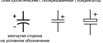
When connecting capacitors, especially electrolytic ones, pay attention to strict polarity. Parallel connection implies a minus/minus connection, and serial connection means a plus/minus connection. All elements must be of the same type - film, ceramic, mica or metal paper.
But this is what the well-known Chinese “inventors” can do - such a capacitor clearly will not last long. Good to know! Failure of capacitors often occurs due to the fault of the manufacturer, which skimps on parts (usually these are Chinese-made devices). Therefore, correctly calculated and assembled elements in the circuit will work much longer. Of course, provided that there is no short circuit in the circuit, in which the operation of capacitors is impossible in principle.
Capacitance calculator for series connection of capacitors
What to do if the required capacity is unknown? Not everyone wants to independently calculate the required capacitor capacity manually, and some simply don’t have the time for this. For the convenience of carrying out such actions, the editors of Seti.
guru invites our dear reader to use an online calculator for calculating capacitors in series connection or calculating capacitance. It is extremely simple to work with. The user only needs to enter the required data in the fields and then click the “Calculate” button.
Programs that contain all the algorithms and formulas for connecting capacitors in series, as well as calculating the required capacity, will instantly produce the required result.
How to calculate the energy of a charged capacitor: we derive the final formula
The first thing you need to do for this is to calculate the force with which the plates are attracted to each other. This can be done using the formula F = q₀ × E, where q₀ is an indicator of the magnitude of the charge, and E is the tension of the plates.
Next, we need an indicator of the tension of the plates, which can be calculated using the formula E = q / (2ε₀S) , where q is the charge, ε₀ is a constant value, S is the area of the plates.
In this case, we obtain a general formula for calculating the force of attraction between two plates: F = q₂ / (2ε₀S) .
The result of our conclusions will be the conclusion of the expression for the energy of a charged capacitor, as W = A = Fd . However, this is not the final formula we need.
We follow further: taking into account the previous information, we have: W = dq₂ / (2ε₀S) . With the capacitance of the capacitor expressed as C = d / (ε₀S) we obtain the result W = q₂ / (2C) .
Features of capacitor protection
Main switches are typically used during emergencies and shut down an entire section of equipment at once. Capacitor units are assembled into sections by parallel connection. Then the main switch will immediately turn off such a “battery”. And other sections of capacitor units will remain in operation. It is important to understand that protective equipment, like the protected equipment, can be grouped using different methods. Depending on convenience and economic feasibility.
Read also: Why you need to overclock your processor ⋆
Lightweight switches are used, as a rule, in control circuits. They are controlled via a relay and increase or decrease the total capacity of capacitor units. Vacuum or SF6 gas is selected as the main switch.
A feature of circuits above 10 kV is the use of single-phase capacitors assembled according to a star or triangle circuit, in each branch of which there is a parallel-series group of capacitors (see figure). If you have products with high operating voltage, it is permissible to do the opposite, to use series-parallel connection. Then the operating voltages of the capacitors are selected so that the number of groups connected one after another is minimal. The voltage on each element naturally increases. For reference: series connection of capacitors.
If you do everything according to the described procedure, if any element of the reactive power compensation circuit fails, the others will continue to operate in a relatively gentle mode. Of course, the circuit parameters need to be monitored, and the operating personnel, according to the methods, check the capacitor units for serviceability. When designing, you need to take into account a small feature:
Read also: What does purple go with?
The more consecutive groups of capacitors there are in the compensation circuit, the more difficult it is for each to ensure uniform voltage distribution. In particular, frequent overloads of a certain segment are possible.
In addition, complex electrical connections are not easy for service personnel to inspect. The ornate design is difficult to install and errors are common. A parallel connection of capacitor blocks for each phase is considered ideal. Then it is easy to install, and the testing procedure is simplified as much as possible.
Series and parallel connection of capacitors
To achieve the required capacitance or for voltages exceeding the rated voltage, capacitors can be connected in series or in parallel. Any complex connection consists of several combinations of serial and parallel connections.
Series connection of capacitors
In series connection of capacitors, the capacitors are connected in such a way that only the outer plates of the first and last capacitor are connected to the current source.
The charge is the same on all plates, but the outer ones are charged from the source, and the inner ones are formed only due to the separation of charges that previously neutralized each other.
In this case, the charge of the capacitors in the battery is less than if each capacitor were connected separately. Consequently, the total capacity of the capacitor bank is less.
The voltages in this section of the circuit are related as follows:
Knowing that the capacitor voltage can be represented in terms of charge and capacitance, we write:
Reducing the expression by Q, we get the familiar formula:
Where does the equivalent capacity of a bank of capacitors connected in series come from:
Parallel connection of capacitors
When capacitors are connected in parallel, the voltage on the plates is the same, but the charges are different.
The amount of total charge received by the capacitors is equal to the sum of the charges of all parallel connected capacitors. In the case of a battery of two capacitors:
Since the capacitor charge
And the voltages on each capacitor are equal, we obtain the following expression for the equivalent capacitance of two parallel-connected capacitors
Example 1
What is the resulting capacitance of 4 capacitors connected in series and in parallel, if it is known that C1 = 10 µF, C2 = 2 µF, C3 = 5 µF, and C4 = 1 µF?
With a series connection, the total capacitance is:
With a parallel connection, the total capacitance is:
Example 2
Determine the resulting capacitance of a group of capacitors connected in series-parallel, if it is known that C1 = 7 µF, C2 = 2 µF, C3 = 1 µF.
First, let's find the total capacitance of the parallel section of the circuit:
Then we find the total capacitance for the entire circuit:
In fact, calculating the total capacitance of capacitors is similar to calculating the total resistance of a circuit in the case of a series or parallel connection, but at the same time, it is the opposite.
We advise you to read: Charging and discharging a capacitor
1 1 1 1 1 1 1 1 1 1 0.00 (0 Votes)
Source: https://electroandi.ru/elektronika/posledovatelnoe-i-parallelnoe-soedinenie-kondensatorov.html
Legend
With the abbreviated system, letters and numbers are applied, where a letter indicates a subclass, a number indicates a group, depending on the dielectric used. The third element indicates the registration number of the product type.
With a full symbol, the parameters and characteristics are indicated in the following sequence:
- symbol of the design of the product;
- rated voltage of the product;
- nominal capacity of the product;
- permissible deviation of capacitance;
- temperature stability of the product container;
- rated reactive power of the product.
Series connection of capacitors: formula:
A series connection refers to cases where two or more elements are in the form of a chain, with each of them connected to the other at only one point. Why are capacitors placed this way? How to do this correctly? What do you need to know? What features does series connection of capacitors have in practice? What is the result formula?
What do you need to know for a correct connection?
Alas, not everything here is as easy to do as it might seem. Many beginners think that if the schematic drawing says that an element of 49 microfarads is needed, then it is enough to simply take it and install it (or replace it with an equivalent one).
But it is difficult to select the necessary parameters even in a professional workshop. And what to do if you don’t have the necessary elements? Let's say there is such a situation: you need a 100 microfarad capacitor, but there are several 47 microfarad capacitors. It is not always possible to install it.
Advice
Go to the radio market for one capacitor? Not necessary. It will be enough to connect a couple of elements. There are two main methods: series and parallel connection of capacitors. That's the first one we'll talk about.
But if we talk about the series connection of the coil and capacitor, then there are no special problems.
Why do they do this?
When such manipulations are carried out with them, the electric charges on the plates of the individual elements will be equal: KE=K1=K2=K3. KE – final capacitance, K – transmitting value of the capacitor.
Why is that? When charges are supplied from the power source to the external plates, a value can be transferred to the internal plates, which is the value of the element with the smallest parameters.
That is, if you take a 3 µF capacitor, and after it connect it to 1 µF, then the end result will be 1 µF. Of course, on the first one you can observe a value of 3 µF.
Electrical capacity
When connecting devices for charge condensation, as a rule, the technician is interested in the electrical capacitance that will result.
Electrical capacity shows the ability of a two-terminal network to accumulate charge and is measured in farads. It may seem that the higher this value, the better, but in practice it is not possible to create all possible containers in the world, moreover, this is often not necessary, since all devices used every day use standard condensation devices.
You can connect several devices for condensation in a circuit, creating one condensing container, and the value of the characteristic value will depend on the type of connection, and there are long-known formulas for its calculation.
Connecting capacitors How to connect capacitors correctly?
Many novice electronics enthusiasts in the process of assembling a homemade device have a question: “How to connect capacitors correctly?”
It would seem why this is necessary, because if the circuit diagram indicates that a 47 microfarad capacitor should be installed in a given place in the circuit, then we take and install the required capacitor. But, you must admit that in the workshop of even an avid electronics engineer there may not be a capacitor with the required rating!
A similar situation may arise when repairing any device. For example, you need an electrolytic capacitor with a capacity of 1000 microfarads, but only 2 - 3 capacitors with a capacity of 470 microfarads are at hand. Should I install a capacitor at 470 microfarads instead of the required 1000? No, this is not always acceptable. So what should we do? Travel several tens of kilometers to the radio market for one capacitor?
How to get out of this situation? You can connect several capacitors and as a result get the capacitance we need. In electronics, there are two ways to connect capacitors: parallel and series.
In reality it looks like this:
Parallel connection
Schematic diagram of parallel connection
Serial connection
Schematic diagram of serial connection
You can also combine parallel and series connection of capacitors. In practice you are unlikely to need this.
How to calculate the total capacitance of connected capacitors?
A few simple formulas will help us with this. Have no doubt, if you work in electronics, these simple formulas will help you out sooner or later.
Total capacitance of parallel connected capacitors:
C1 – capacity of the first capacitor;
C2 – capacity of the second capacitor;
C3 – capacity of the third capacitor;
СN – capacity of the Nth capacitor;
Ctotal is the total capacity of the composite capacitor.
As you can see, when connecting the capacitors in parallel, you just need to add them up!
Attention! All calculations must be made in the same units. If we calculate capacitances in microfarads, then we need to indicate the capacitance C1 , C2 in microfarads. The result will also be obtained in microfarads. This rule must be followed, otherwise mistakes cannot be avoided!
note
To avoid making mistakes when converting microfarads to picofarads or nanofarads, you can use a special table. It indicates prefixes used for short notation and factors with which you can recalculate the values of quantities.
Mixed connection
But, it is worth considering that to connect different capacitors, it is necessary to take into account the network voltage. For each semiconductor, this indicator will differ depending on the capacitance of the element. It follows that individual groups of small-capacity semiconductor biterminals will become larger when charging, and vice versa, a large-sized electrical capacitance will require less charging.
Scheme: mixed connection of capacitors
There is also a mixed connection of two or more capacitors. Here, electrical energy is distributed simultaneously using parallel and series connections of electrolytic cells in a circuit. This circuit has several sections with different connections of condensing two-terminal networks. In other words, on one the circuit is connected in parallel, on the other - in series. This electrical circuit has a number of advantages compared to traditional ones:
- Can be used for any purpose: connecting an electric motor, machine equipment, radio equipment;
- Simple calculation. For installation, the entire circuit is divided into separate sections of the circuit, which are calculated separately;
- The properties of the components do not change regardless of changes in the electromagnetic field or current strength. This is very important when working with opposite two-terminal networks. The capacitance is constant at a constant voltage, but the potential is proportional to the charge;
- If you need to assemble several non-polar semiconductor two-terminal networks from polar ones, then you need to take several single-pole two-terminal networks and connect them in a back-to-back (triangle) manner. Minus to minus, and plus to plus. Thus, by increasing the capacitance, the operating principle of a bipolar semiconductor changes.
Series and parallel connection of capacitors
In practice, bodies are often used that have small (and very small) sizes that can accumulate a large charge while having little potential. Such objects are called capacitors. One of the main characteristics of a capacitor is its capacity.
Having in reserve a set of capacitors with different parameters, you can expand the range of capacitance values and the range of operating voltages if you use their connections.
There are three types of capacitor connections: series, parallel and mixed (parallel and series).
Series connection of capacitors
The series connection of capacitors is shown in Fig. 1
Here (Fig. 1) the positive plate of one capacitor is connected to the negative plate of the next capacitor. With this connection, the plates of adjacent capacitors create a single conductor. All capacitors connected in series on their plates have equal charges. The electrical capacitance of a series connection of capacitors is calculated by the formula:
where is the electrical capacitance of the i-th capacitor.
If the capacitances of the capacitors when connected in series are equal, then the capacitance of their series connection is:
where N is the number of capacitors connected in series. In this case, the maximum voltage (U) that such a bank of capacitors can withstand will be:
where is the maximum voltage of each connection capacitor. When connecting capacitors in series, care must be taken to ensure that no battery capacitor is exposed to a voltage greater than its maximum operating voltage.
Parallel connection of capacitors
A parallel connection of N capacitors is shown in Fig. 2.
When connecting capacitors in parallel, plates with charges of the same sign are connected (plus with plus; minus with minus). As a result of such a connection, one plate of each capacitor has the same potential, for example, and the other. The potential differences on the plates of all capacitors when they are connected in parallel are equal.
When connecting capacitors in parallel, the total capacitance of the connection is calculated as the sum of the capacitances of the individual capacitors:
When connecting capacitors in parallel, the voltage is equal to the lowest operating voltage of the capacitor from the connection in question.
Conclusion
As a result of this lesson, I no longer just point out X7R or X5R types to colleagues or suppliers.
Instead, I list specific batches from specific suppliers that I have tested myself. I also caution clients to double-check specifications when considering alternative manufacturing suppliers to ensure they do not encounter these problems. The main conclusion from this whole story, as you probably guessed, is: “read the datasheets!” Always. With no exceptions. Request additional information if the datasheet does not contain sufficient information. Remember that the designations for ceramic capacitors are X7V, Y5V, etc. They say absolutely nothing about their voltage coefficients. Engineers must double-check the data to know, really know, how the capacitors they use will perform under real-world conditions. So keep in mind, in our mad rush to get smaller and smaller, this is becoming more and more important every day.
Tags
use capacitors in parallel with capacitors connect electrolytic capacitors for Capacitors connecting capacitors connecting capacitors connecting capacitors connecting capacitors connecting capacitors connecting capacitors and parallel connections are recommended in parallel with capacitors Parallel connection of series connection is reduced series connection of capacitors parallel connection of capacitors Parallel connection of capacitors in parallel connection Series connection of capacitors mixed connection of capacitors parallel connection of capacitors Types of connection of capacitors Parallel connection of capacitors and the voltage is divided by the operating voltage .use serial and When connected in series, however SERIAL practically
cover articlenecessary drives source
