Installation of branches in a socket box
The wiring can run inside the walls or on their surface.
The first option is simple to implement, but inferior in aesthetics. Hidden wiring provides for wall finishing after installation. However, when the need arises to repair the electrical network, the walls have to be destroyed. Connecting devices to the power cable must be safe and secure. Each outlet must have a housing to protect it from electric current. Mounted ones have their own box. To install built-in ones, socket boxes are used. They are made of dielectric materials, securely fix the device in the wall, prevent moisture from entering and are fireproof.
Grounding is installed in each socket box; there is enough space for laying wires. This method is considered reliable and guarantees protection. It is indispensable if additional installation of several sockets is necessary. Eliminates large-scale work. It is used for light loads in an apartment or house, under normal conditions.
Connecting a double socket with your own hands
The modern concept of a double socket is not entirely clear. Many of us still perceive such a device as several separate sockets placed close to each other. However, this option is not very aesthetically pleasing, and sometimes also requires expanding the existing niche in the wall to install an additional socket box.
It’s a completely different matter when the double socket is made in the form of a monoblock, and it is quite possible to replace the old prototype installed in the same place. In the worst case, you will have to dismantle the existing installation box to replace it, but if this is done carefully, the process will not lead to a global re-gluing of wallpaper or repainting the entire wall.
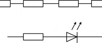
Connection diagram for socket and switch: loop, series, parallel
Let's look at how to connect an outlet or a multi-unit unit. You can connect electrical outlets in parallel via a junction box or using terminals; this method is also called a daisy chain connection. When connecting electrical outlets with a cable, the cable is connected to the first unit of the block, and the cable for the next block is powered from the last. For a daisy chain connection, mandatory independent disconnections of the socket are required. To do this, the conductors are connected to the neutral conductors through terminals or soldering. Zero and phase are connected to the first electrical outlet. A clamp is placed on the grounding wire, from which a grounding wire is supplied to each of the units. To connect the second socket block, you need to connect the phase and working zero from the last unit of the first block, and the ground wire into the compressor.
Now let's look at connecting a conventional single-key switch. To do this, we connect the phase wire to the switch using a clamp marked with an English “L” or an “outward” arrow; we connect the zero to a clamp with an “inward” arrow or the letter “N”. We screw both wires securely. Since grounding is not used in switches, we cut off the excess wire and insulate it.
Another pressing question: “How to connect a switch from an outlet”? To do this, it is better to use a block consisting of an electrical outlet and one or more switches. A new cable is laid from the junction box. One core of the cable carries the phase to the switch, and the other leads the working “zero” to the socket. The remaining conductors pass to the lamps through switches. 3-wire wires (zero, ground and phase) are laid from the junction box to the lamps.
The procedure for installing the loop
Determining the phase with an indicator screwdriver
All work requires a professional approach and compliance with safety precautions. You need to know how to properly connect a group of outlets. Before starting, it is necessary to de-energize the entire apartment in order to disconnect both phase and zero. The absence of voltage is checked with an indicator at the place of work. Installation is carried out in the following sequence.
- Marking and preparing the site.
- Wall chipping.
- Laying the cable from the junction box to the first socket box.
- Preparing wires for jumpers.
- Installation of socket boxes.
- Preparing branches to connect PE conductors.
- Line installation and wire laying.
Correct connection of the socket cable through the connection of wires in the PPE cap - Connection of neutral and phase conductors and grounding conductors.
- Securing the working elements in the socket box and installing the front covers.
The quality of installation depends on the types of contact elements. Models with a flat-spring connection method are considered reliable. In extreme cases, it could be a plate clamped with a bolt. The cable supplied to the socket must protrude beyond the wall surface by no more than 80 mm. If necessary, it should be shortened.
Incorrect connection directly through the terminal contact of the socket leads to its gradual burnout
The cable braid is removed, the wires are separated to the sides. On the left is the phase, on the right is the neutral, in the middle is the ground wire. Their ends are exposed by 10mm using an insulation stripper or knife. The socket has self-clamping spring terminals for easy operation. Insert the sufficiently stripped end of the wire into the hole until it stops.
Then you need to check the reliability of fastening of all wires by pulling. First of all, the leads are packaged, and the entire structure is inserted into the socket box, pre-fixed on the sides with screws. The level is checked for horizontalness, then the screws are finally tightened. The last to be installed is the front panel, the overlay frame.
Sockets can be connected with a cable for low-power electrical equipment. This method is justified if you urgently need to add a couple of additional outlets. The operation of powerful devices requires the installation of a separate output. The amount of energy required for household needs is increasing, and the requirements for the quality of electrical installations and the reliability of sockets are increasing.
Electrical outlet device
Almost any master had to deal with connecting an outlet. At first glance, this procedure is very simple, but there are many nuances hidden beneath it. To prevent a self-connected outlet from becoming a source of problems, you need to understand the principle of its operation. It consists of the following components:
- Decorative overlay with fixed screw.
- Socket box. To fasten the element inside the mounting hole, it has tabs, with the help of which the insert is attached to the hole. The pads, whose contacts are movable, are more difficult to install, but thanks to their design it is possible to adjust the position in tilt and height. It is advisable to choose models with two-toothed feet. Compared to single-tooth ones, they are much more reliable.
- Contact box assembled. The terminals can be connected in various ways, such as with contact screws directly, or they can be made as a single unit. Two contacts, neutral and phase, as well as grounding which is located separately.
Installing an outlet block
To work you need a certain set of tools:
- voltage indicator;
- level;
- universal screwdriver;
- pliers;
- pencil and construction knife;
- press pliers;
- thermotube;
- hammer drill
First, the wiring diagram is performed. It indicates the location of distribution boxes, sockets, and switches. Mark the route along which the wires will go. They must be positioned strictly vertically and horizontally, and have no more than one bend at a right angle. The depth of the channels is up to 2.5 cm, width 3. The length from the box to the outlet is no more than 3 meters. The diagram should be saved so that during the next repair you do not get caught in the wire.
The most labor-intensive work is gating walls. It is more convenient to do this with a special tool, but you can get by with improvised means - a hammer, a chisel, a grinder, a drill with an 8-10mm Pobedit drill bit. It should be held perpendicular to the wall and operated at low speeds. Cool the drill periodically in water.
Next, holes are made for the socket boxes. The sleeves are mounted on alabaster or plaster. To prevent the solution from hardening quickly, you can add PVA glue to the water. The standard box has a depth of 45 mm. Everything you need can easily fit into the socket box.
Types of devices and their features
There are quite a lot of varieties of plug sockets and blocks. Each type has its own design features and purpose.
- Hidden devices are mounted directly into the wall - in special socket boxes.
- Open devices are produced for those apartments where the electrical wiring is not hidden in the wall.
- Retractable socket blocks are mounted in a table or other furniture. Their convenience lies in the fact that after use, the devices can be easily hidden from prying eyes and playful children’s hands.
The devices differ in the method of clamping the contacts. It comes in screw and spring types. In the first case, the conductor is fixed with a screw, in the second - with a spring. The latter are more reliable, but they are not so easy to find on sale. The devices are fixed to the walls in three ways - claws with jagged edges, self-tapping screws or a special plate - a support that facilitates both installation and dismantling of the socket.
In addition to conventional, inexpensive devices, there are models equipped with grounding contacts. These petals are located in the upper and lower parts, and a grounding wire is attached to them. To ensure safety, sockets are equipped with curtains or protective covers.
Main popular types
These include:
- type “C”, it has 2 contacts - phase and zero, usually purchased if intended for low or medium power equipment;
- type “F”, in addition to the traditional pair, is equipped with one more contact - a grounding one; these sockets are becoming more popular, since a grounding loop has become the norm for apartments in new buildings;
- Type “E”, which differs from the previous one only in the shape of the grounding contact, is a pin, the same as the elements of the socket plug.
The last type is less common than the others, since it is less convenient to use: turning the plug 180° with such a socket is impossible.
The security of the case is the next difference between the models. The degree of security is indicated by the IP index and a two-digit number following these letters. The first number indicates the class of protection against dust and solids, the second - against moisture.
- For ordinary living rooms, IP22 or IP33 class models are sufficient.
- It is recommended to buy IP43 for children, as these sockets are equipped with covers/curtains that block the sockets when the equipment is not in use.
- IP44 is the minimum required for bathrooms, kitchens, and baths. Not only strong humidity, but also splashes of water can pose a threat. They are suitable for installation in basements without heating.
Installing an outlet on an open balcony is a sufficient reason to purchase a product with a higher degree of protection, this is at least IP55.
Problems on parallel connection of conductors with solutions
Formulas used in the lessons “Problems on parallel connection of conductors”
Problem No. 1. Two conductors with a resistance of 200 Ohms and 300 Ohms are connected in parallel. Determine the total resistance of the circuit section.
Problem No. 2. Two resistors are connected in parallel. The current in the first resistor is 0.5 A, in the second - 1 A. The resistance of the first resistor is 18 Ohms. Determine the current strength throughout the entire circuit and the resistance of the second resistor.
Problem No. 3. Two lamps are connected in parallel. The voltage on the first lamp is 220 V, the current in it is 0.5 A. The current in the circuit is 2.6 A. Determine the current in the second lamp and the resistance of each lamp.
Task No. 4. Determine the readings of the ammeter and voltmeter if a current of 0.1 A flows through a conductor with resistance R1. Neglect the resistance of the ammeter and supply wires. Assume that the resistance of the voltmeter is much greater than the resistance of the conductors under consideration.
Problem No. 5. Three electric lamps are connected in parallel in the battery circuit. Draw a circuit for turning on two switches so that one controls two lamps at the same time, and the other controls one third lamp.
Answer:
Problem No. 6. The lamps and ammeter are turned on as shown in the figure. How many times do the ammeter readings differ between open and closed switches? The lamp resistances are the same. The voltage is maintained constant.
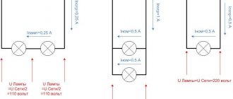
Problem No. 7. The voltage in the network is 120 V. The resistance of each of the two electric lamps connected to this network is 240 Ohms. Determine the current in each lamp when they are connected in series and in parallel.
Problem No. 8. Two electric lamps are connected in parallel at a voltage of 220 V. Determine the current strength in each lamp and in the supply circuit if the resistance of one lamp is 1000 Ohms and the other is 488 Ohms.
Problem No. 9. Two identical lamps are connected to the circuit. When the rheostat slider is positioned at point B, ammeter A1 shows a current of 0.4 A. What do ammeters A and A2 show? Will the ammeter readings change when the slider moves to point A?
Problem No. 10. OGE Two series-connected resistors were connected to a network with a voltage of U = 24 V. In this case, the current strength was I1 = 0.6 A. When the resistors were connected in parallel, the total current strength became equal to I2 = 3.2 A. Determine the resistance of the resistors.
Problem No. 11. Unified State Examination A milliammeter, designed to measure currents up to IA = 25 mA, having an internal resistance of RA = 10 Ohms, must be used as an ammeter to measure currents up to I = 5 A. What resistance should the shunt have?
This is a summary on the topic “Tasks on Parallel Connection of Conductors.” Choose what to do next:
- Go to topic: PROBLEMS on the work of electric current
- View the summary on the topic Connecting conductors
- Return to the list of Physics notes.
- Test your knowledge of Physics.
How to properly connect an outlet - detailed instructions
For single and double sockets this is not difficult to do (installing such sockets involves drilling one hole in the wall), but installing a triple socket will be more difficult. It is necessary to accurately mark the centers of the sockets, taking into account the distance between them.
If it is necessary to lay wiring in a new location, straight lines (horizontal and vertical) are drawn on the wall. Curvilinear and oblique routes are not allowed: this will make it difficult to find the location of damage and repair the wiring in the future.
Required tools and materials
To work in a house with brick and concrete walls, you must have at your disposal:
- perforator;
- a special attachment – a crown with a diameter of 70 mm with carbide cutters;
- voltage indicator;
- chisel;
- hammer;
- straight and figured screwdriver;
- narrow and medium spatulas.
To carry out electrical wiring, it is necessary to replace the old aluminum cable with a new copper cable. The core insulation is double, the cross-section (for the socket group) is 2.5 mm². It is recommended to use cable type GDP-2×2.5 or GDP-3×2.5. In addition, you will need socket boxes (plastic cups with a diameter of 67 mm), alabaster for fixing them and sockets. The latter are chosen according to personal preferences and the color of the front panel: it can be combined with the color of the finishing material for the walls.
Wall chipping
In order not to make wide grooves and avoid cleaning up large amounts of construction waste, you can use the following method when grating walls.
It is convenient for laying single cables, which most often has to be done when installing sockets. It is necessary to use a grinder to make a cut of the required depth. In this case, during the cutting process, the “diamond” wheel should be given wave-like movements: this will slightly widen the groove. In the places where the cut turns (that is, in the corners), widen the groove with a chisel and hammer.
A flat three- or two-core cable of the GDP type fits well into a groove made in this way due to its flat cross-section. At the same time, there is practically no need to “freeze” it with alabaster solution: the cable will stick well to the wall. After laying it, the wall is leveled with gypsum mortar using a medium-width spatula.
Before starting electrical installation work, use the switch located in the switchboard to turn off the power supply. You need to check for voltage at the terminals.
How to connect a grounded outlet
To avoid problems, you must first make the correct wiring connections in the installation box.
It should be remembered that the phase wire (usually the insulation color is brown, black or red) must be connected to the twisted phase wires. It is determined by a voltage indicator. Neutral wire (blue, white) - with neutral, “ground” (yellow, yellow-green) - with grounded wire. Now about how to connect a grounded outlet. An error can be life-threatening: connecting the phase wire to the ground terminal will lead to voltage appearing on the body of the household appliance. To avoid this, you need to know the location of the socket terminals. "Ground" is connected to the central terminal. The remaining two terminals have a phase wire and a neutral wire (they can be swapped).
Grounding is necessary for safety: it will prevent electric shock to a person if current leaks into the housing of household appliances. Therefore, the “ground” core of the cable connected to the socket must be connected at the other end to the “ground” cores of the cables laid from the switchboard at the entrance.
How to connect a double socket
There are no special differences in the installation of such an outlet, since it will also have three terminals, like a single one. The only difference is the orientation of the housing and the plug holes. Those installed vertically may differ in appearance from those installed horizontally. The installation method does not affect anything and is chosen based on personal wishes.
The socket is fixed in the socket box, “frozen” using alabaster (applied with a spatula), and then its front panel is installed.
«>
Not yet!
Installing an outlet block
To work you need a certain set of tools:
- voltage indicator;
- level;
- universal screwdriver;
- pliers;
- pencil and construction knife;
- press pliers;
- thermotube;
- hammer drill
First, the wiring diagram is performed. It indicates the location of distribution boxes, sockets, and switches. Mark the route along which the wires will go. They must be positioned strictly vertically and horizontally, and have no more than one bend at a right angle. The depth of the channels is up to 2.5 cm, width 3. The length from the box to the outlet is no more than 3 meters. The diagram should be saved so that during the next repair you do not get caught in the wire.
The most labor-intensive work is gating walls. It is more convenient to do this with a special tool, but you can get by with improvised means - a hammer, a chisel, a grinder, a drill with an 8-10mm Pobedit drill bit. It should be held perpendicular to the wall and operated at low speeds. Cool the drill periodically in water.
Next, holes are made for the socket boxes. The sleeves are mounted on alabaster or plaster. To prevent the solution from hardening quickly, you can add PVA glue to the water. The standard box has a depth of 45 mm. Everything you need can easily fit into the socket box.
Mixed connection and grounding in series connection
If you decide to use a series connection of sockets, you can strengthen the overall design by using a mixed method. The essence of the method is as follows:
- A central cable is connected to the distribution box from the common panel board.
- In the preliminary wiring plan, the most distant point of access to power is selected.
- The selected outlet is connected from the distribution box cable.
- The rest are powered from this device.
This method increases the reliability of the network. If an outlet fails, the others continue to work. Disabling the entire system is possible only in the event of a malfunction of the main cable, twisted in the junction box.
Grounding is a must. With a serial connection, if a wire burns out at one point, the rest are left without protection. The optimal way to connect sockets to each other for grounding is mixed. The main cable is fixed under the ceiling, then branches are made for each access point.
This technique has disadvantages - the large length of the wires used, the need to install several junction boxes (for each branch). To know for sure whether high-power devices can be connected to the network, it is necessary to calculate the voltage before the cable wiring stage. An accurate calculation will help you choose how to connect the sockets in the end - in series, parallel or mixed.
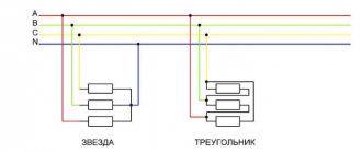
Combined method
In some cases, it is necessary to simultaneously increase the capacity and voltage of the battery. For this, two combined connection methods are used:
- First, several batteries are connected in series. In this way, the required operating voltage is achieved. At the second stage, parallel switching of several batteries obtained by connecting batteries in series is carried out. Several series circuits are created to achieve the required capacity.
- The second method involves parallel switching batteries with the required capacity, after which they are connected in series to achieve the required current.
The combined method is used extremely rarely, as it involves the use of several power sources
When choosing the most suitable batteries, attention is paid to their technical condition, capacity and voltage of the generated current.
Power connection procedure
To properly assemble the socket and connect, follow the following instructions:
- All work must begin with de-energizing the power line. To do this, turn off the circuit breaker in the distribution panel to the desired line if the installation is carried out on an existing wire.
- Using a test lamp or multimeter, we make sure that there is no voltage on the wire that will be connected.
- Stripping the wire. The cable laid to connect the socket, and which has already been routed through the socket box, needs to be prepared for connection. To do this, remove the wire insulation at a distance of 12-15 centimeters, trying not to damage the main insulation of the cores.
- To connect the outlet itself, we connect the bare wires to the contacts. For better contact, we twist 4-6 millimeters of the core into a ring and put it on the clamping screw of the terminal.
- The socket is installed in the mounting hole after all wires are connected. Distortions are unacceptable. The wires must be carefully laid deep into the socket box and secured with clamping paws.
- Install the cover.
Preparation
The ground wire is always yellow-green. Never use it for other purposes. Phase wire - white, red, brown; zero - blue, black. Unfortunately, some electricians adhere to other traditions. In old Soviet houses, generally all the wires are white. It will be convenient for you if the neutral and phase wires are located equally on all sockets. For example, the neutral wire is always below or to the left.
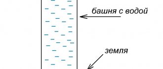
It is customary to place the socket so that the contacts are at the bottom. This makes some sense: in the event of a roof leak, water flowing down the wires will collect in the form of drops on the bend below and will not immediately reach the live contacts.
We begin connecting the outlet by preparing:
- tools (screwdriver, indicator screwdriver, long-nose pliers, wire cutters, possibly a crimping tool (crimper, press pliers), building level);
- consumables: suitable wires, terminal blocks, possibly sleeves or cable terminals;
- flashlight.
Select the exact location for attaching the socket. It is impossible to solve this scientifically, only for reasons of convenience and possible movements of the sofa, table, cabinet... We mark the places for the mounting screws. Construction level - to help. However, you can get by with a modern smartphone with a suitable downloaded program.
In our case, we now need to cut the wire in the right place. We estimate the length for the bend and 1 cm for the terminal. Let's have a snack. (Measure seven times - cut once!) We strip the wire from the top braid, We strip the ends of the wires by 1 cm. (The photo is incorrect - the ends are too short.) This is quite convenient to do with a stationery knife. You can extend the blade just to the thickness of the insulation
and do not damage the wire. A special tool is, of course, convenient, but it is only necessary for professionals for daily work.
Stripping the wire with a special tool
We bend. It is more convenient to work with a soft multi-core wire, and more reliable with a thick single-core wire. The example uses copper wire with a cross section of 2.5 square millimeters.
How to properly connect an outlet
Not every home craftsman, even if he has some experience in performing repair work, knows how to connect the outlet correctly to avoid problems such as short circuits or power overloads.
On the one hand, such work does not take much time and does not require a large amount of specialized knowledge, on the other hand, failure to comply with the basic rules and installation features can lead to a fire hazard. Moreover, in a modern apartment and private house quite powerful equipment can be installed (from an electric kettle to an electric boiler).
Increasing loads lead to the need to choose the right outlet and decide on its connection diagram (if necessary, providing grounding).
Compliance with safety precautions when installing sockets
Work with electricity is classified as dangerous. Even low voltage leads to burns, injuries and other unpleasant consequences. Compliance with safety precautions:
- de-energize the room in which the work is being carried out;
- check the area before starting with a special device (you can plug the device into the network);
- use rubber gloves and equipment with rubberized handles;
- when “increasing” the length, it is not enough to twist the wires; soldering is required;
- contact with connected bare cables is not allowed;
- the excess should not “stick out” - it is shortened and placed in the wall;
- check whether the devices are suitable for the current and voltage levels used.
Open and closed wiring
The difference between the methods is noticeable to the naked eye. The closed wiring is located inside the wall, for which grooves (grooves) are punched or cut into it, in which the connecting wire is hidden under a layer of putty. Open wiring is laid along the surface of the wall, on which it is held in special fasteners or laid in plastic guides - cable channels.
Accordingly, if you can see the wires that fit into the outlet, then the wiring is of an open type. Otherwise, closed wiring is used, for the installation of which the walls were cut.
These two methods of connecting an outlet can be combined with each other - if the old points are connected in a closed way, then nothing prevents you from connecting a new one in an open way. There is only one choice - in wooden houses the socket can be connected exclusively in an open way, just like all other electrical wiring.
Open wiring - advantages and disadvantages
An analogy with the most common extension cord (surge protector), which is essentially an additional branch of the electrical network, but is connected not to a junction box, but to an outlet, will help you understand why open wiring is good.
Advantages:
- You don't have to cut the wall to install a new outlet. This is especially true for those premises that have already been renovated.
- Installation does not require tools such as a wall chaser or a hammer drill.
- In the event of a breakdown, you don’t have to open the wall - all the wiring is in front of your eyes.
- Installation speed. Even after all the work has been completed, adding another point to the existing wiring is a matter of several minutes.
- If desired, you can quickly completely change the wiring - ideal for temporary connection schemes.
Flaws:
- There is a high probability of external influence on the wiring - children, pets, you can simply accidentally hook it. This disadvantage is mitigated by laying wires in cable channels.
- Exposed wires spoil the entire interior of the room. True, it all depends on the design abilities of the owner of the room - cable channels will fit perfectly into modern design solutions, and if the room is made in a retro style, then special wires and other accessories are produced for this.
- The need to purchase special fasteners, even if cable ducts are not used - in wooden houses, open wiring should be laid at a distance of 0.5-1 cm from the wall surface. Wires are often laid inside iron pipes - all these requirements are aimed at increasing the safety of using open electrical wiring.
As a result, this connection method justifies itself if for some reason there is no point in laying the wires to the outlet inside the wall. Besides the fact that the wiring will be visible, there will be no differences in the operation of the outlet.
Hidden wiring - pros and cons
Despite some significant disadvantages, it is used almost everywhere - the advantages of its use still outweigh.
Advantages:
- The wires to the socket fit into the wall, so wallpaper or other finishing can be done freely on the outside.
- Meets all fire safety requirements (in concrete buildings) - even if a short circuit occurs, there is no fear of a fire from the wires in the wall.
- There is a very low probability of damage to the wiring - it can only be damaged when drilling walls.
Flaws:
- For installation you need to cut the walls.
- It is difficult to carry out repair work.
- If the walls are finished, then after installing an additional outlet you will have to redo it.
The disadvantages are leveled out by preliminary calculations - if you plan in advance where and which block of sockets should be installed, then problems usually do not arise in the future.
Advantages and disadvantages
The final version of the wiring diagram
To determine the optimal connection diagram for sockets and switches, it is necessary to prepare a wiring plan, calculate the number of devices and the possible maximum power. At the same time, in newly built buildings it is necessary to plan future possibilities without unnecessary modesty: an additional TV, the purchase of a separate freezer, and the like.
Based on the data received, the connection type is selected. The advantages of the sequential method include:
- simple connection system and circuit assembly;
- the ability to adjust the voltage level, make it less;
- You can use one fuse per circuit.
Examination
We screw the socket cover, checking the horizontal position using a building level. We turn on the main switch. We check first on a table lamp, then on an iron. If you hear at least some sounds from the socket when the iron is turned on, then double-check and re-tighten all connections after turning off the main switch!
Of all the electrical switching devices that modern people encounter, the most common are sockets and switches. Thanks to the ongoing transition of the planet to energy-saving lamps (gas-discharge and diode), the current load on switches is constantly decreasing.
But the load on the sockets, on the contrary, increases. The operation of powerful vacuum cleaners, washing machines with a water heating function, irons, electric kettles, etc. leads to the fact that the current consumption reaches several tens of amperes. And all this load falls on the sockets.
The main function of sockets is to create reliable contact with the plug of the connected device. No matter how powerful the device is, the contact point between the terminal and the plug should not heat up, much less melt. Otherwise, a fire with all its terrible consequences is possible.
In addition, the design of the socket must prevent accidental contact with current-carrying wires and parts. The conclusion from all of the above is that in order to avoid all kinds of troubles, you need to purchase high-quality sockets and connect them in compliance with the necessary rules. In this article we will look at how to execute placed in one module.
Connection methods
Ways to connect sockets
Before connecting many power outlets in a row, it is important to understand the existing methods of connecting them. Depending on the order of switching of individual conductors, the following options are distinguished:
- Parallel connection, in which the sockets must be connected in a star.
- A serial connection, otherwise called a “loop”.
- Combined connection using a loop and a star.
- Ring connection.
Each of the listed methods is selected depending on the architecture of the room and considerations of saving on installation products. A parallel star connection is convenient when distributing the power supply network from a single center (distribution board, for example).
The sequential method (or loop) is used when a whole series of sockets installed one after another is turned on on a given line. The individual contacts (phase and neutral) are connected to each other in parallel; the method is called serial only because of the order in which the socket nodes are located.
When combined, in separate areas, the products are installed in a row, after which a “star” is built from one of them.
Types of triple sockets
They are distinguished based on their shape, structure and size:
- internal (installed in case of hidden wiring);
- external (have increased security and a built-in safety cover);
- built into the wall and overhead.
Modern options additionally include the following types:
- with grounding;
- with no grounding;
- with a safety shutdown (the device turns off when there is a wire short circuit).
The devices can be produced individually (set sockets), each with a rated current of 16 A. To make a triple one out of them, you need to install three separate housings. For greater aesthetics, they can be united by a common external frame. It is purchased separately. To avoid mistakes, it is better to purchase everything at once, since the contours of the frame and rosette panels may not match.
It is recommended to purchase products with square outlines of the internal area of the front panel. These are more universal.