The popularity of the optocoupler based on the pc817 transistor is very high. It is included in almost any electroplated switching power supply with feedback.
The device has a very convenient body. The distance between the leads is 2.54 mm, the rows are spaced 7.62 mm apart.
The main manufacturer of PC817 is Sharp; other electronics factories produce PC817 analogues. By the way, when repairing various electronics, people often first come across substitutes, for example, SFH618 from Siemens or TLP521-1 from Toshiba. There are also double and triple versions of the original: PC827 and PC837.
But it is more profitable to use not a multi-channel substitute, but a certain number of PC817.
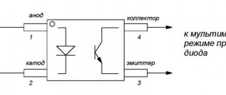
PC817 connection diagram
It is common, as for all transistor optocouplers. The input current must be limited. You can use a resistor for this. The output current must also not be exceeded.
Pc817 connection circuit 372 can be seen in the figure:
PC817 specifications in Russian
PC817 LED parameters:
- Forward current - 50 mA.
- The maximum forward current is 1 A.
- The voltage in the opposite direction is 6 V.
- Dissipated power - 70 MW.
Parameters of phototransistor PC817
Its parameters are as follows:
- The voltage between collector and emitter is 35 V.
- Emitter-collector - 6 V.
- Collector current - 50 mA.
- Dissipated collector power - 150 mW.
We must not forget about one more important parameter. It is called the current transfer ratio, CTR. Its unit of measurement is %. In the optocoupler designation in the pc817 datasheet, it corresponds to the letter following the main code, as in other pc817 optocouplers and semiconductors.
Scope of application of the device
They are used in a variety of fields:
- As elements of galvanic isolation, optocouplers are used: to connect equipment units between which there is a significant potential difference; to protect the input circuits of measuring devices from interference and interference.
- Another important area of application for optocouplers is optical, non-contact control of high-current and high-voltage circuits. Launch of powerful thyristors, triacs, control of electromechanical relay devices. Switching power supplies.
- The creation of “long” optocouplers (devices with an extended flexible fiber-optic light guide) opened up a completely new direction for the use of optocoupler products – communication over short distances.
- Various optocouplers are also used in radio engineering circuits for modulation, automatic gain control and others.
- Impact through the optical channel is used here to bring the circuit to the optimal operating mode, for contactless mode adjustment.
- The ability to change the properties of the optical channel under various external influences on it makes it possible to create a whole series of optocoupler sensors: these are sensors for humidity and gas contamination, sensors for the presence of a particular liquid in the volume, sensors for the cleanliness of the surface treatment of an object, and the speed of its movement.
- The versatility of optocouplers as elements of galvanic isolation and contactless control, the diversity and uniqueness of many other functions are the reason that the scope of optocoupler applications has become computer technology, automation, communications and radio equipment, automated control systems, measuring equipment, control and regulation systems, medical electronics, devices for visual display of information.
View of the optocoupler from different sides.
Advantages of optocouplers
- the ability to provide galvanic isolation between input and output;
- for optocouplers there are no fundamental physical or design restrictions on achieving arbitrarily high voltages and decoupling resistances and arbitrarily small throughput capacitance;
- the possibility of implementing contactless optical control of electronic objects and the resulting diversity and flexibility of design solutions for control circuits;
- unidirectional propagation of information along the optical channel, absence of feedback from the receiver to the emitter;
- wide frequency bandwidth of the optocoupler, no limitation from low frequencies;
- the possibility of transmitting both a pulse signal and a constant component via an optocoupler circuit;
- the ability to control the output signal of the optocoupler by influencing the material of the optical channel and the resulting possibility of creating a variety of sensors, as well as a variety of devices for transmitting information;
- the possibility of creating functional microelectronic devices with photodetectors, the characteristics of which, when illuminated, change according to a complex given law;
- the immunity of optical communication channels to the effects of electromagnetic fields, which makes them protected from interference and information leakage, and also eliminates mutual interference;
- physical, design and technological compatibility with other semiconductor and radio-electronic devices.
It will be interesting➡ Marking of different types of diodes
Disadvantages of optocouplers
- significant power consumption due to the need for double energy conversion (electricity - light - electricity) and the low efficiency of these transitions;
- increased sensitivity of parameters and characteristics to the effects of elevated temperature and penetrating radiation;
- temporary degradation of optocoupler parameters;
- a relatively high level of self-noise, due, like the two previous disadvantages, to the peculiarities of the physics of LEDs;
- the complexity of implementing feedback caused by electrical isolation of the input and output circuits;
- design and technological imperfection associated with the use of hybrid non-planar technology, with the need to combine several individual crystals from different semiconductors located in different planes in one device.
Optocoupler structure
Optocoupler tester
Radio amateur forums often contain the opinion that since the element is inexpensive, then why is a pc817 test needed? It is enough just to change it on time.
In fact, everything is not quite like that. You need to understand whether the optocoupler has burned out or not in order to conclude whether anything else has been damaged. It happens that new optocouplers burn out because they have a manufacturing defect.
How to test pc817? To do this, ring the light diode using a tester. First, find out if there is a short circuit in the transistor. Afterwards, pass current through the light diode and make sure the transistor opens.
You can create a simple device for testing optocouplers at home. For this you will need:
- LEDs - 2 pieces.
- Buttons - 2 pieces
- Resistors - 2 pieces.
Light diodes must correspond to a current strength of 5 to 20 mA and a voltage of approximately 2 V. In this case, the two resistors should have a resistance of around 300 V.
The tester's power source is a USB port with a voltage of 5 V. But you can also use 3-4 2A batteries. 9-12 V batteries or a power source with the same voltage will also work. Only here you will have to recalculate the resistances of the two resistors.
Now let's look at how an optocoupler works, based on various experiments.
Solid State Relay Example
Let's say we need a microcontroller with only a +5V digital output port signal to control a 120VAC, 600W heating element. We could use a MOC 3020 opto-triation isolator for this, but the internal triac can only carry a maximum current (I TSM) of 1A peak at the peak of a 120V AC source, so an additional switching triac must also be used.
First let's look at the input characteristics of the MOC 3020 opto-isolator (other opto-triacs are available). The opto-isolator specification tells us that the forward voltage (VF) of the input LED drop is 1.2V, and the maximum forward current (IF) is 50mA.
The LED requires about 10mA to be able to glow brightly enough up to a maximum of 50mA. However, the digital output port of the microcontroller can output a maximum of 30 mA. Then the required current is somewhere between 10 and 30 milliamps. Hence:
Thus, a resistor can be used to limit the series current with a value between 126 and 380 ohms. Since the digital output port is always switched to +5V and to reduce power dissipation through the optocoupler LED, we will choose a preferred resistance value of 240 ohms. This gives the LED forward current less than 16 mA. For this example, any preferred resistor value between 150 ohms and 330 ohms will do.
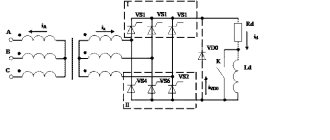
The heating element load is 600 W. Using 120 VAC will give us a load current of 5 amps (I = P/V). Since we want to control this load current in both half cycles (all 4 quadrants) of the AC waveform, we will need a mains switching triac.
The BTA06 is a 600V 6 amp triac (IT (RMS)) suitable for general/on/off switching AC loads, but any similar triac rated 6-8 amps will do. Additionally, this switching triac requires only 50 mA of gate drive to trigger conduction, which is much less than the 1 A maximum of the MOC 3020 opto-isolator.
Note that the opto-isolator triac output turned on at the peak value (90 o ) of the 120 VAC rms supply voltage. This peak voltage has the value: 120 x 1.414 = 170Vpk. If the maximum current of the opto-triacs (I TSM) is 1 A, then the minimum value of the required series resistance is 170/1 = 170 ohms or 180 ohms to the nearest preferred value. This 180 ohm value will protect the output triac of the optocoupler as well as the gate of the BTA06 triac when powered at 120 VAC.
If the opto-isolator triac is turned on at the zero crossing value (0 o ) of the 120 V rms AC supply voltage, then the minimum voltage required to supply the required 50 mA gate drive current to force the switching triac into conduction will be: 180 ohms x 50 mA = 9.0 volt. The triac then fires when the Gate-to-MT1 sine wave voltage exceeds 9 volts.
So the minimum voltage required after the zero crossing point of the AC waveform should be 9 volts, and the power dissipation in this series gate resistor is very small, so it is safe to use a 0.5 ohm resistor with a resistance of 0.5 ohms and nominal 0.5 W. Consider the diagram below.
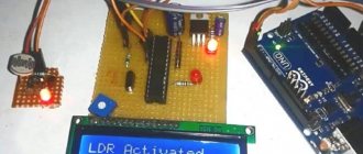
Optocoupler research
To carry out the experiment we will need several devices:
- Oscilloscope.
- Generator.
- Multimeter (2 pieces).
- Bread board.
A signal of a certain type must be supplied to the input of the optocoupler. When leaving, it must be studied with the specified instruments.
The essence of the first test is that you need to apply a linearly increasing voltage. Its source is the power supply with a step of 0.1 V. Measurement is made using digital multimeters near the input and output.
Afterwards, the same procedure is carried out with the participation of an oscilloscope and a generator. A signal is generated there, the amplitude of which is 5 V.
What is an optocoupler
This is a single-channel device, its optical channel is closed. It consists of a light diode and a photographic transistor, which are housed in an SMD package. They are usually located in most switching power supplies in a separate circuit where feedback is applied. Galvanic isolation in such pc817 circuits must be ideal.
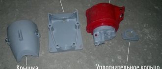
Device Description
The emitter - a packageless LED - is usually placed in the upper part of a metal case, and in the lower part - on a crystal holder - a crystal of a silicon photodetector, for example a photothyristor, is strengthened. The entire space between the LED and the photothyristor is filled with a hardening transparent mass. This fill is covered with a layer that reflects light rays inward, which prevents the scattering of light beyond the working area. The design of the resistor optocoupler differs little from the one described.
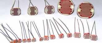
Here, in the upper part of the metal body there is a subminiature incandescent lamp, and in the lower part there is a photoresistor based on cadmium selenide. The photoresistor is made separately, on a thin glass-ceramic substrate. A film of semiconductor material, cadmium selenide, is sprayed onto it, and then forming electrodes made of a conductive material (for example, aluminum) are sprayed onto it. The output terminals are welded to the electrodes. A rigid connection between the lamp and the substrate is ensured by a hardened transparent mass. The holes in the housing for the optocoupler leads are filled with glass. The sealed connection between the lid and the base of the housing is ensured by welding.
The current-voltage characteristic (volt-ampere characteristic) of a thyristor optocoupler is approximately the same as that of a single thyristor. In the absence of input current (I=0 - dark characteristic), the photothyristor can only turn on at a very high value of the forward voltage applied to it (800...1000 V). Since in practice the application of such a large voltage is unacceptable, this curve has a purely theoretical meaning.
This is interesting! All about semiconductor diodes.
If a direct operating voltage is applied to the photothyristor (from 50 to 400 V, depending on the type of optocoupler), the device can only be turned on when an input current is supplied, which is now the control current. The turn-on speed of the optocoupler depends on the value of the input current. Typical switching times t=5…10 µs. The turn-off time of the optocoupler is associated with the process of resorption of minority current carriers in the junctions of the photothyristor and depends only on the value of the flowing output current. The actual value of the shutdown time is in the range of 10...50 µs.
It will be interesting➡ What is a Zener Diode
The maximum and operating output current of a photoresistor optocoupler decreases sharply when the ambient temperature increases above 40 degrees Celsius. The output resistance of this optocoupler remains constant up to an input current of 4 mA, and with a further increase in the input current (when the brightness of the incandescent lamp begins to increase) it decreases sharply. In addition to those described above, there are optocouplers with the so-called open optical channel. Here the illuminator is an infrared LED, and the photodetector can be a photoresistor, photodiode or phototransistor.
The difference between this optocoupler is that its radiation goes out, is reflected from some external object and returns to the optocoupler, to the photodetector. In such an optocoupler, the output current can be controlled not only by the input current, but also by changing the position of the external reflecting surface. In optocouplers with an open optical channel, the optical axes of the emitter and receiver are located either parallel or at a slight angle. There are designs of similar optocouplers with a coaxial arrangement of optical axes. Such devices are called optochoppers.
Optocoupler or optocoupler.
Tsokolevka
With the PC817 pinout, everything is more or less clear. The device is housed in a 4-pin DIP package. It uses both surface and hole mounting.
There is a depressed dot on one of the contacts that points towards the anode of the light diode from the inside. The legs are numbered clockwise. The second one is the cathode. Pins number 3 and 4 are the emitter and collector.
Modern versions of the device have been tested with good results in accordance with international standards. They are safe to use and difficult to ignite, as stated in the pc817 datasheet.
How to make simple optocoupler devices yourself
You can find the pc817 optocoupler in a phone charger or computer power supply, so getting one is not at all difficult. Based on it, a simple LED flasher with a stroboscopic effect is assembled.
You need to have with you:
- 4.2V power supply part.
- Light diode with any color.
- Resistors with resistances of 5.6 and 1 kOhm, respectively.
- Optocoupler based on transistor pc817.
- Capacitor with a capacity of 220 μF and a voltage of 10 V.
The first step is to consider the optocoupler itself. It includes 2 parts that are connected by optical communication. In other words, when voltage is applied to the light diode, the internal transistor opens.
Keep in mind that the point is the first reference contact. Inside the element itself, these contacts are 4. 1 and 2 refer to the input through which the internal light diode is connected. And 3 and 4 are the output.
Using this simplest radio element, an elementary generator with repeating pulses is created. There is no need to configure the circuit and install fully serviceable elements there. Assembly is done by surface mounting without using a board.
- Clamp the optocoupler with a clamp and solder 2 resistors.
- Then solder the light diode. Keep in mind, it turns on in polarity.
- After this, solder the capacitor.
- The next stage is the creation of connecting tracks from tinned wires.
- Solder the contacts of the part for power supply.
- If the flasher begins to perform its function (that is, blink), then it is working properly.
- The capacitance of the capacitor is needed directly to regulate the blinking frequency.
- If you have problems starting, check that the polarity of all parts is correct. The exception is resistors.
This simple scheme can be applied in different areas.
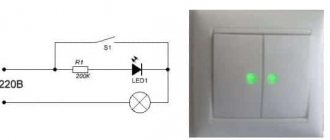
We all know that in most industrial devices it is very important to detect the isolated mains voltage in time. With the help of insulation, here it is necessary to prevent the flow of current (direct or alternating) from the first half of the structure to the other, and also to ensure the transmission of signal and power.
Thanks to insulation, you can isolate potential differences, make the device resistant to interference and protect it from strong voltage surges. Typically, DC or AC optocouplers are needed to detect voltage. They need to be installed on the path where the signal passes.
Under no circumstances should you touch the board when the device is already turned on. This results in electric shocks.
How to build an AC power detector
The PC817B optocoupler contains an infrared light diode that is coupled optically to a photographic transistor. That, in turn, is placed in a dip package with 4 contacts. The standard insulation voltage at input-output is 5 kV, at collector-emitter - up to 80 V, CTR can be up to 600% at an input current of 5 mA.
The circuit does not require an AC transformer. To reduce the voltage, a series capacitor is used, which is connected directly to a network with a voltage of 220 V. A diode is used to rectify the alternating current voltage, and the final voltage at direct current is corrected by the capacitor.
The zener diode is a pre-regulator to completely protect the circuit. If there is a break on the capacitor, for example, if a resistor accidentally burns out, the capacitor voltage does not exceed 5 V. Therefore, the filter capacitor cannot explode.
The resulting input causes a low output signal during a suitable interface with an external structure where there is a pull-up resistor. If the power is turned off, a high-level output signal appears.
It is possible to create an improved version of such a network detector, which will be adjusted to digital technology. It is clear that the most basic and safe way to determine electricity in the network is using a microcontroller. You can't do without an optocoupler here. To safely connect PC817 such a high voltage (220 V) to an optocoupler, a current limit is needed. Due to its magnitude, the resistor power rating must be taken into account.
For a smooth, stable output of a constant current, for example, if we are talking about a GPIO microcontroller, a slight modification of the circuit is needed. The capacitance of the capacitor does not matter much here. It can range from 2 to 10 µF.
Application of 2-directional optocoupler
There is another current option - the use of a 2-directional optocoupler. In another way it is called an AC optocoupler. It includes a pair of internal light diodes. They are directed in the opposite direction. One such model is H11AA1.
Thanks to the design of the conceived universal detector, monitoring a high-voltage signal becomes easier. It helps to ensure the formation of a digital output signal with electroplating. There are no expensive elements in the scheme. It can be assembled within an hour.
The project includes 2 important fragments. One of them processes the high-voltage input, the second isolates the low-voltage section from the high-voltage one. And to enhance circuit protection, you cannot do without a fuse and a metal oxide varistor.
The variator is based on metal oxide. It is a resistor that depends on voltage. It is unique and protects circuits from excess voltage. Thanks to him, fluctuations in this indicator are reduced.
Under normal conditions, the varistor has a high resistance, but when the connected voltage increases, compared to the limit of the variator, it immediately decreases. A varistor can be easily connected between phase and zero, but only after the fuse. Then, if the varistor short circuits, the device will be disconnected from the network due to the fuse.
It is possible to use a pull-up resistor for microcontrollers that do not have this element inside. Moreover, using a two-pin jumper, the correction capacitor is turned on or off, if necessary.
The final unsmoothed output signal is not perfectly smooth, but its fluctuations are no more than 500 mV. The input to this optocoupler is connected to the mains voltage, which is processed by a potential capacitance divider circuit. The highest possible switching voltage of the optocoupler is 30 V, and the transistor that is connected to the output of the optocoupler can withstand a current of up to 10 mA.
One example of using a sensor is when it is a reset circuit at the moment it is connected to the network. The second option is an emergency current system, a microcontroller alarm, or a power failure/resume identifier circuit.
Structure and characteristics
Optocouplers use photodetectors that are sensitive in the near-infrared and visible regions, since this part of the spectrum is characterized by sources of intense radiation that can operate as photodetectors without cooling. Photodetectors with p-n junctions (diodes and transistors) based on silicon are universal, the region of their maximum spectral sensitivity is near 0.8 microns.
Characteristics of optocouplers (optocouplers) with input and output parameters.
The optocoupler is characterized primarily by the current transfer coefficient CTR, that is, the ratio of the input and output signal currents. The next parameter is the signal transmission speed, essentially the cutoff frequency fc of the optocoupler, associated with the rise times tr and cutoff times tf for the transmitted pulses. Finally, the parameters characterizing the optocoupler from the point of view of galvanic isolation: isolation resistance Riso, maximum voltage Viso and pass capacitance Cf.
The input device included in the structure of the optocoupler is designed to create optimal operating conditions for the emitter (LED), to shift the operating point to the linear zone of the current-voltage characteristic. The input device has sufficient speed and a wide range of input currents, ensuring reliable information transmission even at low (threshold) current. The optical medium is located inside the housing, through which light is transmitted from the emitter to the photodetector.
In optocouplers with a controlled optical channel, there is an additional control device through which it is possible to influence the properties of the optical medium using electrical or magnetic means. On the photodetector side, the signal is restored, quickly converting from optical to electrical. The output device on the photodetector side (for example, a phototransistor included in the circuit) is designed to convert the signal into a standard electrical form, convenient for further processing in the blocks following the optocoupler. An optocoupler often does not contain input and output devices, so it requires external circuits to create normal operation in the circuit of a particular device.
Optocoupler connection.
Types and varieties
Optoelectronic devices operate differently depending on which of the two types of directions they belong to:
- Electro-optical.
The operation of the device is based on the principle according to which light energy is converted into electrical energy. Moreover, the transition is carried out through a solid body and the internal photoelectric effect processes occurring in it (expressed in the emission of electrons by the substance under the influence of photons) and the glow effect under the influence of an electric field.
- Optical.
The device operates through the subtle interaction of solids and electromagnetic radiation, as well as using laser, holographic and photochemical devices.
Photonic electronic computers are assembled using one of two categories of optical elements:
- Optocouplers;
- Quantum optical elements.
They are models of devices of the electron-optical and optical directions, respectively.
Optocouplers.
Whether the optocoupler will transmit the signal linearly is determined by the characteristics of the photodetector built into the design. The greatest transmission linearity can be expected from resistor optocouplers. As a result, the process of operating such devices is most convenient. A step lower are models with photodiodes and single bipolar transistors. To ensure the operation of pulsed devices, optocouplers based on bipolar or field-effect transistors are used, since there is no need for linear signal transmission. Finally, photothyristor optocouplers are mounted to ensure galvanic isolation and safe operation of the device.
Interesting on the topic: How to check a zener diode.
Application
There are many areas in which the use of optocouplers is necessary. This breadth of application is due to the fact that they are elements that have many different properties and each of their qualities has a separate area of application.
- Fixation of mechanical impact (devices equipped with an open-type optical channel are used, which can be blocked (exert a mechanical impact), which means the device itself can be used as a sensor): Presence detectors (detection of the presence/absence of paper sheets in the printer);
- End (start) point detectors;
- Counters;
- Discrete speedometers.
- Optocoupler (in most cases used as an information transmitter);
It will be interesting➡ How a Schottky barrier diode works
The use of transistor or integrated optocouplers is especially important if it is necessary to provide galvanic isolation in a signal circuit or a circuit with low control current. The role of a control element can be performed by three-electrode semiconductor devices, circuits that control discrete signals, as well as circuits with special specialization.
Optocoupler.