A photoresistor is a semiconductor radio element that changes its resistance depending on the lighting.
For visible light (sunlight or light from lamps), cadmium sulfide or selenide is used. There are also photoresistors that detect infrared radiation. They are made from germanium with some admixtures of other substances.
The property of changing its resistance under the influence of light is very widely used in electronics.
Appearance and designation on the photoresistor circuit
- Basically photoresistors look like this
- On diagrams they can be indicated as follows:
- or so
Term
A photoresistor is essentially a semiconductor device that, under the influence of light, is capable of changing its conductivity or resistance.
They are distinguished by the absence of a pn junction, which is freely used in solar photographic plates.
And since there is no pn junction, then such an element has the property of passing current regardless of its direction. This distinctive feature makes it possible to use them in AC or DC electrical circuits.
Device
The shape of the case or the active layer changes from model to model, but one thing remains unchanged.
This is the base - a substrate made of ceramic material.
A thin layer of conductor made of gold or platinum is applied on the substrate in a snake-like manner by sputtering.
Various types of photoresist materials can also be used as semiconductors.
If you need to capture visible light with a long wavelength:
The most commonly used are cadmium selenide and cadmium sulfide.
To capture infrared radiation, plates can be made from:
- germanium in pure form or with the addition of small impurities;
- silicon;
- lead sulfide and other chemical combinations based on it.
In pure form, germanium or silicon is found in parts that have an internal photoelectric effect.
Other impurities can be used in devices with an external photoelectric effect.
The production of the first serial bismuth sulphide photoresistors in our country was established in 1948.
Later they were replaced by sulfur-cadmium and selenium-cadmium models, which showed much better parameters.
In any case, the properties remain the same.
The layers deposited in this way have leads to electrodes through which electric current flows.
From above, the entire structure is placed in a housing protected by a thin layer of transparent plastic, through which light fluxes enter.
The shape, size and material of the protective housing may vary. These parameters are determined by the manufacturer based on the purpose of the photoresistor and look different.
The design of a conventional photoresistor can be of different designs:
- in a metal case;
- in a plastic case;
- open type.
Metal spraying is not always used. The conductive layer can be cut from a thin semiconductor layer.
There are also options for film photo sensors.
Designation on diagrams
A photoresistor on a circuit diagram is designated almost the same as a standard resistor. But there is a slight difference. This is still the same rectangle, but in a circle, outside of which there is an image of two arrows at an angle of 45°. These arrows symbolically show the radiation flux incident on the element.
This designation was adopted by the international electrotechnical commission IEC (International Electrotechnical Commission).
In foreign sources you can see another symbol. The photocell is conventionally shown as a broken line. This is an outdated symbol, but it can also be found on diagrams quite often.
Principle of operation
Let's figure out how a photoresistor works?
When it is inactive it is essentially a dielectric. In order for a device to begin conducting current, an external influence must be exerted on it. Thermal or, as in our case, light.
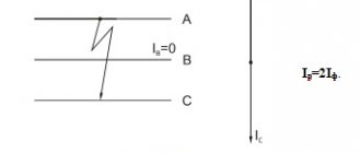
Photons of light hitting the active layer saturate it with electrons, and now the ability to transmit electric current appears. A direct relationship arises that can be displayed on a graph.
The graph clearly shows that the more electrons are formed, the lower the electrical resistance of the semiconductor. The principle of its operation is based on this property of the photoresistor.
Moreover, the effect of electron formation can cause both the visible spectrum of radiation and the infrared. In the latter version, they are capable of creating significantly greater energy.
The susceptibility of the photoresist layer can be increased by doping it with various additives. After such treatment, photoresistance decreases, but photosensitivity in the visible light spectrum increases.
These elements are characterized by the aging process. It is expressed:
- in reducing ohmic resistance;
- photocurrent changes;
- sensitivity increases.
This process does not last long - up to several hundred hours, and then the parameters become stable.
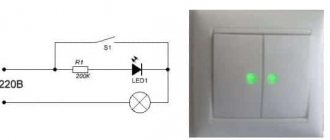
How does a photoresistor work?
In complete darkness, the resistance of these radio components is enormous, can reach tens of megohms, but as soon as the element is exposed to light, its resistance drops sharply to fractions of an ohm.
Photoresistors (PRs) have high sensitivity in a fairly wide range (from infrared to x-ray spectrum), which depends on the wavelength of the light flux. These radio components are still used in many electronic devices due to their high stability over time, small size and rich resistance ratings.
They are usually made in a plastic case with a transparent window and two external terminals; the polarity of the connection does not matter. A photoresistor is a sensor (converter), the electrical resistance of which varies depending on the intensity of the light flux entering it. The stronger it is, the more free charge carriers (electrons) are generated and the lower the resistance of the photoresistor.
The two external metal leads of this sensor go through the ceramic base material to a special photosensitive film, which, by its material properties and its geometry, sets the electrical properties of the resistance of the photoresistor. Since the photosensitive substance by its nature has a fairly high internal resistance, then between both terminals with a thin trace, at an average light intensity, a low total resistance of the photoresistor is obtained. Similar to the human eye, a photoresistor is sensitive to a specific range of wavelengths of light. When choosing a sensor, you have to pay close attention to this, because otherwise it may not react to the light source at all.
For photoresistors, the temperature range is also set as a mandatory parameter. If you use the converter at different temperatures, then it is necessary to add clarifying transformations, because The resistance property of this photocell depends on the temperature. To characterize light intensity, a special value called illuminance (E) is used. It shows the amount of luminous flux that will reach a certain surface. To measure the unit in the SI system, the physical lux (lx) is used, where one lux means that a flux of light of one lumen (lm) is uniformly incident on a surface measuring one meter squared. In real conditions, the luminous flux almost never falls evenly on the surface, so the illumination is slightly higher on average.
Interesting read: operating principle and main characteristics of varistors.
In essence, this is an ordinary transistor, but without a lid in the literal sense. Of course, there is a cover covering the crystal of the device, but it is made of transparent material and visible light can fall on the crystal. By applying some voltage to the base, you can control the resistance of the emitter-collector junction. But it turns out that the junction resistance can also be controlled by ordinary light.
A phototransistor is an ordinary transistor that has one more, additional “base” - a light one. We illuminate - we open the transistor. In such a connection, the base output of the phototransistor can not be used at all - its role is played by light.
Kinds
In general, all photo sensors are divided into two main groups:
- Parts with an internal photoelectric effect.
- Details with external photo effect.
They are distinguished from each other by production technology, or, to be more precise, by the very composition of the photoresist layer.
If in the first case the purest chemical components are used during production, without foreign impurities. Thus, the characteristics of the sensor change; the photoresistor practically does not react to visible light, but works well in the infrared range.
The latter, on the contrary, contain impurities in the semiconductor substance. Due to this, the sensitivity spectrum in the visible light zone expands and even covers the infrared range (heat rays).
Although the operating principle and how to connect these two types are no different - the internal resistance decreases with increasing intensity of the light flux incident on them.
Actually, this property helps when installing boards with photosensors. The question of how to check a photoresistor is solved by checking its resistance with a multimeter. The working element should have greater resistance in the absence of lighting. If light is applied to its sensitive element, the resistance will instantly drop to several kOhms.
Sensitivity and inertia of the photoresistor
The sensitivity of a photoresistor depends on the wavelength of light. If the wavelength lies outside the operating range, then the light has no effect on the phase distribution. We can say that the photoresistor is not sensitive in this wavelength range. These radio components have lower sensitivity than phototransistors and photodiodes.
Another important characteristic of a photoresistor is called inertia; its physical meaning is that there is a certain inertia (or, more simply, a delay time) between changes in illumination and the subsequent change in resistance. It takes about 10 ms for the resistance to drop to its minimum possible value in full light, and about one second for the resistance to rise to its maximum after darkening the same component.
Sensitivity and inertia of the photoresistor.
Application area
In the modern world, the scope of application of these radio components has been significantly expanded.
The use of various photoresistors operating in the visible spectrum is quite extensive. It can be:
- Automatic light switch systems.
- Counting devices.
- Web or paper break sensors.
- Intrusion sensors.
- In devices equipped with exposure meters. For example, such elements could be used in standard point-and-shoot cameras.
In themselves, they are only an element of complex photodetector devices, which, in addition to the photodetector, may include:
- integrated amplifier;
- a microcircuit responsible for automatic lighting adjustment;
- power circuit diagrams, supplemented by a cooling system based on Peltier elements.
All this variety of elements for photodetectors is contained in a small sealed housing.
If these devices operate in the IR range, their scope is slightly different. They are used as part of complex devices such as:
- flame detection sensors;
- non-contact temperature measurement systems;
- humidity level monitoring systems;
- used to detect carbon dioxide;
- in infrared gas analyzers;
- used in paper tape break sensors in printing houses or in the paper industry;
- in industrial electronics, connecting a photoresistor can be used to automatically count products that move along a conveyor belt.
Accordingly, based on the fact that such a resistor will be controlled, its parameters are calculated.
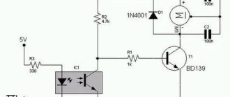
For an example of how this element is used in practice, let's look at the photo relay circuit that controls street lighting.
Automation of street lighting
Automatic devices that turn on street lighting are able to detect the presence/absence of sunlight.
Here is a typical implementation diagram for connecting a photoresistor to automatically activate a night lighting device.
In general terms, the principle of operation of the circuit.
With the onset of twilight and at night, the resistance of the LDR increases, which causes a decrease in the voltage across the variable resistor R2. Transistor VT1 is closed, and VT2 opens, thus supplying voltage to the relay that turns on the lamp.
This is a completely working photo relay circuit, but its main drawback is the lack of hysteresis. This causes the relay to briefly buzz during twilight hours when there are slight changes in illumination.
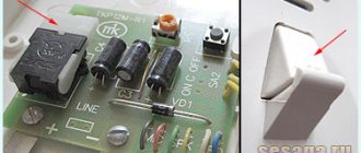
This electronic part helps monitor the ambient light level.
Sensors for other conditions
In the printing industry, designs using a special photoresistor monitor the breakage of a paper roll. They can also be used to count paper sheets on a conveyor belt.
Connecting a photoresistor to Arduino
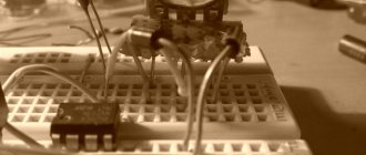
Light sensors that can use photoresistors can be implemented with your own hands based on Arduino boards.
Such schemes are quite simple, there is no question of “where to get them”, since they are available in online stores, and their price does not scare away customers.
A homemade module makes it possible to control the light level and react to its changes.
Having such an Arduino board in hand, it is easy to implement projects such as:
- light sensor;
- to turn on/off the relay;
- starts engines and so on.
Here is a typical example of using a light detector based on an Arduino board.
Food for thought
Firstly, in order not to assemble the circuit on a breadboard, you can use a ready-made module with a photoresistor and a voltage divider on board.
This module is convenient if you need to create a prototype of a device or a mini-school project that should not fail from any touch to the wires.
Second, to measure illuminance in lux, lighting engineers use more sophisticated sensors called lux meters. The task of such a sensor is to sense light, just like the human eye. The light meter module also easily connects to Arduino, but more on that in another lesson.
Advantages and disadvantages
These elements have a significant drawback - the cutoff frequency. It sets the maximum frequency of the sinusoidal signal that regulates the luminous flux.
As a result, the sensitivity of the device is significantly reduced. Accordingly, the performance of devices also decreases, where it takes about ten microseconds to respond - 10^(−5) s.
Some inertia of sensors based on photoresistors also appears. There is a delay in the signal, and this negatively affects the performance of the devices.
But there are also positive aspects.
At a low sensitivity threshold, the photoresistor is inexpensive and its connection is justified by high reliability. Often, it is even useful that the photocell is triggered not instantly, but incrementally, gradually. This feature makes it possible to use these parts in analog-type devices - various sensors and light meters.
Switching
Now you can easily understand the code from the example File | Examples | 05.Control | switchCase
.
Empirically, it turns out that the photoresistor readings range from 0 to 600 (you may have other values, then change them). We divide the interval into four parts using map()
: dark, hazy, medium, bright.
Using the switch
, we select the desired value and display a message.
The scheme remains the same. const int sensorMin = 0; // minimum sensor value const int sensorMax = 600; // maximum sensor value void setup() { Serial.begin(9600); } void loop() { // get data from the sensor int sensorReading = analogRead(A0); // divide the data into four intervals int range = map(sensorReading, sensorMin, sensorMax, 0, 3); // compare the values and display the desired message switch (range) { case 0: // close the sensor with your hand Serial.println("dark"); break; case 1: // throw in some light Serial.println("dim"); break; case 2: // even more light Serial.println("medium"); break; case 3: // sensor under the lamp Serial.println("bright"); break; } delay(1); // pause for stability }