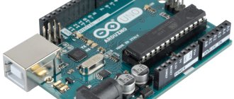
Arduino is an open-source development platform designed for engineers and budding electronics enthusiasts to easily develop a variety of electronics projects. It consists of a physically programmable board (based on the AVR family of microcontrollers) and specialized software or an integrated development environment that can be run on your personal computer to develop programs and load them into the microcontroller.
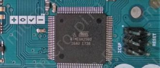
The Arduino uses a boot loader that allows new program code to be written into it. In this article we will look at the issue of writing a system bootloader into the ATmega328 microcontroller (AVR family) and construct a home Arduino system on a printed circuit board based on it. The choice of the ATmega328 IC microcontroller is due to the fact that it is used in the Arduino UNO platform.
About the board
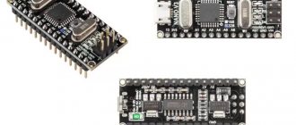
Arduino Nano is an analogue of Arduino Uno, which also runs on the ATmega328P chip, but differs in the board form factor, which is 2-2.5 times smaller than Uno (53 x 69 mm). The dimensions are similar to a pack of cigarettes, and make it easy to assemble complex circuits using wall-mounted installations, but after the stage of creating a layout comes the assembly of working copies, and Nano is better suited for this.
Arduino Nano size: 19 x 43 mm
Comparison of Arduino Uno and Arduino Nano boards
The difference between such a miniature board is that it does not have a remote socket for external power, but instead you can easily connect directly to the pins. The board uses the FTDI FT232RL chip for USB-Serial conversion and uses a mini-USB cable for communication with Arduino instead of the standard one. Communication with various devices is provided by UART, I2C and SPI interfaces.
Otherwise, the interaction methods and characteristics of the chips coincide with the basic Uno model, which is more suitable for experiments than for real projects. There is no more pressing problem for an electronics lover than the desire to design his device beautifully and compactly.
The platform has contacts in the form of pins, so it is easy to install on a breadboard. Arduino Nano is used where compactness is important, and the capabilities of the Mini are either not enough or you don’t want to do soldering.
Buy a development board
We have traditionally made a selection of the most popular boards that can be bought in online stores and provided links to the most reliable suppliers on Aliexpress.
| 3 in one kit: MB102 development board with 3.3V/5V power supply and 65 wire sets | Development board MB102 Breadboard 830 pins | Set of 6 Mini Breadboards 170 Pins Mini Breadboard kit for Arduino |
| Development board 4 in one - 700 connectors from the famous WAVGAT brand | Standard development board 8.5CM x 5.5CM 400 headers | Starter Kit – a set of a breadboard, Arduino and wires |
Characteristics of Arduino Nano
Microcontroller Atmel ATmega168 or ATmega328
| Operating voltage (logic level) | 5 V |
| Input Voltage (Recommended) | 7-12 V |
| Input voltage (limit) | 6-20 V |
| Digital Inputs/Outputs | 14 (6 of which can be used as PWM outputs) |
| Analog inputs | 8 |
| DC current via input/output | 40 mAh from one pin and 500 mAh from all pins |
| Flash memory | 16 KB (ATmega168) or 32 KB (ATmega328) with 2 KB used for the bootloader |
| RAM | 1 KB (ATmega168) or 2 KB (ATmega328) |
| EEPROM | 512 bytes (ATmega168) or 1 KB (ATmega328) |
| Clock frequency | 16 MHz |
| Dimensions | 1.85 cm x 4.2 cm |
First of all, when talking about the characteristics, it should be noted that Nano is available in various versions and the most common are:
- Nano v.2;
- Nano v.3.
The main difference is in the microcontroller itself. The younger version uses Atmega168, Atmega328. The main differences between the chips are the amount of Flash memory:
- mega 328: Flash memory – 32 kb, EPROM – 1024 and RAM – 2 kb;
- mega 168: Flash memory – 16 kB, EPROM – 512 and RAM – 1 kB.
EPROM is a reprogrammable memory device.
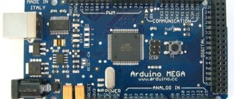
The Arduino Nano's main competitor in size is the Arduino Micro. In general, they are similar, but the “micro” SPI interface is routed to different pins, like the I2C bus, and the number of interrupt pins has also been changed. In general, the boards are similar in size, but the aspect ratios are different, as well as some circuit nuances.
It will be interesting➡ What is arduino nano: features and scope
Arduino Nano has 8 analog inputs, they can be used as a digital output, 14 digital ones, 6 of which can work as a pulse width modulator (PWM), two more are used for I2C and 3 for SPI.
At the opposite end of the board from the micro-USB connector there is an Arudino ICSP header for flashing the microcontroller firmware.
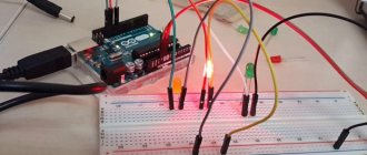
PWM outputs and transistors will help you: regulate engine speed, LED brightness, heater power and much more. And analog inputs will allow you to read values from analog sensors, such as:
- photoresistors;
- thermistors;
- thermocouples;
- humidity meters;
- pressure sensors and others.
Outputs Digital 2 and 3 can be used for external interrupts. These are signals that inform the microcontroller about some important event. Based on these signals, the interrupt routine is called and the necessary actions are performed, for example, exiting the power saving mode and performing calculations.
Based on the Nano board, you will get an excellent miniature Arduino ISP programmer for flashing a number of controllers.
Main characteristics
The Arduino Uno board version R3 has the following characteristics:
- Maximum output current of a 5V pin: 0.8 A.
- Quartz processor clock frequency: 16 MHz.
- Number of analog and digital I/O ports: 20.
- Number of ports supporting pulse width modulation: 6.
- Analog-to-digital converter capacity: 10 bits.
- Maximum permissible current from I/O pin: 0.04 A.
- Microcontroller RAM: 2 KB.
- Flash memory: 32 KB (0.5 KB of which is reserved for bootloader).
- Dimensions of the device: 6.9×5.3 cm.
- Allowable input voltage at the power connector: 7-12 V.
- Electrically Erasable Programmable ROM EEPROM: 1 kB.
- Number of built-in LEDs: 1 (located on port 13).
Additional modifications are being developed for the board to improve its technical characteristics. The latest update package was released on March 15, 2022.
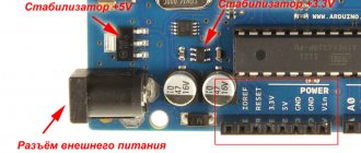
Module power supply
Arduino Nano can work from different power sources, it can be connected either through a Mini-B USB computer, or from a regular unregulated 6-20 volts (pin 30), or regulated 5 volts (pin 27). The board will automatically select the highest voltage supply.
- Via mini-USB or microUSB when connected to a computer;
- Through an external power source, voltage 6-20V.
External power is stabilized thanks to LM1117IMPX-5.0 with a voltage of 5V. When connecting via USB, a Schottky diode is used.
Arduino pins
Arduino Uno pins are divided into 4 groups:
- Power Pins (Vin and GND) are non-programmable ports that produce a stabilized voltage of 5V or 3.3V.
- PWM Pins - ports that support pulse width modulation. The user can change their operating mode using the pinMode function. This type includes pins numbered 2, 5, 6, 9, 10, 11.
- Analog in - analog ports that receive incoming signals from sensors. If there is a lack of general purpose ports, they can be used as digital pins. This group includes contacts A0, A1, A2, A3, A4, A5.
- Digital in - digital ports used to receive 2 types of signals: LOW and HIGH. These include contacts numbered 2-13. Pins #2 and #3 support hardware interrupts.
There are 2 additional contacts on the board: AREF or RESET. The AREF port provides analog input reference voltages for the on-chip ADC. The RESET pin sends low-level signals, causing a hardware reset of the microcontroller.
Description of pins and pinout of Arduino Nano board
The figure shows the numbers and pin assignments of the Arduino Nano (view from the side on which the Atmega328 microcontroller is located):
Each of the Nano's 14 digital pins can be configured as an input or output using the pinMode(), digitalWrite(), and digitalRead() functions. The pins operate at 5 V. Each pin has a 20-50 kOhm load resistor and can carry up to 40 mA. Some pins have special functions:
- Serial bus: 0 (RX) and 1 (TX). The pins are used to receive (RX) and transmit (TX) TTL data. These pins are connected to the corresponding pins of the FTDI USB-to-TTL serial bus chip.
- External Interrupt: 2 and 3. These pins can be configured to trigger an interrupt on either a low value, a rising or falling edge, or a value change. See the attachInterrupt() function for details.
- PWM: 3, 5, 6, 9, 10, and 11. Either pin provides 8-bit PWM using the analogWrite() function.
- SPI: 10 (SS), 11 (MOSI), 12 (MISO), 13 (SCK). These pins provide SPI communication, which, although supported by the hardware, is not included in the Arduino language.
- LED: 13. Built-in LED connected to digital pin 13. If the pin value is high, the LED is lit.
The Nano platform has 8 analog inputs, each with a resolution of 10 bits (i.e., can take 1024 different values). By default, the pins have a measurement range of up to 5 V relative to ground, however it is possible to change the upper limit using the analogReference() function. Some pins have additional functions:
- I2C: A4 (SDA) and A5 (SCL). The pins provide I2C (TWI) communication. The Wire library is used for creation.
It will be interesting➡ The most popular Arduino projects
Additional pair of platform pins:
- AREF. Reference voltage for analog inputs. Used with the analogReference() function.
- Reset. A low signal on the pin resets the microcontroller. Typically used to connect a reset button on an expansion board, which blocks access to the button on the Arduino board itself.
Color interpretation
– gray color – physical pin of the Atmega328 microcontroller;
– light gray color (PD0, PD1, etc.) – microcontroller port number, which is accessible from assembler programs;
– green color (ADC0, etc.) – numbers of analogue pins;
– blue color – pins of UART and SPI ports.
Purpose and pin designations
USB is a USB port designed to connect the Arduino to a computer via a USB cable (a Mini-B USB connector is required).
VIN – power can be supplied here from an external 7-12 V power source (the power supply must be purchased separately). The voltage will be supplied to the stabilizer and dropped to 5 V. Therefore, it is optimal to supply about 9 V to this pin.
5V – through this pin you can also power the board from a 5 volt power source, but the voltage must be more or less stable, since it is supplied directly to the microcontroller (the stabilizer is not involved), and therefore high voltage can kill the main microcontroller.
3.3V – a voltage of 3.3 V will hang on this pin, which is generated from the board’s internal stabilizer. This pin is needed to connect some external devices that require 3.3 V to operate - usually these are all kinds of LCD displays. However, the maximum output current should not exceed 50 mA.
GND – ground (Ground Pin).
AREF – reference voltage for analog inputs. Used as needed (configured using analogReference()).
IOREF – allows you to find out the operating voltage of the microcontroller. Rarely used. It is completely absent on Chinese boards.
Reset – resets the microcontroller, apply a low level to this input.
SDA, SCL – TWI/I2C interface pins.
D0…D13 – digital inputs/outputs. There is a built-in LED hanging on pin D13, which lights up if the HIGH level is applied to pin D13.
0 (RX), 1 (TX) – pins of the UART port (Serial port).
A1…A5 – analog inputs (can also be used as digital).
Appearance of the Arduino Nano board with labeled pins
Here:
RX+TX LEDs - LEDs blink when data is transmitted through the Serial UART serial port (RX and TX pins).
Reset Button – button to restart the microcontroller;
(see other designations above)
FTDI USB chip – FTDI FT323RL chip, which is used to connect the Arduino to a computer via a USB cable. From the Arduino side, this is a serial interface. This interface will be available on the computer as a virtual COM port (drivers for the FTDI chip must be installed - usually included in the Arduino IDE).
It will be interesting➡ What is Arduino: information for beginners
Schematically it looks like this:
Pin number, name, pin type and description:
Main types of development boards for Arduino
Development boards differ in the number of pins located on the panel, the number of buses and configuration. There are boards in which contact connections are made by soldering, but working with them is more difficult than with solderless devices and we will look at them in another article.
Large development board
Colored breadboards
Breadboard with markings
Depending on the characteristics, the most common types are:
- For assembling large chips, solderless boards with 830 or 400 holes are mainly used. For connecting several components and supplying wires to the necessary points - 8, 10, 16 holes;
- With the presence of grooves for adhesion of boards, which allow the implementation of fairly large projects;
- With self-adhesive on the base for secure fastening to the device;
- With symbols printed on the board for connecting devices.
Depending on the cost and manufacturer, the package may also include additional accessories - jumper wires, various connectors. But the main quality criterion always remains the number of contact connectors and their technical characteristics.
Power supply for Arduino Nano
The Arduino Nano can be powered via a Mini-B USB connection, or from an unregulated 6-20V (pin 30) or regulated 5V (pin 27) external power supply. The source with the highest voltage is automatically selected.
The FTDI FT232RL (or CH340G) chip receives power only if the platform itself is powered from USB. Thus, when operating from an external source (not USB), there will be no 3.3 V voltage generated by the FTDI FT232RL (or CH340G) chip, while the RX and TX LEDs blink only when there is a high level signal at pins 0 and 1.
Board diagrams
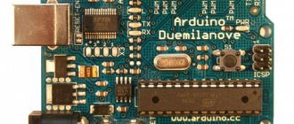
Arduino Uno is an open platform, so users can build it themselves using circuit diagrams. They are freely available on the official website of the Arduino Software company. The diagrams indicate how to connect the device to a PC and the location of all board elements.
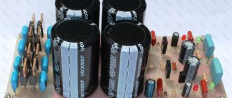
For assembly, you need to purchase an ATmega328 processor, an FT232R microcircuit, a printed circuit board, an LED, SMD resistors and capacitors with a standard size of 0805 and a nominal value of 0.1 μF. Parts are sold in electronics stores or online marketplaces. The average cost of components is 160-220 rubles.
To troubleshoot problems with the Arduino Uno software, you need to flash the board. To re-flash the device, a programmer is required. Methods for connecting Arduino Uno to this device are also indicated on the official electronic circuit diagrams of the board. You can install new software using programs for programming AVR microcontrollers.
You can create electronic board circuits using the Proteus program. The developer is given the opportunity to pre-model the Arduino Uno layout, indicating the location of the main components. Proteus is a paid program.
The free trial version has full functionality, but cannot save a project file.
Installing drivers
On Windows, the drivers will be installed automatically when you connect the board if you used the installer. If you downloaded and extracted the Zip archive or for some reason the board is not recognized correctly, follow the procedure below.
- Click on the Start menu and open Control Panel.
- Go to the System and Security section. Then click "System". Then open Device manager.
- Look under Ports (COM & LPT). You should see an open port named "FT232R USB UART". If the COM and LPT section is missing, look at the Other Devices, Unknown Device section.
- Right-click on the FT232R USB UART port and select the "Update Drivers..." option.
- Then select the option “Browse this computer for driver software.”
- Finally, find the FTDI USB Drivers directory, which is located in the Drivers folder of the Arduino program.
- Windows will then complete the driver installation.
Comparison with other boards
Unlike Arduino Nano, the Arduino Uno board is connected to a PC using a USB cable with a TYPE-B port. Arduino Nano is connected to the computer using a cable with a Mini or Micro USB connector. The Uno board has an additional DC port, which is due to the large dimensions of the device.
The Arduino Mega board has 54 digital and 16 analog ports. This model has more pins that support hardware interrupts. These devices also differ in the amount of internal memory. Arduino Uno is one of the most inexpensive boards. The Arduino Pro Mini platform is cheaper than this device. But it has fewer contacts and additional modules.
Platform haters
In the world of serious programmers and developers, Arduino is not liked very much. Why? Let's look at some popular negative comments about the platform.
- In the Arduino IDE, working with a microcontroller is simplified so much that the Arduino operator does not need to know anything at all about its architecture and how it is generally programmed and configured: everything is done in the form of ready-made and understandable functions. Since when did convenience and simplicity become a bad thing? For a beginner, this is the only way to get acquainted with the world of robotics without studying piles of documentation and receiving the appropriate education. Let me also remind you that Arduino was created primarily for training, and secondly for quickly and conveniently creating prototypes of electronic devices, this is its feature.
- Yes, the standard functions have a lot of protection against fooling a newbie, they are heavy and slow. But a beginner will not need to write such code where speed and memory will be critical! And if necessary, by this time he will already be able to write optimal code and will find quick analogues of Arduino functions on my website or elsewhere on the Internet or write them himself. We also rewrote the standard Arduino core and made it fast and sharp. And one more point: the Arduino core is designed in such a way that it ensures compatibility of code and libraries for all Arduino boards. Have you started making a project on Arduino NANO and are running out of memory/legs? We transfer the project to Arduino MEGA and continue working. Was NANO too big for the project? We transfer it to ATTiny85 without even opening the documentation: most of the libraries work on all Arduino-compatible boards, this is a very big plus, although at the expense of performance and memory.
- And no one promised you HAL! The capabilities of MK are revealed when using libraries (see list of libraries), fortunately the platform’s community is truly huge. You can also always learn how to work with the datasheet and registers and configure anything and everything manually.
- And he does the right thing! One mistake and you could end up with a blocked stone. If desired, you can flash fuses through the Arduino IDE and configure them for other frequencies, we talk about this in this lesson.
- That's right, for children and housewives. The Arduino board is designed for creating breadboards and prototyping; it can be considered as part of an electronic “constructor” for training. The board has all the necessary wiring, why not use it even as the heart of the project?
- True, but there is a small nuance: Arduino IDE is officially free, after a simple installation (Next, Next, Next, Finish) it is immediately ready to work: just select the board from the list and start writing code. Adult development environments require an adult approach and the barrier to entry for working with them is disproportionately high. In addition to difficult installation and configuration, you will find advanced settings of the microcontroller itself in manual mode, reading documentation and datasheets, an “adult” interface and many nuances in the programming itself and compiler settings. It will take a lot of time to study all this.
- Why? The platform does not limit the developer in any way...
- Why? The Arduino IDE does not limit the developer in any way; you can completely abandon Arduino.h and start coding from scratch using registers and assembly inserts, i.e. absolutely the same as in an adult development environment. Not enough “power”? For some reason, it is enough to create 3D printers and other multi-axis CNC machines, the firmware of which consists of tens of thousands of lines of code.
- Yes Yes Yes. But don’t forget about the entry threshold and size of the community with content, libraries and examples “for beginners,” as well as the complexity of working with STM in general. Watch the videos on this channel and compare what is happening with working with Arduino. As for the capabilities and speed of operation, for most amateur projects Arduino (ATmega328/2560) will be more than enough, especially if you know how to write optimal code.
- Yes, because of simple but understandable standard examples, the audience of Arduinists grew very quickly and literally flooded the Internet with their projects, thereby luring other beginners into this hobby. 99% of educational examples, examples of working with libraries and modules are written simply and terribly not optimally: int variables for everything, the ubiquitous delay, blocking loops and so on, in addition to the godless Arduino functions. People take these examples as a basis and continue to write further. But these people are standing on the threshold of a very big door called robotics. Having crossed this threshold, discarding all crooked examples and learning to competently build the structure of their code, they find themselves in a world of limitless opportunities for creativity and research, a world of endlessly interesting and diverse projects on Arduino. This is why I write these lessons.
What else would I like to say about the negativity from “professionals” - in most cases they are simply jealous: in “their time”, to create even a simple project based on a microcontroller, you had to spend a huge amount of time studying the documentation in English for a specific MK model, all the other hardware and microcircuits in the project, learn to work in an unfriendly development environment, wire and solder the board, buy an expensive programmer, and so on. And nowadays you can buy a board for 150 rubles, plug it into USB, launch a “notepad with a Download button” program and start coding using a huge number of ready-made libraries and examples for almost any hardware on the market, and find the answer to any question in Google . Really, the guys are just burning =)