About the board
Arduino Nano is an analogue of Arduino Uno, which also runs on the ATmega328P chip, but differs in the form factor of the board, which is 2-2.5 times smaller than Uno ( 53 x 69 mm ). The dimensions are similar to a pack of cigarettes, and make it easy to assemble complex circuits using wall-mounted installations, but after the stage of creating a layout comes the assembly of working copies, and Nano is better suited for this.
Arduino Nano size:
19 x 43 mm
Comparison of Arduino Uno and Arduino Nano boards
The difference between this miniature board is the absence of a remote socket for external power, but instead you can easily connect directly to the pins. The board uses the FTDI FT232RL chip for USB-Serial conversion and uses a mini-USB cable for communication with Arduino instead of the standard one. Communication with various devices is provided by UART, I2C and SPI interfaces.
Otherwise, the interaction methods and characteristics of the chips coincide with the basic Uno model, which is more suitable for experiments than for real projects. There is no more pressing problem for an electronics lover than the desire to design his device beautifully and compactly.
The platform has contacts in the form of pins, so it is easy to install on a breadboard. Arduino Nano is used where compactness is important, and the capabilities of the Mini are either not enough or you don’t want to do soldering.
See on topic: Water level indicator using Arduino Nano
To summarize
Now, in essence: sensors, there are a bunch of them, you can measure, well, just everything that is measured at all. Electronics: voltage, current, resistance, AC operation, fields. Microclimate parameters: temperature, humidity, pressure, gas content, wind speed, illumination, whatever. There are also a lot of interesting modules: Bluetooth, cellular communications, GPS, displays of various types and sizes, presence sensors, both IR and microwave, modules for wireless communication of Arduinos and much more.
You can control absolutely any piece of hardware that performs its function simply when power is applied: a light bulb, an LED strip, an electric heater, a motor or any electric drive, an electromagnet, a pusher solenoid, and this is all with any supply voltage. But here you need to understand something: Arduino (more precisely, a microcontroller) is a logical device, that is, in an amicable way, it should only give commands to other devices, or receive them from them. What I mean is that neither light bulbs, nor motors, nor heaters, nor worse, work directly from the Arduino. Maximum - LED. With this understanding, we move on. In order for the Arduino to turn on or off (supply power) to another device, you need an intermediary device, such as a relay or transistor. Arduino controls the relay, and the relay, in turn, turns on any desired load with any supply voltage and all that, we’ll talk about this in more detail separately.
As the essence of everything written above, Arduino’s possibilities for connecting and controlling various pieces of hardware are almost limitless; you can implement any idea, even the craziest one. Sensors measure something, actuators control something, at the same time data is sent somewhere, something is displayed on the display and controlled using buttons. Romance!
In my catalog of links to Arduino components you can find almost all existing sensors, modules and other hardware for Arduino, and almost everyone has a link to an article with an example and a library. Use it!
Characteristics of Arduino Nano
| Microcontroller | Atmel ATmega168 or ATmega328 |
| Operating voltage (logic level) | 5 V |
| Input Voltage (Recommended) | 7-12 V |
| Input voltage (limit) | 6-20 V |
| Digital Inputs/Outputs | 14 (6 of which can be used as PWM outputs) |
| Analog inputs | 8 |
| DC current via input/output | 40 mAh from one pin and 500 mAh from all pins |
| Flash memory | 16 KB (ATmega168) or 32 KB (ATmega328) with 2 KB used for the bootloader |
| RAM | 1 KB (ATmega168) or 2 KB (ATmega328) |
| EEPROM | 512 bytes (ATmega168) or 1 KB (ATmega328) |
| Clock frequency | 16 MHz |
| Dimensions | 1.85 cm x 4.2 cm |
First of all, when talking about the characteristics, it should be noted that Nano is available in various versions and the most common are:
- Nano v.2;
- Nano v.3.
The main difference is in the microcontroller itself. The younger version uses Atmega168, Atmega328. The main differences between the chips are the amount of Flash memory:
- mega 328: Flash memory – 32 kb, EPROM – 1024 and RAM – 2 kb;
- mega 168: Flash memory – 16 kB, EPROM – 512 and RAM – 1 kB.
EPROM is a reprogrammable memory device.
The Arduino Nano's main competitor in size is the Arduino Micro. In general, they are similar, but the “micro” SPI interface is routed to different pins, like the I2C bus, and the number of interrupt pins has also been changed. In general, the boards are similar in size, but the aspect ratios are different, as well as some circuit nuances.
Arduino Nano has 8 analog inputs, they can be used as a digital output, 14 digital ones, 6 of which can work as a pulse width modulator (PWM), two more are used for I2C and 3 for SPI.
At the opposite end of the board from the micro-USB connector there is an Arudino ICSP header for flashing the microcontroller firmware.
PWM outputs and transistors will help you: regulate engine speed, LED brightness, heater power and much more. And analog inputs will allow you to read values from analog sensors, such as:
- photoresistors;
- thermistors;
- thermocouples;
- humidity meters;
- pressure sensors and others.
Outputs Digital 2 and 3 can be used for external interrupts. These are signals that inform the microcontroller about some important event. Based on these signals, the interrupt routine is called and the necessary actions are performed, for example, exiting the power saving mode and performing calculations.
Based on the Nano board, you will get an excellent miniature Arduino ISP programmer for flashing a number of controllers.
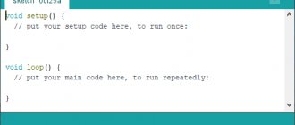
Sketch explanation for the master
The bulk of the code for both the master and slave devices is what I call blink logic code. To flash LED 13 on Arduino we have to do the following:
- Let's add global variables byte i2c_rcv, int time_start, stat_LED and byte value_pot at the top of our sketch
- Initialize the values of global variables inside the setup() function
- Initialize Arduino pin 13 as output pin inside setup() using pinMode()
- Let's add blinking logic code inside the loop() function
Wire Library
To use Arduino's built-in I2C interface we will use the Wire .
This library comes standard with the Arduino IDE. Like other Arduino libraries, the Wire library has ready-made I2C functions to make coding easier for us.
To use the Wire library's features, we must add it to our sketch first. In the sketch above, we have the following line at the top:
#include
After enabling the library, we can use the library's built-in functions.
The first thing to do is connect the device to the I2C bus. The syntax for this is Wire.begin(address). The address is optional for master devices. So, for the Arduino master sketch, we simply add the code Wire.begin(); inside setup().
Now we move on to the loop() loop. Our code will make the Arduino read the value of the potentiometer connected to pin A0 and store it in the value_pot variable.
Sending data
After storing the value from pin A0 into the value_pot variable, we can send the value via I2C. Sending data over I2C includes three functions:
- Wire.beginTransmission()
- Wire.write()
- Wire.endTransmission()
Wire.beginTransmission()
We initiate a send command by first informing the devices on the bus that we will be sending data.
To do this, we call the Wire.beginTransmission(address) function. Address is the I2C address of the slave device that will receive the data. This function does two things:
- It informs the bus that we will send data.
- It informs the intended recipient that the data is ready to be received.
Wire.write()
And then we will send the value of the variable value_to_send using the Wire.write(value) function.
Wire.endTransmission()
After sending the data, we need to free up the network to allow other devices to communicate over the network. This is done using the Wire.endTransmission() function.
Our master device must also receive the potentiometer position from the slave device. We do this using Wire.requestFrom(), Wire.available() and Wire.read().
Wire.requestFrom()
The full syntax for requesting data from a slave is Wire.requestFrom(address, quantity).
Address is the I2C address of the slave device from which we need to receive data, and quantity is the number of bytes we need. For our project, the slave address is 0x08 and we need one byte.
Inside loop() we use Wire.requestFrom(0x08, 1); to request one byte of data from the slave 0x08 .
After issuing the Wire.requestFrom(0x08, 1) command, it must be followed by a read command to obtain a response from the I2C bus.
Write.available()
First we check if there is data on the bus. This is done using the Write.available() function inside an if() conditional statement. The Write.available() function returns the number of bytes waiting to be read.
Wire.read();
To get the available data, we use the Wire.read() function and store the return value in the i2c_rcv variable. Each Wire.read() function call receives only one byte of data from the I2C bus.
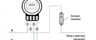
Module power supply
Arduino Nano can work from different power sources, it can be connected either through a Mini-B USB computer, or from a regular unregulated 6-20 volts ( pin 30 ), or regulated 5 volts ( pin 27 ). The board will automatically select the highest voltage supply.
- Via mini-USB or microUSB when connected to a computer;
- Through an external power source, voltage 6-20V.
External power is stabilized thanks to LM1117IMPX-5.0 with a voltage of 5V. When connecting via USB, a Schottky diode is used.
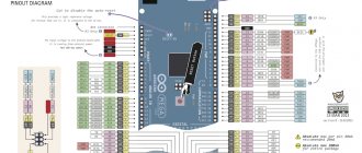
Arduino Nano pinout
The Arduino Nano has a pinout as shown in the picture below:
1 – TX (UART transmission) or D0 port; 2 – RX (UART reception) or port D1; 3.28 – reset (RESET); 4.29 – earth; 5…16 – ports D3…D13; 17 – voltage 3.3 V; 18 – ADC reference voltage; 19…26 – 8 ADC channels A0…A7; 27 – voltage 5.0 V; 30 – plus module power supply 2-20 V
The first two pins are used either for classic serial communication with another device, or as ports for binary data. In arduino nano, the pinout of 5...16 pins, in addition to those indicated, has additional functions:
5 – interrupt INT0; 6 – interrupt INT1 / PWM / AIN0; 7 – timer-counter T0 / I2C SDA bus / AIN1; 8 – timer-counter T1 / I2C SCL bus / PWM; 9,12,13,14 – PWM; 16 – LED.
A more detailed I/O diagram in the figure below (click to enlarge):
Arduino Nano pinout
AIN0 and AIN1 are the inputs of a high-speed analog comparator. In addition, there are 6 channels with pulse width modulator (PWM) output. In addition, there are a larger number of pins to which interrupt requests can be transferred.
The problem with microcontrollers is that despite their great functionality (after all, in addition to the processor, they also have a fairly rich set of peripheral devices), they have a limited number of pins. The designer has something to think about already at the stage of drawing up the circuit diagram, because his goal is to make maximum use of the device, while at the same time avoiding conflicts between the functions of the pins.
Arduino Nano 3.0 pinout
The Arduino Nano 3.0 pinout is no different from the circuit shown above, despite the different controller. ATmega328 differs from ATmega168 in twice the amount of memory of all types:
- flash,
- operational,
- EEPROM
This allows us to improve the firmware and bootloader software, as well as give the user more options for his application task. Arduino nano v 3.0 pinout can be used for programming, but a separate connector is used for these purposes. More on this below.
What is the I2C protocol and how does it work
The term IIC stands for “Inter Integrated Circuits” and is often referred to as I2C or even TWI (2-wire interface protocol), but in all cases the same protocol is hidden behind these designations. I2C is a synchronous communication protocol - this means that both devices that exchange information using this protocol must use a common synchronization signal. Since this protocol uses only 2 lines (wires), a synchronization signal must be transmitted along one of them, and useful information along the other.
The I2C protocol was first proposed by Phillips. The protocol in its simplest case connects 2 devices using 2 lines, one of the devices must be a master and the other a slave. Communication is only possible between master and slave. The advantage of the I2C protocol (interface) is that several slaves can be connected to one master.
The communication diagram using the I2C protocol is shown in the following figure.
Purpose of lines of this interface:
- Serial Clock (SCL) : it transmits the general synchronization signal generated by the master device;
- Serial Data (SDA) : It transfers data between master and slave.
At any time, only the master can initiate the data exchange process. Since this protocol allows multiple slaves, the master must access them using different addresses. That is, only a slave with a given (specified) address must respond to the master’s signal, and all other slaves must “remain silent” at this time. Thus, we can use the same bus (line) to exchange data with several devices.
The voltage levels for transmitted signals in the I2C interface are not strictly defined. In this regard, I2C is quite flexible, that is, if a device is powered by a voltage of 5v, it can use the 5v level to communicate using the I2C protocol, and if the device is powered by a voltage of 3.3v, then it can use the 3v level to communicate using the I2C protocol . But what should you do if, using this protocol, you need to connect devices operating on different supply voltages? In this case, voltage shifters are used.
There are several conditions for data transmission in the I2C protocol. Transmission initialization begins with a drop in the SDA line, which is defined as the 'START' condition in the diagram below. As can be seen from this figure, while the level is falling on the SDA line, at the same time on the SCL line the master maintains the voltage high.
That is, as follows from the figure, a drop in the level on the SDA line is a hardware trigger for the condition for the start of transmission. After this, all devices on this bus switch to listening mode.
Likewise, a rise on the SDA line stops data transfer, which is referred to in the diagram as a 'STOP' condition. At the same time, the master on the SCL line maintains a high voltage level (high).
The following figure shows the structure of the slave address in the I2C protocol.
The R/W bit indicates the direction of transmission of the following bytes; if it is set to HIGH, this means that the slave will transmit, and if it is set to low, this means that the master will transmit.
Each bit is transmitted in its own time cycle, that is, it takes 8 time cycles to transmit a byte of information. After each byte transmitted or received, the 9th time cycle is used to confirm/not acknowledge (ACK/NACK) the receipt of information. This acknowledgment bit (ACK bit) is generated by either the slave or the master, depending on the situation. To confirm the receipt of information (ACK) on the SDA line, the master or slave is set to a low level (low) in the 9th time cycle, otherwise there is no acknowledgment of receipt of information (NACK).
The following figure shows the structure of a transmitted message in the I2C protocol.
Arduino Nano ISCP Circuit
Finally, we must say about connecting the programmer. To program the Atmel controllers on which the Arduino module is assembled, the ICSP interface is used. For Arduino Nano icsp the pinout looks like this (see top of previous picture):
- MISO (master receives from slave);
- +5V (power);
- SCK (clock pulse);
- MOSI (master transmits to slave);
- RESET (reset);
- GND (ground).
The first pin of the 6-pin connector has a square shape at the base and is numbered clockwise when viewed from above. To avoid any doubt regarding the numbering order of the connector pins, below is a fragment of the Arduino board circuit diagram:
This connector connects to a programmer with an SPI (Atmel Serial Programming Interface) interface. In addition, the controller firmware can be changed from the programming environment via a USB cable, so purchasing a programmer becomes optional (it is only needed if there is no bootloader program).
Arduino firmware options
Firmware using Arduino IDE
You can flash the board using the Arduino IDE in a few steps. First of all, you need to download and install the Arduino IDE program itself. You also need to additionally download and install the CH341 driver. The Arduino board needs to be connected to the computer and wait a few minutes until Windows recognizes and remembers it.
After this, you need to download the Arduino IDE program and select the desired board: Tools - Board. You also need to select the port to which it is connected: Tools – Port. The finished firmware can be opened by double-clicking; to download it to the board, you need to click the “Download” button at the top of the toolbar.
In some situations, an error may occur due to the presence of Cyrillic (Russian letters) in the path to the folder with codes. To do this, it is better to create a file with sketches and save it in the root of the disk with an English name.
Firmware using a programmer
One of the easiest ways to flash a board is using a programmer. Filling will be carried out in several stages.
First of all, you need to connect the programmer to the board and to the computer. If the programmer is not recognized by the computer, you need to download and install drivers.
After this, you need to select the board for which you want to flash the bootloader. This is done in the menu Tools >> Payment.
Then you need to select the programmer to which the controller is connected. In this case, USBasp is used.
The last step is to click on “burn bootloader” in the Tools menu.
After this, the download will begin. Completion will occur in approximately 10 seconds.
Arduino firmware via Arduino
In order to flash one board using another, you need to take 2 Arduinos, wires and USB. First of all, you need to configure the board, which will act as a programmer. You need to connect it to your computer, open the Arduino IDE and find a special ArduinoISP sketch in the examples. You need to select this example and flash the board.
Now you can connect the second board that needs to be flashed to the first. After this, you need to go to the Tools menu and set the board to be flashed and the type of programmer there.
You can start flashing the device. As soon as the firmware is opened or written, you need to go to the Sketch menu >> upload through the programmer. The standard download button is not suitable for uploading firmware, since in this case the firmware will be loaded onto the first board that already has the firmware.
Communication Interfaces
Arduino Nano supports I2C interface for communication with various devices and peripherals. One common application is communicating with a display via the I2C bus. Thanks to special technology, you can display sets of characters and data on the display using only 2 pins, in Nano these are pins D4 SDA) and D5 (SCL).
The connection to Arduino Nano is similar - use the previously marked pins. To work with the display you will need a library, which can be downloaded below:
The program code is below:
#include #include LiquidCrystal_I2C lcd(0x27,16,2); // set LCD address to 0x27 for 16 characters and 2 lines void setup() { lcd.init(); // initialize the display // Print a message to the LCD. lcd.backlight(); lcd.print("Hello, world!"); } void loop() { }
Example sketch - controlling the backlight of the I2C LCD1602 module:
#include #include #if defined(ARDUINO) && ARDUINO >= 100 #define printByte(args) write(args); #else #define printByte(args) print(args,BYTE); #endif LiquidCrystal_I2C lcd(0x27,16,2); // set LCD address to 0x27 for 16 characters and 2 lines void setup(){ lcd.init(); // initializing the display lcd.backlight(); lcd.home(); lcd.print("Hello world..."); lcd.setCursor(0, 1); lcd.print("dfrobot.com"); } int backlightState = LOW; long previousMillis = 0; long interval = 1000; void loop(){ unsigned long currentMillis = millis(); if(currentMillis - previousMillis > interval) { previousMillis = currentMillis; if (backlightState == LOW) backlightState = HIGH; else backlightState = LOW; if(backlightState == HIGH) lcd.backlight(); else lcd.noBacklight(); } }
Working with SPI requires two pins for data transfer (master in and out):
- to select the system with which “communication” is taking place (SS or CS – crystal/system select),
- clock signal SCLK.
The official website has a special library for working with it. When writing programs, do not forget to include it with the directive:
#include SPI.h
Now you can organize a communication system.
Features of driver installation
When installing drivers for Arduino Nano on Windows OS, the system will detect the necessary software automatically if the installation file from the official Arduino website was used.
If the drivers were not detected and installed by the system, you must:
- Open the control panel.
- Go to the "System and Security" section.
- Go to the “System” tab.
- Open Device Manager.
- Open a tab with COM and LPT ports.
- If the tab does not have an FT232R USB UART port or a section with COM and LPT connectors, go to the “Other devices” tab and go to the “Unknown device” section.
- Right click on FT232R USB UART.
- Select "Update Drivers".
- Click “Search for drivers on your computer.”
- Select FTDI USB Drivers from the Arduino Drivers folder.
If all steps are completed correctly, the system will complete the installation of the software for AN.