Power source using hydraulics as an example
Let's look at a water tower that has automatic water supply. That is, no matter how much water we consume from the tower, its water level will remain unchanged.
Schematically it will look like this:
A tower with automatic water supply can be considered a power source. In chemical power supplies, a discharge occurs, which leads to the voltage level decreasing during prolonged operation. And what is voltage by analogy with hydraulics? This is the same water level)
Let's cut off the top part of the water tower for clarity. We will get a cylinder that is filled with water. Let's take the ground level as a reference point. Let it be equal to zero.
Now the final question. In which case will the pressure on the bottom be greater? When there is little water in the tower
or when the tower is completely flooded with water so that even the water overflows its edges
Of course, when the tower is only half filled with water , the pressure at the bottom of the tower is less than when the tower is full of water .
I think there is no need to explain that if there is no water in the tower at all, then there will be no pressure at the bottom of the tower.
A battery or accumulator works on the same principle.
On electrical diagrams, its designation looks something like this:
Also, to obtain the required voltage, single-cell power supplies are connected in series. In the diagram it looks like this:
Any battery or DC source has two poles: “plus” and “minus”. The minus is the ground level, as in our example with the water tower, and the plus is the voltage, by analogy with hydraulics this will be the same water level.
About the parallel connection of voltage stabilizers from the point of view of the presence of feedback in them.
As you know, a little more than all modern voltage stabilizers are built as compensatory ones - feedback monitors the voltage at the output of the stabilizer and maintains it constant either by changing the internal resistance between input and output, or by changing the ratio of closed and open states between input and output. This implies the fact that if a voltage exceeding its output is applied to the output of the stabilizer, then the OS will have to turn off the regulatory elements and this stabilizer will come out of the fight for the life of the load. We will not consider here the cases of a linear stabilizer with a push-pull output (used as a power supply for DDR memory terminators) and switching stabilizers with synchronous rectification.
The former should, and the latter, theoretically, can try to reduce the voltage at their output. In the case of using switching stabilizers, you can also consider such hypothetical things as beating conversion frequencies or their self-synchronization... But this is beyond the scope of my current interests. To close the theoretical part, I will add that if someone suggests using external clocking of switching stabilizers with a phase shift, then you are too late. Intel and AMD microprocessors have been powered by multi-phase converters for many years, and if there is a ready-made two- or more-phase controller, then it makes no sense to fence external synchronization for individual stabilizers. Now let's move on to simulating reality.
Series connection of power supplies
Now let's imagine this situation. What will happen if in our trimmed water tower full of water we add another one full of water on top? Schematically it will look something like this:
Do you think the pressure on the ground will decrease or increase? It is clear that it will increase! Yes, and exactly twice as much! Why did it happen? The water level has become higher, therefore, the pressure on the bottom has increased .
A separate article about serial connection.
If the negative of one battery is connected to the positive of another battery, then their total voltage is summed up.
A fully charged battery will look like a tower completely filled with water, given that the automatic water supply pump is running. By analogy, a pump is an emf.
A half-dead battery will look something like this:
We can say that the pump can no longer cope.
A battery set to “zero” will look like this:
The automatic water supply pump has broken down.
Naturally, if you connect a fully charged and half-dead battery in series, their total voltage will look something like this:
Let's demonstrate all this in practice. So we have 2 lithium-ion batteries. I marked them with numbers 1 and 2. I brought out a red wire from the plus of each battery, and a black wire from the minus.
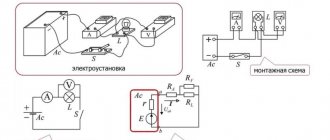
Let's measure the voltage of battery No. 1 using a multimeter. I also wrote how to do this in the article How to measure current and voltage with a multimeter.
On the first battery we have a voltage of 3.66 Volts. This is a typical value for a lithium-ion battery.
In the same way we measure the voltage on battery No. 2
Oh, what a coincidence). The same 3.66 Volts.
In order to connect these batteries in series, we need to do something like this:
Just like in towers, we need to connect the base of one tower to the top of another tower. In power sources, such as batteries or batteries, we need to connect the minus of one battery to the plus of the other. That's what we'll do. We connect the plus of one battery with the minus of the other and we get... the sum of the voltages of each battery! As you remember, on the first battery we had a voltage of 3.66 V, on the second also 3.66 V. 3.66 + 3.6 = 7.32 V.
The multimeter shows 7.33 V. We will attribute 0.01 V to measurement error.
This property works not only with two batteries, but also with an infinite number of them. I don’t think it’s worth saying that if you put 100 of these batteries in a row, connect them in series and touch the outer poles with your bare hands, then all this can even end in death.
Some features of batteries
The classic battery is a car lead-sulfate battery. Available in the form of batteries connected in series to a battery. Its use and charging/discharging are well known. Their dangerous factors are caustic sulfuric acid, which has a concentration of 25-30%, and gases - hydrogen and oxygen - that are released when charging continues after it has chemically ended. The mixture of gases resulting from the dissociation of water is precisely the well-known explosive gas, where there is exactly twice as much hydrogen as oxygen. Such a mixture explodes at any opportunity - a spark, a strong blow.
Batteries for modern equipment - mobile phones, computers - are made in miniature versions, and chargers of different designs are available for charging them. Many of them contain control circuits that allow you to monitor the end of the charging process or charge all elements in a balanced manner, that is, disconnecting from the device those that have already been charged.
Most of these batteries are quite safe, and improper discharging/charging can only damage them (“memory effect”).
This applies to everything except batteries based on the metal Li - lithium. It is better not to experiment with them, but to charge only on specially designed chargers and work with them only according to the instructions.
The reason is that lithium is very reactive. It is the third element of the periodic table after hydrogen, a metal that is more active than sodium.
When working with lithium-ion and other batteries based on it, lithium metal can gradually fall out of the electrolyte and one day cause a short circuit inside the cell. This could cause it to catch fire, leading to disaster. Because it CANNOT be repaid. It burns without oxygen when reacting with water. In this case, a large amount of heat is released, and other substances join the combustion.
There are known cases of fires in mobile phones with lithium-ion batteries.
However, engineering is moving forward, creating more and more new chargeable elements based on lithium: lithium polymer, lithium nanoconductor. Trying to overcome shortcomings. And they are very good as batteries. But... out of harm’s way, it’s better not to do those simple actions with them that are described below.
Parallel connection of power supplies
But what happens if the power supplies are connected in parallel? Let's look at this from the point of view of the same hydraulics. We have the same towers, in which there is water to the very edges:
No, we will not be perverted here. We will simply connect our towers at the very base with a pipe:
Will the pressure at the bottom of each tower change? I think no. It will remain the same as in one of the towers. What has changed? Just the volume of water . It has doubled in size.
But you can say that in the first case we also had 2 times more water!
Yes, this is all true, but what is important here is that the pressure on the bottom of the tower has changed and has also become twice as large. If we make an inset of the same diameter right at the foot of the water tower, then in the case where the water towers stand one on top of the other, the force of the water flow will be twice as fast as if we made exactly the same inset in the picture where we connected the water towers with a pipe. I voiced this idea in more detail in an article about Ohm’s Law.
If we project this whole idea onto our power supplies, it turns out that with a series connection we have the voltage summed up, and with a parallel connection the current strength must be summed up. But this does not mean that the load, which consumed, for example, 1 Ampere, after we connect it to two parallel power sources, will consume 2 Amperes. With a parallel connection, the voltage remains the same, but the battery capacity increases. But the load will still consume the same 1 Ampere, otherwise all this would contradict Ohm’s law.
It's time to look at all this using a real example. So, we have already taken measurements. It remains to connect two power sources in parallel, in our case these are li-ion batteries:
As you can see, the voltage has not changed.
When connecting power supplies in parallel, the condition must be met that they must have the same voltage.
Just think about what could happen if one of the towers is empty?
I think it is not difficult to guess that water from one tower will flow into another tower until their level is equalized (the law of communicating vessels), if the pump of one tower breaks down and it is empty.
It's the same with power supplies. Power supplies of different voltages must not be connected in parallel . This is fraught with the fact that you will kill healthy batteries, and dead ones will remain dead or charge a little. If the difference between the battery voltages is large, then a crazy amount of current can flow in such a circuit, which will cause heating and even fire of the batteries.
Do not connect power supplies of different voltages in parallel
About the parallel connection of voltage stabilizers in the simulator.
The first example is a variation of a simple linear stabilizer from app. note on the 431 type adjustable voltage reference. This was used, for example, in some early ATX power supplies to regulate the voltage at 3.3 V. The drain of the regulation transistor was supplied with 5 V, and the gate resistor was supplied with 12 V.
Since in the simulation we do not care Efficiency, then for simplicity there is only one power source at the input. Also, off the top of my head, I couldn’t find a way to introduce an error into the TL431 reference voltage other than adding a G1 voltage generator to the control electrode circuit. Here is the result of the calculation (menu “DC Analysis”, section “Transient characteristics”):
As you can see, a 3 mV imbalance in the reference voltage is enough for one of the stabilizers to turn into a pumpkin. And this is only 0.12% of the nominal, and not every 431 has an accuracy better than 0.5%. I reject the proposal “let’s put a trimmer in the feedback circuit and adjust the correct division of the load current” on the grounds that typical trimming resistors (Bourns and muRata, cermet, single and multi-turn) have a vibration resistance of up to 1% (change in the fixed voltage ratio or resistance after exposure to vibration with acceleration 20..30 G). I won’t even consider the dances with series resistors at the outputs of stabilizers mentioned in links to foreign resources. Simply because this kills what the voltage stabilizer is actually installed for - constant voltage across the load when its current consumption changes. Then I remembered that there are usually capacitors at the output... Adding 1000 uF capacitors with an ESR of 100 mOhm to the outputs did not make any fundamental differences in the results of simulating the parallel operation of these stabilizers (the “Transient Analysis” menu).
Perhaps someone will say: “The current limit on the first stabilizer will work and the second one will also connect.” But it is obvious that even if this happens, the first one will still continue to work with overload, which will not add reliability to our system. Here is an example of the operation of a pair of LP2951 (maximum load current - 100 mA, current limit in the model - about 160 mA) with a total load current of about 180 mA. Why so old? Because I have them in a convenient DIP for sticking into the “delusional board” and, if any of the readers want to follow the path of Thomas, then I can measure everything IRL.
Simulation results (menu “Transient Analysis”):
As you can see, the second one does not even think about actively participating in saving the load from hunger. And thanks to the higher gain, exiting the game occurs with less imbalance.
That's all. Eat right!
Series-parallel connection of power supplies
Who’s stopping you from connecting batteries or batteries simultaneously in series and in parallel? But is that really possible? Can). Using an example with water towers, it might look like this:
Here we see two towers, each of which consists of two turrets, and these two large towers are connected by a pipe.
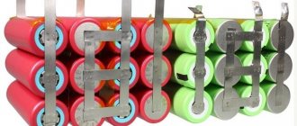
Very often, a series-parallel connection is used in electric vehicles. I recently made a battery for my electric bike from li-ion 18650 batteries. My electric bike required a voltage of 36 Volts. So, now let's turn on the logic. One battery produces 3.6 Volts. To get 36 Volts, I need to connect 10 batteries in series.
To make it easier to understand, I will draw them not according to GOST:
Hooray! I got 36 volts for my electric bike. But the problem is that one such battery can deliver a current of 2800 milliamps to the load for 1 hour or 2.8 amperes for 1 hour. This parameter is indicated on batteries as mAh. I wrote about this in detail in this article “How to measure current and voltage with a multimeter.”
The fact that I connected all the batteries in series does not mean that their capacity has increased 10 times. Only the voltage increased 10 times, since I connected them in series . That is, the total amount turned out to be 36 Volts and the same 2800 mAh as for one battery.
Therefore, in order to increase the capacity, I must connect exactly the same branch of batteries in parallel to this branch, otherwise my electric bike will not travel even a couple of kilometers. I want to ride all day!
No sooner said than done. We connect another branch of 36 Volts. You haven't forgotten the rule that when connected in parallel, the voltage should be the same? As a result we get something like this:
In total, we received the same notorious 36 Volts, but the capacity has doubled. 2800 mAh +2800 mAh = 5600 mAh. Well, with such a battery you can drive a little further. But this also seemed not enough to me, so I added 2 more branches. As a result, my homemade battery for an electric bicycle should schematically look like this:
conclusions
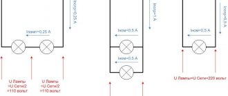
To solve problems, you need to remember the rules for determining the resistance of parallel and series circuits. These rules will be valid not only for two, but also for any number of included elements.
The remaining formulas for voltages and currents can be easily obtained from the formulas for resistances, using Ohm's law for a section of the circuit.
For calculations of branched circuits, Kirchhoff's rules are used.
Rice. 9. All formulas for methods of connecting conductors