Total resistance Rtotal
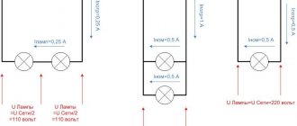
With this connection, a separate current will flow through each resistor. The strength of this current will be inversely proportional to the resistance of the resistor. As a result, the total conductivity of such a section of the electrical circuit increases, and the total resistance, in turn, decreases.
Thus, when connecting resistors with different resistances in parallel, the total resistance will always be less than the value of the smallest individual resistor.
Formula for total conductivity when connecting resistors in parallel:
Formula for equivalent total resistance when connecting resistors in parallel:
For two identical resistors, the total resistance will be equal to half of one individual resistor:
Accordingly, for n identical resistors, the total resistance will be equal to the value of one resistor divided by n.
Serial connection
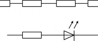
For convenience, when depicting a branched electrical circuit, all resistances are drawn in the form of rectangles, which are resistors. Any such element can have two outputs. One is the beginning and the other is the end. Taking into account the above, we can formulate a definition for a serial connection of conductors: a connection in which the end of the previous element is connected to the beginning of the next one is called serial.
Any conductor has electrical resistance. The purpose of the conversion is to replace the alternating sequence with a single resistor. At the same time, in its electrical properties it should not differ from the entire chain. In simple words, this can be explained as follows: if you take two black boxes that have a pair of terminals each, and one will contain the entire electrical circuit, and the other will be its equivalent, then it will be impossible to determine which of them contains the circuit and which is the equivalent.
When connected in series, the following phenomena occur. Let there be a straight chain containing n resistors: R1 + R2 + … +Rn. Current strength is a quantity that is equal to the charge flowing per unit time. You can imagine that the electric current in the first resistor will be greater than in the second. As a result, a “traffic jam” will occur, and the speed of movement of the charges will slow down.
At the point of connection of the elements, electrons will accumulate, which will lead to an increase in voltage there. Accordingly, the current in the first resistor will decrease, and in the second, on the contrary, it will increase. This will lead to equalization of the number of charges passing through the resistors, so the current strength in almost an instant in the entire series circuit will become the same.
Voltage is the work done to transfer charge. According to the law of conservation of energy, its total value is equal to their sum at various stages. The total potential difference can be determined by adding the voltages across each element. This type of connection is described by the following expressions:
- I = I 1 = I 2 = ... = In;
- U = U1 + U2 + … +Un.
These equalities are fundamental to finding parameters when repeating resistors in a circuit. Using Ohm's law, you can find what the circuit resistance will be. The formula for finding it will look like this: Rpos = R 1 + R 2 +… + Rn.
Case Study
Let's consider an example problem in order to see in practice how you can apply the formulas for series and parallel connection of conductors, which are resistors.
Our input data is as follows:
- Power supply voltage U0 = 120 V;
- R1 = 150 Ohm, R2 = 62.5 Ohm, R3 = 250 Ohm.
We need to find:
Rtot, Itot, I1, I2, I3, U1, U2, U3 and U23.
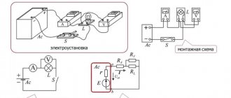
Electrical circuit
First, let's calculate the total resistance R23 of the parallel electrical circuit formed by resistors R2 and R3:
R23 = (R2 * R3) / (R2 + R3) = (62.5 * 250) / (62.5 + 250) = 50 ohms.
Now you can mentally replace the section of parallel-connected resistors R2 and R3 with one common resistance R23, which in turn with R1 will already form an electrical circuit with a series connection of resistors. And we can therefore calculate the total resistance:
Rtot = R1 + R23 = 50 + 150 = 200 Ohm.
Now we can calculate the total current Itot of this series electrical circuit, equal to the simultaneous electric current I1 flowing through resistor R1, using Ohm's law:
Itot = U0 / Rtot = 120 / 200 = 0.6 A = I1.
Now we can calculate the voltage U1 across resistor R1 and the total voltage U23 in a parallel electrical circuit consisting of resistors R2 and R3:
U1 = R1*I1 = 150 * 0.6 = 90 V.
And since U0 = U1 + U23, we get U23 = U0 - U1 = 120 - 90 = 30 V = U2 = U3.
Finally, we calculate I2 and I3:
I2 = U2 / R2 = 30 / 62.5 = 0.48 A
I3 = U3 / R3 = 30 / 250 = 0.12 A.
Browser online calculator
If there are few elements in the circuit, then, by simplifying the circuit, it is quite easy to calculate, using formulas for parallel and series connection of resistors, the total impedance of the circuit. But if there are many elements in the circuit, and it is also such that it contains both connections (combined), it is easier to use online browser calculators.
They are based on the same formulas for calculating the equivalent resistor, but all calculations occur automatically. There are a huge number of offers of such calculators. But at the same time they all work the same. Online calculation is a program code that contains a calculation algorithm. The consumer only needs to indicate in special cells what type of connection is used, how many elements are in the circuit and the resistance of the resistors. Next, you need to click the “Calculate” button and get the answer in a matter of seconds.
It should be noted that, even if this is not indicated in the program, all values are entered only in the International System of Units, current - ampere, voltage - volt, resistance - Ohm. Then the answer will be in Ohms.
A bonus is that many such programs immediately calculate the power of the element. For this, the formula is used: P = U2/Ro = I2*Ro, W.
Resistor element parameters
- For resistors, the concept of power is used. When an electric current passes through them, thermal energy is released and dissipated into the surrounding space. The power of a part is a parameter that shows how much energy it can release in the form of heat while remaining operational. The power depends on the dimensions of the part, so for small foreign resistors it is determined by eye, comparing with Russian ones, the technical characteristics of which are known;
Resistor E24 resistance range
Important! Imported resistor elements of identical power have slightly smaller sizes, since Russian ones are produced with some margin in this indicator.
The diagram shows the power as follows.
Power symbol
- The second parameter is the resistance of the element. On Russian parts of the MLT type and large imported samples, both parameters are indicated on the case (power - W, resistance - Ohm, kOhm, mOhm). To visually determine the resistance of miniature imported elements, a system of symbols using colored stripes is used;
Color coding of resistors
- Tolerances. It is impossible to manufacture a part with a nominal resistance that exactly matches the declared value. Therefore, error limits, called tolerance, are always indicated. Its value is 0.5-20%;
- TCS – temperature coefficient. Shows how the resistance varies with a 1°C change in external temperature. It is desirable, but not necessary, to select elements with close or identical values of this indicator for one circuit.
Types of resistors
The internal structure of the part can be different, but mainly it is a cylindrical insulator, with a layer applied to its outer surface or several turns of thin wire that conduct current and are designed for a given resistance value, measured in ohms.
Existing types of resistors:
- Permanent. They have constant resistance. They are used when a certain section of the electrical circuit requires setting a specified current or voltage level. Such components must be calculated and selected according to parameters;
- Variables. Equipped with several output contacts. Their resistance can be adjusted, which can be smooth or stepwise. An example of use is volume control in audio equipment;
- Tuning – are a variant of variables. The difference is that the trimming resistors are adjusted very rarely;
- There are also resistors with nonlinear characteristics - varistors, thermistors, photoresistors, the resistance of which changes under the influence of lighting, temperature fluctuations, and mechanical pressure.
Important! The material for the manufacture of almost all nonlinear parts, except for carbon varistors used in voltage stabilizers, are semiconductors.
Determination of magnitude
Current is the ordered movement of charge carriers under the influence of an electric field. The ability of a substance to conduct current is called electrical conductivity. The more particle carriers a material has, the more conductive it is . Depending on this characteristic, all substances are divided into three types:
- Conductors. Characterized by good electrical conductivity. These include metals and their alloys, as well as electrolytes.
- Dielectrics. Substances that practically do not conduct electric current. These are mainly gases, rubber, mineral oils, and plastics.
- Semiconductors. Materials that have two types of conductivity simultaneously - hole and electronic. These are substances that have a covalent bond: silicon, germanium, selenium.
The reciprocal of electrical conductivity is called electrical resistance. That is, it is a physical quantity that prevents the passage of current. In addition to the ability of any material to limit the number of charges passing through it, there is a special radio element that limits the current - a resistor .
Thus, there are two concepts of resistance: a radio element and a physical quantity.
Radio element resistance
The term "resistor" comes from the Latin word resisto - "resistance". All resistors are divided into constant and variable. The latter allow you to change your resistance. On diagrams and in literature, such a radio component is signed with the Latin letter R. The unit of measurement is considered to be Ohm. Graphically, the resistor is indicated as a rectangle with two terminals from the middle of the edges. In addition to the nominal resistance, it is characterized by power dissipation and accuracy class.
At its core, it is a passive radio element that converts part of the electrical energy into thermal energy. Thus, it limits the current, linearly converting its strength into voltage and vice versa. The main parameter describing the resistance is found according to Ohm's law for a section of the circuit using the following formula: R = U/I, where:
- R - electrical resistance, Ohm.
- U is the potential difference applied to the element, V.
- I is the current passing through the resistor, A.
But here it should be noted that this law is valid only for resistive circuits. That is, for those in whose calculations capacitance and inductance are neglected. If this formula is applied to reactive elements, then for the inductor the resistance will be zero, and for the capacitor it will be infinite. But this is true for constant current and voltage.
With variable values, the voltage across the inductance will not be zero, as will the current passing through the capacitor. Such cases are no longer described by resistance, since it assumes constant current and voltage values.
Specific parameter of a substance
To distinguish between the concept and the element, the name electrical resistivity was introduced. It is denoted by the Greek symbol ρ. In the International System of Units, this value is measured in Ohms times a meter. It depends solely on the properties of the material.
To calculate the electrical resistance of a homogeneous substance, the formula is used: R = ρ* l/S, where:
- l—conductor length, m;
- S—cross-sectional area, m2.
Therefore, in a physical sense, the resistivity of a material is the reciprocal of the conductivity, which is the resistance of a homogeneous conductor of unit length and cross-sectional area. This means that it is numerically equal to the impedance of a section of an electrical circuit made of a substance one meter long and a cross-sectional area of one square meter.
For each substance, the resistivity is known and is a reference value. For example, for copper - 0.01724 Ohm*mm2/m, aluminum - 0.0262 Ohm*mm2/m, bismuth - 1.2 Ohm*mm2/m, nichrome - 1.05 Ohm*mm2/m. These data were obtained at a temperature of t = 20 °C, since materials have the property of changing their specific characteristics with changes in temperature. Thus, the conductivity of metals increases with decreasing temperature, and that of semiconductors decreases.
Features of calculations
To calculate the complete circuit, the internal resistance ( R int) of the source is taken into account using the formula:
Capacitance
I = E (EMF)/ (Req + Rin).
The existing circuit is transformed in order to simplify it according to the principles discussed above using equivalent resistances. Next, we use the classical relationships of electrical quantities, which are based on Ohm’s law.
Specific technologies are also used:
- loop currents;
- nodal potentials;
- equivalent generator;
- overlays
For your information. In addition to simplifying the circuits, standard methods for converting mathematical formulas are used. In some situations, it is more convenient to operate with fractional quantities, so you should update the relevant knowledge from the school curriculum in your own memory.
Using power and voltage
If, of all the known data, you only have the value of power consumption and voltage, you need to use a simple formula that does not include resistance: P = IU
In this case, from the same formula you can get the following: I = P/U
This formula is suitable for a direct current circuit. And to calculate the current strength in circuits with alternating current (you may need this formula if you want to calculate the current strength in an electric motor), you also need to take into account the power factor (also called “cosine phi”).
In this case, for an electric motor with three phases, it is necessary to construct the calculation a little differently.
Find P, taking into account the efficiency: P1 = P2/η
In this formula, P 2 is the active shaft power and η is the efficiency. These values can usually be found on the engine itself.
After this, you need to find the total power taking into account the power factor (aka cos φ, its value is indicated on the engine): S = P1/cosφ
Next, determine the current consumption: Inom = S/(1.73 U)
1.73 is the root of three, this value is needed to calculate a three-phase circuit. The voltage value will depend on the method of switching on the electric motor (triangle or star) and Volts, most often 380.
Voltage divider circuit using resistors
The voltage divider circuit includes an input voltage source and two resistors. Below you can see several schematic versions of the divider, but they all have the same functionality.
We recommend reading: DIY DC voltage multiplier
Let's denote the resistor that is closer to the plus of the input voltage (Uin) as R1, and the resistor that is closer to the minus as R2. The voltage drop (Uout) across resistor R2 is the reduced voltage resulting from the use of a resistor voltage divider.