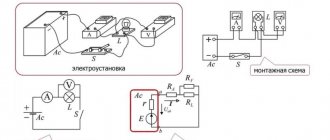
When an alternating sinusoidal voltage is applied to a circuit (Figure 6.2.1) with a resistor and capacitor connected in parallel, the same voltage is applied to both components of the circuit.
The total circuit current I branches into the current in the capacitor IC (the capacitive component of the total current) and the current in the resistor IR (the active component).
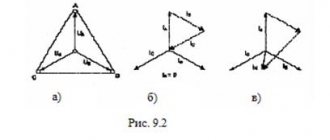
between the currents I, IC and IR due to the capacitive reactance XC of the capacitor. They can be represented using a vector current diagram (Fig. 6.2.2).
In the conductivity triangle , G=1/R , BC=1/XC , and Y represents the so-called total conductance of the circuit in cm, while G is active and BC is reactive (capacitive) conductivity.
Because of the phase shift between current and voltage in circuits like this, simple arithmetic addition of effective or peak currents in parallel branches is not possible. But in vector form: I = IR +IC .
The calculation is carried out using the following formulas resulting from the vector diagram and conductivity triangle:
For a circuit with a resistor and capacitor connected in parallel, measure the rms current in resistor IR and capacitor IC , the total current I , and calculate the phase angle j , circuit impedance Z , and capacitive reactance BC.
· Assemble the circuit according to the diagram (Fig. 6.2.4), connect an adjustable sinusoidal voltage source and set its parameters: U = 5 V, f = 1 kHz.
· Perform measurements of U , I , IC , IR and record the results in the table. 6.2.1. If you make measurements using virtual instruments, then also measure R, j, XC, Z.
| U, B | I, mA | IC, mA | IR, mA | j, deg | R, Ohm | XC, Ohm | Z, Ohm | Note |
| Calculation | ||||||||
| Virt. Change |
Capacitive reactance and circuit resistance
· Compare the calculation results with the results of virtual measurements (if any).
What kind of lighting do you prefer?
Built-in Chandelier
· Construct a vector diagram of currents (Fig. 6.2.5) and a conductivity triangle (Fig. 6.2.6).
Series connection of a resistor and an inductor
When an alternating sinusoidal voltage is applied to a circuit (Fig. 6.3.1) with a resistor and inductor in series, the same sinusoidal current flows in both components of the circuit.
| U, B | I, mA | IC, mA | IR, mA | j, deg | R, Ohm | XC, Ohm | Z, Ohm | Note |
| Calculation | ||||||||
| Virt. Change |
Parallel connection of resistor and capacitor
Knowing the field energy density at each point, one can find the field energy contained in any volume V
. To do this you need to calculate the integral:
Expert opinion
It-Technology, Electrical power and electronics specialist
Ask questions to the “Specialist for modernization of energy generation systems”
Parallel Voltage - Formula, Current, Connection of Capacitors and Resistors For a circuit with a parallel connection of resistor and capacitor, measure the rms current in resistor IR and capacitor IC, the total current I and calculate the phase angle j, circuit impedance Z and capacitive reactance conductivity B C. Ask, I'm in touch!
DEFINITIONS
- characteristic of a conductor, a quantitative measure of its ability to hold an electric charge
- a quantitative characteristic showing the degree of possible participation of a body in electromagnetic interactions
- a device designed to obtain the required values of electrical capacity and capable of accumulating and releasing (redistributing) electrical charges
- potential difference between two points in an electrical circuit; in a section of a circuit that does not contain electromotive force, is equal to the product of the current strength and the resistance of the section
Parallel voltage
It will be interesting➡ How much do ceramic capacitors cost?
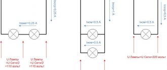
In a parallel connection, a separate current will flow through each capacitor, depending on the capacitance of the capacitor:
Expert opinion
It-Technology, Electrical power and electronics specialist
Ask questions to the “Specialist for modernization of energy generation systems”
15. Connection of capacitors (parallel and series) Due to the fact that the cross-section of real conductors is tens of mm2, Ohm mm2 m is chosen as the unit of resistivity. Ask, I’m in touch!
Capacitor Energy Formula
The voltages on different capacitors will, generally speaking, be different, since charging capacitors of different capacities with the same amount of electricity always requires different voltages.
Types of capacitor connections.
The smaller the capacitance of the capacitor, the greater the voltage required in order to charge this capacitor with the required amount of electricity, and vice versa.
Thus, when charging a group of capacitors connected in series, the voltages on small capacitors will be greater, and on large capacitors - less.
A series connection of capacitors is the connection of two or more capacitors in the form of a circuit in which each individual capacitor is connected to another individual capacitor at only one point. The current (iC) charging a series capacitor circuit will be the same for all capacitors because it has only one possible path.
Alternating current
Gentlemen, one wonderful summer day I took my laptop and left the house to go to my summer cottage. There, sitting in a rocking chair in the shade of apple trees, I decided to write this article. The breeze rustled in the branches of the trees, swaying them from side to side, and in the air there was that very atmosphere conducive to the flow of thoughts, which is so sometimes necessary...
However, enough of the lyrics, it’s time to move directly to the essence of the issue indicated in the title of the article.
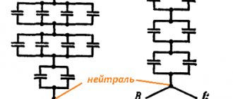
So, parallel connection of capacitors... What is parallel connection anyway? Those who have read my past articles will certainly remember the meaning of this definition. We came across it when we talked about parallel connection of resistors. In the case of capacitors, the definition will have exactly the same form. So, a parallel connection of capacitors is a connection when some ends of all capacitors are connected into one node, and the other ends into another.
Of course, it is better to see once than to hear a hundred times, so in Figure 1 I showed an image of three capacitors that are connected in parallel. Let the capacity of the first be C1, the second – C2, and the third – C3.
Figure 1 – Parallel connection of capacitors
In this article we will look at the laws by which currents, voltages and alternating current resistances change when capacitors are connected in parallel, as well as what the total capacitance of such a design will be. Well, of course, let’s talk about why such a connection might be needed at all.
I suggest starting with tension, because with it everything is extremely clear. Gentlemen, it should be quite obvious that when capacitors are connected in parallel, the voltages across them are equal to each other. That is, the voltage on the first capacitor is exactly the same as on the second and third
Why, exactly, is this so? Yes, very simple! The voltage across a capacitor is calculated as the potential difference between the two legs of the capacitor. And with a parallel connection, the “left” legs of all capacitors converge into one node, and the “right” legs into another. Thus, the “left” legs of all capacitors have one potential, and the “right” legs have another. That is, the potential difference between the “left” and “right” legs will be the same for any capacitor, and this just means that all capacitors have the same voltage. You can see a slightly more rigorous conclusion to this statement in this article. In it we presented it for parallel connection of resistors, but here it will sound absolutely the same.
So, we found out that the voltage on all parallel-connected capacitors is the same. This, by the way, is true for any type of voltage - both direct and alternating. 1.5 V battery to three capacitors connected in parallel . And all of them will have a constant 1.5 V. Or you can connect to them a sinusoidal voltage generator with a frequency of 50 Hz and an amplitude of 310 V. And each capacitor will have a sinusoidal voltage with a frequency of 50 Hz and an amplitude of 310 V. It is important to remember that parallel-connected capacitors will have the same not only amplitude, but also frequency and phase of the voltage.
And if with voltage everything is so simple, then with current the situation is more complicated. When we talk about current through a capacitor, we usually mean alternating current. You remember that direct currents do not flow through capacitors? A capacitor for DC is like an open circuit (there is actually some capacitor leakage resistance, but it is usually neglected because it is so large). Alternating currents flow quite well through capacitors, and can have very, very large amplitudes. It is obvious that these alternating currents are caused by some alternating voltages applied to the capacitors. So, let us still have three parallel-connected capacitors with capacitances C1, C2 and C3. Some alternating voltage with complex amplitude is applied to them. Due to this applied voltage, some alternating currents with complex amplitudes will flow through the capacitors. For clarity, let's draw a picture in which all these quantities will appear. It is presented in Figure 2.
Figure 2 – Looking for currents through capacitors
First of all, you need to understand how the currents are related to the total source current. And they are connected, gentlemen, all according to the same first Kirchhoff law, which we have already become acquainted with in a separate article. Yes, then we looked at it in the context of direct current. But it turns out that Kirchhoff’s first law remains true in the case of alternating current! It’s just that in this case it is necessary to use complex current amplitudes. So, the total current of three capacitors connected in parallel is related to the total current like this
That is, the total current is actually simply divided between the three capacitors, while its total value remains the same. It is important to remember one more important thing - the frequency of the current and its phase will be the same for all three capacitors. I will have exactly the same frequency and phase . Thus, they will differ only in amplitude, which will be different for each capacitor. How to find these same current amplitudes? Very simple! In the article about capacitor resistance, we related the current through the capacitor and the voltage across the capacitor through the resistance of the capacitor. We can easily calculate the resistance of a capacitor, knowing its capacity and the frequency of the current flowing through it (remember that for different frequencies a capacitor has different resistance) using the general formula:
Using this wonderful formula, we can find the resistance of each capacitor:
The complex amplitude of the current is related to the complex amplitude of the voltage according to Ohm’s law for alternating current networks (we talked about this in more detail in the previous article):
Using this formula, we can easily find the current through each of three parallel-connected capacitors:
The total current in the circuit, which flows into node A and then flows out of node B, is obviously equal to
Just in case, let me remind you once again that this happened on the basis of Kirchhoff’s first law. Please note, gentlemen, one important fact - the larger the capacitance of the capacitor, the lower its resistance and the larger part of the current will flow through it.
Let's imagine the total current through three parallel-connected capacitors as the ratio of the voltage applied to them and some equivalent total resistance Zc∑ (which we do not yet know, but which we will later find) of the three parallel-connected capacitors:
Reducing the left and right sides by U, we get
Thus, we get an important conclusion: when connecting capacitors in parallel, the reverse equivalent resistance is equal to the sum of the reverse resistances of the individual capacitors. If you remember, we got exactly the same output when connecting resistors in parallel.
What happens to the capacity? What is the total capacitance of a system of three capacitors connected in parallel? Is it possible to find this somehow? Of course you can! And what's more, we almost did it. Let's substitute the decoding of capacitor resistances into our last formula. Then we will get something like this:
After elementary mathematical transformations, accessible even to a fifth grader, we obtain that
This is our next extremely important conclusion: the total capacitance of a system of several parallel-connected capacitors is equal to the sum of the capacitances of the individual capacitors.
So, we have looked at the main points regarding parallel connection of capacitors. Let's summarize them all in a concise manner:
- The voltage on all three parallel-connected capacitors is the same (in amplitude, phase and frequency);
- The amplitude of the current in a circuit containing parallel-connected capacitors is equal to the sum of the amplitudes of the currents through the individual capacitors. The greater the capacitance of the capacitor, the greater the amplitude of the current through it. The phases and frequencies of the currents on all capacitors are the same;
- When connecting capacitors in parallel, the reverse equivalent resistance is equal to the sum of the reverse resistances of the individual capacitors;
- The total capacitance of parallel-connected capacitors is equal to the sum of the capacitances of all capacitors.
Gentlemen, if you remember and understand these four points, then, one can say, I wrote the article not in vain.
Now, to reinforce the material, let’s try to solve some problem involving parallel connection of capacitors. Because, very likely, if you have not heard anything before about parallel connection of capacitors, then everything written above can be perceived simply as a set of abstract letters that are not very clear how to apply in practice. Therefore, in my opinion, the presence of tasks close to practice is an integral part of the educational process. So, the task.
Let's say we have three parallel-connected capacitors with capacitances C1 = 1 μF , C2 = 4.7 μF and C3 = 22 μF. Umax = 50 V and frequency f = 1 kHz is applied to them . Need to determine
a) voltage on each capacitor;
b) the current through each capacitor and the total current in the circuit;
c) the resistance of each capacitor to alternating current and the total resistance;
d) the total capacity of such a system.
Let's start with tension. We remember that the voltage on all capacitors is the same - that is, sinusoidal with a frequency f = 1 kHz and amplitude Umax = 50 V. Let's assume that it changes according to a sinusoidal law. Then we can write the following
So we have answered the first question of the problem. The voltage oscillogram on our capacitors is shown in Figure 3.
Figure 3 – Voltage oscillogram on capacitors
Next, using general formulas for capacitor resistance, we calculate the resistance of each capacitor to a current with a frequency f = 1 kHz :
Yes, we see that our resistances are not only complex, but also with a minus sign. However, this should not bother you, gentlemen. This only means that the current through the capacitor and the voltage across the capacitor are out of phase with respect to each other, with the current leading the voltage. Yes, the imaginary unit here shows only a phase shift and nothing more. To calculate the current amplitude, we only need the modulus of this complex number. All this has already been discussed in the past two articles (one and two). Perhaps this is not entirely obvious and some kind of visual illustration of this matter is required. This can be done on a trigonometric circle and, hopefully, a little later, I will prepare a separate article dedicated to this, or you can figure out how to show it visually yourself, using data from my article about complex numbers in electrical engineering. Now nothing prevents you from finding the inverse total resistance:
Find the total resistance of our three parallel connected capacitors
It should be remembered that this resistance is only true for a frequency of 1 kHz. For other frequencies the resistance value will obviously be different.
The next step is to calculate the amplitudes of the currents through each capacitor. In the calculation we will use resistance modules (discard the imaginary unit), remembering that the phase shift between current and voltage will be 90 degrees (that is, if our voltage changes according to the sine law, then the current will change according to the cosine law). You can also carry out calculations with complex numbers, using complex amplitudes of current and voltage, but, in my opinion, in this problem it is easier to simply take into account the phase relationships. So, the amplitudes of the currents are equal
The total amplitude of the current in the circuit is obviously equal to
We can afford to add the signal amplitudes like this, because all currents through parallel-connected capacitors have the same frequency and phase. If this requirement is not met, you cannot simply take it and fold it.
Now, remembering the phase relationships, no one is stopping us from writing down the laws of current change through each capacitor
And the total current in the circuit
Oscillograms of currents through capacitors are shown in Figure 4.
Figure 4 – Oscillograms of currents through capacitors
Well, to complete the task, the simplest thing is to find the total capacity of the system as the sum of the capacities:
By the way, this capacitance can be used to calculate the total resistance of three parallel-connected capacitors. As an exercise, the reader is invited to see this for himself.
In conclusion, I would like to clarify one, perhaps the most important question: why is it necessary to connect capacitors in parallel in practice ? What does this give? What opportunities does it open to us? Below, point by point, I outlined the main points:
- Parallel connection of capacitors increases the system capacity. Perhaps this is the most basic and important point. For example, our system requires a capacitance of at least 1000 μF, but we only have 220 μF capacitors at our disposal. What to do? That's right, take about five of these capacitors and get the required capacity.
- Capacitors are often used to smooth out voltage ripples. It happens that in this case very significant pulse currents flow through the capacitor (for example, in switching power supplies). Each capacitor can by no means withstand an infinitely large amount of pulse current. Thus, if the magnitude of the pulse current in the system exceeds the maximum permissible current for a given type of capacitors, then several of them are connected in parallel. In this case, the current is distributed between these capacitors.
- There is such a thing as “capacitor resonance”. We will talk about it in detail later. To be brief, the essence of the phenomenon is that at high frequencies, starting from a certain resonant frequency, due to parasitic inductances, the capacitor ceases to be a capacitor and begins to behave like a choke. This resonant frequency is different for different capacitors: for some it is higher, for others it is lower. So, when filtering a signal in a wide frequency range is needed, parallel connection of capacitors with different resonant frequencies is used. For example, capacitors with a capacity of 0.1 μF, 10 nF, 100 pF, 22 pF are connected in parallel. This connection will provide effective interference suppression over a wide range. We will discuss this interesting phenomenon in more detail another time.
Well, we end here, gentlemen. Thank you for your attention and see you again!
Join our VKontakte group
Questions and suggestions to the admin: This email address is being protected from spambots. You need JavaScript enabled to view it.
Social button for Joomla
Serial connection
Series connection of capacitors is their connection directly one after another without branching the conductor. From the voltage source, charges are supplied to the plates of the first and last capacitors in the chain.
Due to electrostatic induction on the internal plates of adjacent capacitors, charge equalization occurs on the electrically connected plates of adjacent capacitors, so electric charges of equal magnitude and opposite sign appear on them.
With this connection, the electric charges on the plates of individual conductors are equal in magnitude:
Total voltage for the entire circuit:
Obviously, the voltage between the conductors for each capacitor depends on the accumulated charge and capacity, i.e.:
Therefore, the equivalent capacitance of the series circuit is:
It follows that the reciprocal of the total capacitance is equal to the sum of the reciprocals of the individual capacitances:
Mixed compound
A mixed connection of capacitors is a connection in which there is a connection in series and parallel at the same time. To understand in more detail, let's look at this connection using an example:
The figure shows that two capacitors are connected in series at the top and bottom and two in parallel. You can derive the formula from the compounds described above:
The basis of any radio technology is a capacitor; it is used in a wide variety of circuits - these include power supplies and applications for analog data storage signals, as well as in telecommunications for frequency regulation.
Parallel and series connection of capacitors - All about electrics
The behavior and characteristics of radioelements depend on the type of current flowing (direct, alternating) and on the method of their connection.
Expert opinion
It-Technology, Electrical power and electronics specialist
Ask questions to the “Specialist for modernization of energy generation systems”
Formula for calculating a series connection of a capacitor But if there is still at least some logic in the parallel or series connection of capacitors, then who needs a mixed one at all? Ask, I'm in touch!
Topic: Load resistors in parallel with the main capacitors of the power supply unit
Theme Options
In some circuits of factory UMZCHs I have more than once encountered high-resistance resistors standing parallel to the main power supply banks. The question is, does it make sense? Or is it just an extra heater in the amplifier. And if so, what rating is needed for a conventional +-55V transformer power supply, with capacitances of 30,000 microfarads per arm.
pyos
, got it, thanks for the answer! Only 0.25 is probably not serious like that) I’m not greedy, can I plug in two-watt ones? )
What for? No, if you have a couple of extra two-watt units, then for God’s sake. The permissible denomination in this case can be reduced accordingly.
this is done for two reasons. The first is to ensure that the charge on the banks is discharged after switching off, so that it doesn’t get screwed up during repairs. Konstantin Musatov wrote about the second reason, but this applies only if the UT is fed separately and when the inactive shoulder remains completely without load
I just think it will be better this way in terms of the fact that there will be no residual voltage in the circuit, and that there will be no noticeable surges in voltage without a load on the block. Although maybe I’m wrong, and there’s no need for it here. That’s why I’m interested because I don’t really understand it myself)
Ka4aN
, wow! I didn’t even know that stubs, like amps, can race in class A. It’s just not entirely clear why? It always holds the voltage clearly, so why keep it under load in vain? Excessive consumption and heat generation.
Are we talking about stabilizers as power sources? Something is beyond my understanding, why keep a stable power source under load. Well, okay, this is definitely not my level))
The minimum load current is indicated in the datasheet.
It’s just that when we are talking about the uncompromising fight against interference, the uncompromising accuracy of the voltage at the output of this stabilizer (it is not so stable by default), everything begins to matter. And resistors incl. Although, perhaps, you really shouldn’t bother your head with such nonsense just yet. I just gave it as an example, in the topic topic.
You are right) But nevertheless, now I understand. In the race for perfect numbers, all means are good)
In terms of? How can it not be ensured if you load this stub onto a certain load that can vary up to plus infinity and parallel to it you install another one through which the minimum current required for the stub will stably flow?
And who is this here to the right of the triangle:
That's when it starts to slow down (too little/too much current), then emissions begin, because... The op-amp is designed for a certain output speed.
It’s better to close it at this point, because Many people here are sickened by “know-it-ness.” here you can read an unknown number of “tips” on how to make the “ideal”. but not everything needs to be believed.
Source