The circuits of real electrical installations consist of many elements: conductors, capacitors, microcircuits.
All circuit components are divided into several groups: active, reactive, control elements, power supplies.
The behavior and characteristics of radioelements depend on the type of current flowing (direct, alternating) and on the method of their connection.
Features of parallel connection of current sources
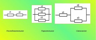
The following types are distinguished:
- sequential;
- parallel;
- mixed connection.
The electrical circuits of radio-electronic devices contain the most conductors and capacitors. Among all the properties, one parameter is of decisive importance:
- for conductors - resistance;
- for capacitors - capacitance.
With different methods of inclusion in the circuit, the total, resulting value is important; the difference in ratings is not critical.
Current sources are characterized by two parameters:
- electromotive force (EMF) E;
- internal resistance r.
Parallel connection of power sources with different emfs to the load has a serious drawback: even in the absence of an external load, a source with a higher electromotive force is discharged through a source with a lower emf. The process continues until the EMF values become the same, part of the total capacitance is lost.
In electrical engineering, parallel connection of power sources with different characteristics is used to operate on a common load, but not directly.
To be included in the circuit, complex alignment, synchronization, blocking, and protection circuits are used.
In everyday life, parallel installation of several identical galvanic elements is used: in flashlights, control panels for equipment, in radio-controlled toys.
They connect poles of the same name: plus with plus, minus with minus.
Such inclusion does not require any additional switches or security elements. The EMF between the poles of all sources is equal:
Egen = E1 = E2.
The total current increases, it is equal to the sum of the currents from each source:
Igen = I1+ I2.
Hydraulic analogy
A simple parallel for an electrical circuit in the voltage change formula is water flowing through a closed pipeline driven by a mechanical pump. This can be called a "water loop". The potential difference between two points corresponds to the difference in pressure between them. If the pump creates a pressure difference, then the water flowing from one flask to the other can do work, such as driving a turbine. Similarly, work can be done by an electric current controlled by the potential difference provided by a battery. For example, a voltage that is sufficiently charged to a car battery can "push" a large current through the starter motor windings. If the pump is not running, it does not create a pressure difference and the turbine does not rotate. Likewise, if the car's battery is very weak or discharged, it will not turn the starter.
The hydraulic analogy is a useful way to understand many electrical concepts. In such a system, the voltage is calculated by the formula of pressure multiplied by the volume of the moved charge. In an electrical circuit, the work done to move particles or other carriers is equal to "electrical pressure" multiplied by the number of electrical particles moved. The greater the pressure difference between two points in relation to flow (potential difference or water pressure difference), the greater the distance between them (electric current or water flow).
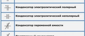
Parallel connection of capacitors
Regardless of the type of capacitor or the materials used to make it, it always consists of two main parts: plates. Their shape does not matter, but they may consist of a series of plates rolled into a roll.
For most types of capacitors, the plates are equal. The polarity of the current source connection is important for electrolytic devices.
The ability to accumulate and retain charges is characterized by a physical quantity – electrical capacity. It is defined as the ratio of the charge on the plates to the potential difference between them:
C = q/Δφ.
Designations:
- C – electrical capacitance, unit of measurement – farads (F);
- q – charge, measured in coulombs (C);
- Δφ – potential difference, measured in volts (V).
In practice, this quantity is more often called voltage:
Δφ = φ2 – φ1 = U.
The electrical capacity of the charge storage device depends on the size of the plates, the size of the gap between them, and the dielectric material. For a capacitor in the form of two plates, it looks like this:
C = (εε0S)/d.
Designations:
- ε – dielectric constant of the material located between the plates;
- ε0 – one of the physical constants (electrical constant);
- d – distance from one plate to another (dielectric thickness);
- S is their area.
When soldering in parallel, the voltage between the plates is the same. For a system of two elements:
Ugen = U1 = U2;
- Charges received:
q1 = C1U, q2 = C2U;
- Total charge:
qgen = q1 + q2;
- Then the total capacity:
Cgen = qgen/Ugen = (q1 + q2)/Ugen = q1/U1 + q2/U2 = C1 + C2.
When connected in parallel, the system capacitance is found as the sum of the capacitances of the individual charge storage devices.
Capacitors have one more characteristic: the voltage for which they are designed. It depends on the properties of the dielectric and its thickness.
It is possible to connect capacitors with different capacities and different operating voltages in parallel. The performance of the battery is determined by the element with the lowest voltage.
How to find voltage, formula. Electric field potential
An increase in voltage from some point xA at some point xB is given by someone.
In this formula for calculating voltage, the increase from point A to B is equal to the work that would have to be done per unit charge, against the electric field, to move the particle from A to B without causing any acceleration. Mathematically, this is expressed as the line integral of the electric field along this path. According to this definition, a voltage difference between two points is not uniquely formed when time-varying magnetic fields exist, since the electric force is not conservative in such cases.
If this definition of voltage is used, any circuit in which time-varying magnetic fields exist, such as rows containing inductors, will not have a well-defined voltage between nodes in the circuit. However, if the magnetic fields are properly contained in each component, then the electric field is conservative in the outer region and the components are well defined there. In this case, the voltage on the inductor, when viewed from the outside, appears.
Despite the fact that the internal electric field in the coil is zero (assuming it is an ideal conductor). There are several other ways to find out which voltage formula is needed in a particular case.
Parallel connection of resistors
The voltages at the ends of a group of connected conductors are equal for each resistor. For a two-element circuit:
Ugen = U1 = U2.
This formula is no different from the formula for the total voltage for two connected capacitors. The total current strength is found as the sum of the currents flowing through each section:
Igen = I1 + I2;
- For a section of the circuit, Ohm's law is satisfied:
I = U/R;
- For a group of two elements:
Igen = Ugen/Rgen = Ugen/R1 +Ugen/R2;
- Abbreviating Ugen, taking into account that the voltage value at the ends of each conductor is the same, we obtain:
1/Rgen = 1/R1 + 1/R2.
The reciprocal of the final resistance is equal to the sum of the reciprocals of the component resistances. The expression 1/R is called conductivity.
The total value is determined from the formula:
Rgen = R1R2/(R1 + R2).
When different conductors are arranged in parallel, the final resistance value decreases; it is less than the resistance of the element with the minimum rating.
For identical radioelements the formula is simpler:
Rgen = RR/(R + R) = R/2.
The total resistance value of 2 identical resistors is equal to 1/2 the nominal value of one of them.
In a parallel soldering circuit of K identical conductors, the total resistance is:
Rgen = R/K.
It is smaller by as many times as there are elements in the group.
Current resistance depends on the material from which the resistor is made, on its dimensions: length, thickness (sectional area). The dependence is expressed by the formula:
R = ρl/S.
In the formula:
- R – resistance in ohms (Ohm);
- l is the length of the resistor (wire);
- ρ – resistivity, measured in Ohm*m.
Due to the fact that the cross-section of real conductors is tens of mm2, Ohm*mm2/m is chosen as the unit of resistivity.
The value ρ shows the resistance of 1 m of conductor with a cross section of 1 mm2. Specific resistance is a tabular value.
Among the metals, silver has the lowest value - 0.016 Ohm*mm2/m, the highest is fechral: 1.3 Ohm*mm2/m.
Resistors have another important characteristic - energy dissipation power. This is the product of current and voltage.
More powerful radio components look thicker and rougher. All calculation formulas assume that elements of the same power are used in the circuit. The performance of a circuit in which elements with the same rating of different powers are used is determined by the lowest power resistor.
Knowledge of the peculiarities of connecting current sources, capacitors, and resistors helps to study the physical processes occurring in them, calculate electrical circuits, and determine the parameters of the optimal operating mode.
When creating real structures, it is important to select elements that are identical in at least one parameter. For current sources - this is the EMF, for capacitors - the voltage between the plates, for resistors - power.
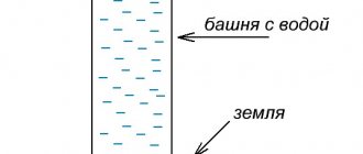
Example with ordinary water
This pressure potential is equivalent to voltage. The more water in the tank, the stronger the impact. The more powerful the charge stored in the battery, the higher the voltage.
When you open the hose, a stream of water flows. The pressure in the reservoir determines how quickly it drains. Electrical current is measured in amperes. The more volts, the stronger the A current. This means that the stronger the water pressure, the faster it will flow out of the tank.
You will be interested in:What is alkali, what reactions do the most famous of them undergo?
However, current also depends on resistance. In the case of a hose, this is its width. A wide pipe allows more water to pass through in less time, while a narrow pipe resists the flow of liquid. With electric current there can also be resistance, measured in ohms.
Galvani Potential
Within a conducting material, the energy of an electron is influenced not only by the average capabilities, but also by the particular thermal and atomic environment in which it is found. When a voltmeter is connected between two different types of metal, it does not measure the difference in electrostatic potential.
The quantity measured by a voltmeter is negative and is usually called the voltage difference. While the net uncorrected electrostatic capability (not measured by a voltmeter) is sometimes called Galvanic. The terms "voltage" and "electric potential" are ambiguous in the sense that in practice they can refer to either in different contexts.
Source