GENERAL ELECTRICAL ENGINEERING AND ELECTRONICS. ELECTRICITY AND MAGNETISM
|
Inductor
- is a passive component of electronic circuits, the main purpose of which is to store energy in the form of a magnetic field. The property of an inductor is somewhat similar to a capacitor, which stores energy in the form of an electric field.
Inductance (measured in Henry) is the effect of creating a magnetic field around a current-carrying conductor. The current flowing through the inductor creates a magnetic field, which has a relationship with the electromotive force (EMF) that opposes the applied voltage.
The resulting reaction force (EMF) opposes the change in alternating voltage and current in the inductor. This property of an inductive coil is called inductive reactance. It should be noted that the inductive reactance is in antiphase to the capacitive reactance of the capacitor in the AC circuit. By increasing the number of turns, the inductance of the coil itself can be increased.
Parallel connection of a capacitor
⇐ PreviousPage 6 of 7Next ⇒
And inductors.
The concept of current resonance
When an alternating sinusoidal voltage U is applied to a circuit (Fig. 8.1) with a parallel connection of a capacitor and an inductor, the same voltage is applied to both elements of the circuit.
Rice. 8.1
The total circuit current I branches into the current in the capacitor IC (the capacitive component of the total current) and the current in the coil IL (the inductive component of the total current), with the current IL lagging behind the voltage U by 90°, and IC leading by 90°.
Currents IC and IL have opposite phases (180°) and, depending on their magnitudes, balance each other completely or partially. They can be represented using vector current diagrams.
current resonance occurs
(vector diagram Fig. 8.2)
Rice. 8.2 Fig. 8.3 Fig. 8.4
When IC > IL, i.e. The capacitor current predominates, the total circuit current I is capacitive in nature and leads the voltage U by 90º (Fig. 8.3).
When IC < IL, i.e. the coil current prevails, the total circuit current I is inductive and lags behind the voltage U by 90° (Fig. 8.4).
These arguments were carried out neglecting the losses of active power in the capacitor and coil.
When currents resonate, the reactive conductivity of the circuit B = BL - BC is zero. The resonant frequency is determined from the equation:
from where, just as with voltage resonance,
The total conductivity at resonance of currents turns out to be close to zero. Only a small active
conductivity due to the active resistance of the coil and imperfect insulation of the capacitor. Therefore, the current in the unbranched part of the circuit has a minimum value, while the currents IL and IC can exceed it tens of times.
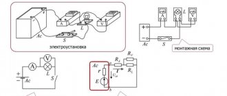
experimental part
Exercise
For a circuit with a parallel connection of a capacitor and an inductor, measure the effective values of the voltage U and currents I, IC and IL at Construct phasor diagrams.
Work order
• Assemble the circuit according to the diagram (Fig. 8.5), connect an adjustable sinusoidal voltage source and set its parameters: U= 7 V, f = 500 Hz. As an inductance with low active resistance, use a 300-turn transformer coil, inserting strips of paper in one layer (non-magnetic gap) between the horseshoes of the split core.
Rice. 8.5
• By changing the frequency of the applied voltage, achieve resonance at the minimum current I. For fine tuning, keep the voltage at the circuit input constant. When measuring with virtual instruments, the resonance is adjusted by the transition through zero of the phase angle between the input current and voltage. Then it is not necessary to maintain the voltage at the input of the circuit constant.
• Take measurements and record the measurement results in Table 8.1 at f = f0, f1≈0.75f0 and f2 ≈l.25f0.
Table 8.1
Construct the vector diagrams in Figure 8.6 on the same scale for each of the cases considered.
Rice. 8.6
Control questions:
- Why is resonance in a parallel circuit called current resonance?
- In what ways can current resonance be achieved?
- What is the resonant frequency?
- Will the total current necessarily decrease if a capacitor is connected in parallel with the coil?
- What is the application of current resonance?
- What do resonance curves look like?
- What are the conditions for current resonance?
- Draw vector diagrams for various operating modes of the electrical circuit under study at
- What is the peculiarity of currents in branches during current resonance?
- How can one experimentally determine and record the resonance of currents?
- How does the shape of the resonance curves change in the case of current resonance with increasing active resistance of the circuit under study?
- What is the purpose of trying to increase the power factor? Name ways to increase it.
Laboratory work No. 9 T three-phase load connected in a star configuration
In real three-phase generators, the windings often have one common point at which the ends of the windings X,Y,Z are connected. This connection diagram is called a star, and the common point of the windings is the zero point or neutral of the generator. The generator is connected to the energy receiver by three or four wires. Three of them, called linear, are connected to the beginnings of the windings (terminals A, B, C), and the fourth - zero or neutral - is connected to the zero point. Systems without a neutral wire are also used.
The voltages between linear wires ( i.e., between the beginnings of the generator windings ) are usually called linear and denoted by ,, and the order of the indices indicates the positive direction of the voltage in the external circuit. The voltages between the linear and neutral wires (i.e., between the beginnings and ends of the windings) are called phase voltages and are designated . Phase voltage differs from phase emf. by the magnitude of the drop in the generator winding. Let us establish the relationship between linear and phase voltages when connecting the generator windings with a star. The instantaneous values of linear and phase voltages are equal to the differences in the instantaneous potential values of the beginnings and ends of the corresponding windings:
Since the ends of the windings are connected to one point, the potentials
,
and instantaneous line voltage between points A and B
Similarly, line voltages
Thus, the instantaneous values of linear voltages are equal to the algebraic differences of the instantaneous values of the corresponding phase voltages.
If voltages are expressed in complex quantities, then the complex linear voltage is defined as the difference between the corresponding complex phase voltages:
.
In the same way, the linear voltage vectors are equal to the differences in the phase voltage vectors. Linear voltage vectors always form a closed triangle, since the sum is identically equal to zero. This will become obvious if the linear voltage vectors are moved parallel to themselves.
Looking at the diagrams, we see that the vectors of two adjacent phase voltages, together with the vector of the corresponding line voltage, form a closed triangle. With a symmetrical stress system, this triangle is isosceles, its angles are 30, 30 and 120. Therefore:
a) there is a relationship between the effective values of phase and linear voltages
or
i.e., the linear voltage is times greater than the phase voltage;
b) the vector diagram of symmetrical linear voltages is shifted by 30 degrees in the direction of vector rotation relative to the phase voltage diagram.
If the loads (receivers) are connected in a three-phase circuit in a star circuit with a neutral wire (Fig. 9.1), then phase voltages are applied to the load resistances.
Linear currents are equal to phase currents and are determined by Ohm’s law:
With symmetrical voltages UA, UB, UC and equal resistances RA=
RB = RC = R currents IA, IB, IC are also symmetrical and their vector sum (In) is zero. Then
If the load phase resistances are not the same, then some current IN=0 flows through the neutral wire. This is explained in vector diagrams (Fig. 9.2). a) symmetrical load b) asymmetrical load
The power of a three-phase load is the sum of the phase powers: ∑P = PA + PB + PC When the load is symmetrical and purely resistive, we have
With a mixed (active-inductive or active-capacitive) load
Active power
Reactive power
Full power
experimental part
Exercise
For a three-phase circuit with a star connection with symmetrical and asymmetrical loads, use a multimeter to measure the effective values of currents IЛ and IN, as well as voltages UЛ and UФ, calculate the powers RF and ∑PF, draw vector diagrams.
⇐ Previous6Next ⇒
Recommended pages:
Stored energy in inductance
As you know, a magnetic field has energy. Just as there is a reserve of electrical energy in a fully charged capacitor, there is also a reserve of magnetic energy in an inductive coil through the winding of which current flows.
The energy stored in the inductor is equal to the expended energy necessary to ensure the flow of current I in counteracting the EMF. The amount of stored energy in the inductance can be calculated using the following formula:
where L is the inductance, I is the current flowing through the inductor.
Hydraulic model
The operation of an inductor can be compared to the operation of a hydraulic turbine in a flow of water. The flow of water directed through a turbine that has not yet been spun up will feel resistance until the turbine is completely spun up.
Next, the turbine, which has a certain degree of inertia, rotates in a uniform flow, practically without affecting the speed of water flow. If this flow is suddenly stopped, the turbine will still rotate by inertia, creating water movement. And the higher the inertia of a given turbine, the more it will resist changes in flow.
Also, an inductive coil resists changes in the electric current flowing through it.
Inductance in electrical circuits
While a capacitor resists changes in alternating voltage, inductance resists alternating current. An ideal inductance will have no resistance to direct current, however, in reality, all inductive coils themselves have a certain resistance.
In general, the relationship between the time-varying voltage V(t) passing through a coil of inductance L and the time-varying current I(t) passing through it can be represented as a differential equation of the following form:
When a sinusoidal alternating current (AC) flows through an inductor, a sinusoidal alternating voltage (EMV) is generated. The amplitude of the EMF depends on the amplitude of the current and the frequency of the sinusoid, which can be expressed by the following equation:
where ω is the angular frequency of the resonant frequency F:
Moreover, the phase of the current lags behind the voltage by 90 degrees. In a capacitor, the opposite is true, where the current leads the voltage by 90 degrees. When an inductive coil is connected to a capacitor (series or parallel), an LC circuit is formed that operates at a specific resonant frequency.
Inductive reactance XL is determined by the formula:
where XL is the inductive reactance, ω is the angular frequency, F is the frequency in hertz, and L is the inductance in henry.
Inductive reactance is the positive component of impedance. It is measured in ohms. The impedance of the inductor (inductive reactance) is calculated by the formula:
Series connection of circuit elements at alternating voltage
Let's start with a series connection of resistance R, inductance L and capacitance C and consider the effect on it of alternating voltage with frequency ω.
Series connection of circuit elements.
In this circuit, the input alternating voltage U, in accordance with Kirchhoff’s second law, will be equal to the algebraic sum of the alternating voltages on the individual elements
where UR, UL, UC are the voltage across the circuit elements, resistance R, inductance L and capacitance C, respectively,
Im – amplitude value of alternating current.
A graphical representation of voltages and currents on series-connected circuit elements is presented below
Voltages and currents in series connection.
The final expression is a trigonometric form of Kirchhoff's second law for instantaneous stresses and can be rewritten as
where R is active resistance,
X – reactance.
The value of active resistance R is always only positive, and reactance X can take either a positive value X > 0, in which case it is inductive in nature , or a negative value X < 0, in which case the reactance is capacitive in nature .
voltage resonance occurs
In this case, the circuit resistance is represented only by the active load R, and therefore the phase shift between voltage and current will be zero.
When making calculations, we are interested not so much in the current and voltage on individual elements, but in the current and voltage of the entire circuit. To do this, we will continue to convert the voltage
where Z is the total resistance of the circuit,
ψ – phase difference between voltage and current.
Thus, the amplitude value of the voltage Um and the amplitude value of the current Im are related to each other by the following relation
where Um is the amplitude value of the alternating voltage,
Im – amplitude value of alternating current,
Z is the total resistance of the circuit.
Inductor connection diagrams
Parallel connection of inductors
The voltage across each of the inductors connected in parallel is the same. The equivalent (total) inductance of parallel-connected coils can be determined by the formula:
Series connection of inductors
The current flowing through inductors connected in series is the same, but the voltage across each inductor is different. The sum of potential differences (voltages) is equal to the total voltage. The total inductance of series-connected coils can be calculated using the formula:
These equations are valid provided that the magnetic field of each coil does not affect neighboring coils.
Unit converter
1 mH = 0.001 G. 1 μH = 0.000001 = 10⁻⁶ H. 1 nH = 0.000000001 = 10⁻⁹ H. 1 pH = 0.000000000001 = 10⁻¹² G. Learn more about inductance units.
Inductance characterizes the ability of an electrical conductor to convert electric current into a change in electrical potential in a given conductor (self-inductance) and in adjacent conductors (mutual inductance). Inductance is usually denoted by the symbol L in honor of the German-born Russian physicist Emilius Christianovich Lenz.
By definition of self-induction, voltage v(t)
and current
i(t)
in the inductor are related by the expression
All inductors connected in parallel have the same voltage V
.
According to Kirchhoff's rule for current, the total current I
is equal to the sum of the currents flowing through the individual coils:
The total inductance Leq of three inductors connected in parallel, located far from each other and not having a common magnetic field, is equal to the reciprocal of the sum of the reciprocals of their inductances:
Or for n
uncoupled inductors:
This formula for L
eq is used for calculations in this calculator. For example, the total inductance of three 10, 15 and 20 µH inductors connected in parallel would be
µH
Note that if one or more inductance values are zero, then Leq tends to zero. Imagine a very short straight conductor shunting an inductor - it will have almost zero inductance. Note also that it is impossible to create a circuit with zero inductance. If only two inductors are connected in parallel, we have:
or
Equivalent inductance n
identical inductors connected in parallel,
L
is equal to
Note that the formula for calculating the total inductance of several inductors connected in parallel is also used to calculate the resistance of a group of resistors connected in parallel.
Note also that for a group of any number of inductors connected in parallel, the equivalent inductance will always be less than the smallest inductance in the group of inductors, and adding another inductor will always reduce the equivalent inductance of the group.
Toroidal inductors in the printer power module
If the inductors are located in each other's magnetic field, these formulas will not work due to the phenomenon of mutual induction (mutual induction)
, which is covered in our mutual induction calculator. The mutual inductance effect can reduce or increase the total inductance of the coils depending on how the magnetic coupling between the coils works. The amount of mutual induction depends on the distance between the coils and their orientation. In this case, mutual inductance can increase or decrease the total inductance.
If several inductors are connected in series
, their equivalent inductance is determined by simply adding the inductances of the individual coils.
For n
inductors connected in series we have
You may have already noticed that inductors behave exactly like resistors: if the coils are connected in series, their equivalent inductances will always be higher than the inductances of the individual coils connected in series, and when connected in parallel, the equivalent inductance will always be less than the inductances of the individual coils .
Multilayer stacked helical inductor in a microcircuit and its simplified equivalent circuit
Why connect the coils in series when you can just wind a large inductor? Here is one example.
In microelectronics, to realize fairly large inductances per unit area of an integrated circuit, a combination of spiral coils in several layers of metallization is used. A multilayer stacked inductor configuration is used for this purpose. Several layers of metallization with spiral coils are placed exactly one above the other. The coils are connected in series so that the inductors add up to form one large inductor. Without such a stacked arrangement, it would be impossible to create large inductors using planar technology. Thanks to this stacked arrangement, the coil coupling coefficient k
≈ 1.
In this calculator we only consider ideal inductors. However, we live in the real world, where real coils have both resistance and capacitance. In another calculator, we will look at the characteristics of non-ideal inductors with resistance, which are described by an equivalent circuit of inductance and resistance connected in series, in particular their timing characteristics.
Frameless coreless inductors in RF module
Author of the article: Anatoly Zolotkov
Inductor quality factor
In practice, an inductor has a series resistance created by the copper winding of the coil itself. This series resistance converts the electric current flowing through the coil into heat, which leads to a loss of induction quality, that is, quality factor. Quality factor is the ratio of inductance to resistance.
The quality factor of the inductor can be found through the following formula:
where R is the winding's own resistance.
Consistent and counter connection of inductances
The conclusions of two inductively coupled coils, relative to which the currents are directed in the same way and the directions of the self-induction and mutual induction flows they create in each coil coincide, are called the same , and the connection of the coils is consonant. In other words, the terminals of the same name of two coils have the peculiarity that the supply of an increasing current to one of them leads to an increase in the potential at the terminal of the same name of the other coil.
If the flows are directed counter, then the terminals of the coils, relative to which the directions of the currents coincide, are called opposite , and the connection of the coils is called counter. On circuit diagrams, terminals of the same name are designated by some identical sign, for example, an “asterisk” (*), a dot, or another.
Rice. 12.2. Consistent (a, c) and counter (b, d) connection of inductors
In connection with the introduction of the concept of terminals of the same name, when drawing electrical circuits, there is no need to show the winding of the turns of inductors, but it is enough to mark their terminals of the same name and the selected positive directions of currents on the diagram (Fig. 12.2).
A comprehensive form for calculating circuits with mutual inductances
We connect two inductively coupled coils in series so that the total magnetic flux of each coil increases, that is, we turn on the coils according to (Fig. 12.2, c).
Based on Faraday's law, the self-induction emf of the first coil in complex notation is equal to
The electromotive force of mutual induction when the coils are switched on in agreement will have the same sign as , that is
Similar relationships exist for the second inductance.
Considering that , let’s create an equation to find the voltage in the case of coordinated connection of the coils:
Since , we get
Where .
When the inductors are switched on in series (Fig. 12.2, d), the voltage equation at the circuit terminals will be equal to:
Where .
In Fig. Figure 12.3 shows topographic vector diagrams for a consonant and counter series connection of two inductors.
The last two equations indicate the method for finding the value of mutual induction. To do this, you need to measure the reactive components of the impedances with consonant and counter-connected inductances and subtract them
Rice. 12.3. Vector diagrams of inductively coupled coils connected in series according to (a) and counter (b)
From here we get the expression
which allows one to calculate the value of mutual induction from experimental data.
Inductor. Inductance formula
Basic formula for coil inductance
- L = inductance in henry
- μ 0 = permeability of free space = 4π x 10 -7 H/m
- μ g = relative permeability of core material
- N = number of turns
- A = Cross-sectional area of the coil in square meters (m2)
- l = coil length in meters (m)
Direct conductor inductance
- L = inductance in nH
- l = conductor length
- d = conductor diameter in the same units as l
Air core coil inductance
- L = inductance in µH
- r = outer coil radius
- l = coil length
- N = number of turns
Inductance of Multilayer Air Core Coil
- L = inductance in µH
- r = average coil radius
- l = coil length
- N = number of turns
- d = coil depth
Flat Coil Inductance
- L = inductance in µH
- r = average coil radius
- N = number of turns
- d = coil depth
Inductor design
An inductor is a winding of conductive material, usually copper wire, wound around either an iron-containing core or no core at all.
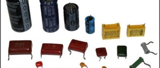
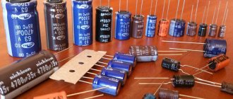
The use of materials with high magnetic permeability, higher than air, as a core helps to retain the magnetic field near the coil, thereby increasing its inductance. Inductive coils come in different shapes and sizes.
Most are made by winding enameled copper wire over a ferrite core.
Some inductive coils have an adjustable core that allows the inductance to vary.
Miniature coils can be etched directly onto the PCB in a spiral pattern. Low-value inductors can be located in microcircuits using the same technological processes used to create transistors.
Application of inductors
Inductors are widely used in analog and signal processing circuits. They combine with capacitors and other radio components to form special circuits that can amplify or filter signals of a specific frequency.
Inductors have a wide range of applications ranging from large inductors such as power supply chokes that, in combination with filter capacitors, eliminate residual noise and other oscillations in the power supply output, to as small inductors as those found inside integrated circuits.
Two (or more) inductors, which are connected by a single magnetic flux, form a transformer, which is the main component of circuits operating with an electrical power supply network. Transformer efficiency increases with increasing voltage frequency.
For this reason, aircraft use AC voltage with a frequency of 400 hertz instead of the usual 50 or 60 hertz, which in turn allows for significant savings in the mass of transformers used in the aircraft power supply.
Inductors are also used as energy storage devices in switching voltage stabilizers, in high-voltage electrical power transmission systems to deliberately reduce system voltage or limit short-circuit current.
Calculation of inductors
Any conductor carrying current creates a magnetic field around itself. The ratio of the magnetic flux of this field to the current generating it is called inductance. The inductance of a straight piece of conductor is small and amounts to 1...2 µH per meter of length, depending on the diameter of the wire (thin conductors have a higher inductance). The formula gives more accurate results
where is the length of the wire; d is its diameter. Both sizes must be taken in meters (under the logarithm sign it is permissible in any, but identical units), the inductance will be in microhenry. To make calculations easier, recall that the natural logarithm of any number is 2.3 times the decimal logarithm (which can be found using tables, a slide rule or a calculator), i.e. Inx = 2.3lgx.
Why did we give this formula? Let's explain with an example.
Let the leads of a certain radio element have a length of 4 cm and a diameter of 0.4 mm. Let's calculate their inductance:
2.3lg100 = 4.6 and 0.2-0.04-3.6 = 0.03 (rounded).
So, the inductance of each pin is close to 0.03 μH, and the inductance of two pins is 0.06 μH. With a capacitance of only 4.5 pF (and the mounting capacitance can be higher), such an inductance forms an oscillating circuit tuned to a frequency of 300 MHz - remember Thomson’s formula:
f = 1/2π√LC.
This is why installation on VHF cannot be done with long wires and long leads of parts should not be left.
To increase the inductance, the conductor is rolled into a ring. The magnetic flux inside the ring increases, and the inductance becomes approximately three times greater:
L = 0.27πD(ln8D/d-2).
Here D is the diameter of the ring, the dimensions are the same. A further increase in inductance occurs with an increase in the number of turns, while the magnetic fluxes of individual turns not only add up, but also affect all other turns. Therefore, inductance increases in proportion to the square of the number of turns. If there are N turns in the coil, the inductance obtained for one turn must be multiplied by N2.
For a single-layer cylindrical coil with a length much greater than the diameter D (Fig. 23), the inductance is calculated quite accurately using the formula
strictly derived for a very long solenoid or torus. All dimensions here are in the SI system (meters, Henry), μ0 = 4π·10-7 H/m - magnetic constant; S = πD2/4 is the cross-sectional area of the coil; μ is the effective magnetic permeability of the magnetic circuit. For open magnetic cores, it is significantly less than the permeability of the material itself. For example, for a magnetic antenna rod made of ferrite grade 600NN (magnetic permeability 600) and barely reaches 150. If there is no magnetic circuit, μ = 1.
This formula gives very accurate results for toroidal coils, and l
corresponds to the circumference of the ring magnetic circuit, measured along its center line. The formula is also suitable for low-frequency transformers wound on an W-shaped magnetic core (Fig. 24).
In this case, S = ab is the cross-sectional area of the magnetic core, and l
is the average length of the magnetic field line, shown in the dotted line in the figure.
For closed magnetic cores assembled without a gap, as for ferrite rings, and is taken equal to the magnetic permeability of the material. A small gap slightly reduces μ. Its influence can be taken into account by increasing the length of the magnetic field line l
by the value δμ, where δ is the gap width, μ is the magnetic permeability of the core material.
As you can see, inductance practically does not depend on the diameter of the wire. For low-frequency coils, the wire diameter is selected based on the permissible current density, for copper conductors 2...3 amperes for each mm2 of conductor cross-section. In other cases, especially with RF coils, one strives to obtain a minimum conductor resistance in order to increase the quality factor (the ratio of inductive to active reactance).
For this purpose, it would seem that it is necessary to increase the diameter of the wire, but then the length of the winding increases, which reduces the inductance, and with a close, multi-layer arrangement of turns, the effect of “displacing” the current from the winding is observed, which increases the resistance. The effect is similar to current displacement at high frequencies in any conductor, resulting in current flowing only in a thin skin layer near the surface of the conductor. The skin layer thickness decreases, and the wire resistance increases in proportion to the square root of the frequency.
Thus, to obtain the required inductance and quality factor, it is not at all necessary to choose the thickest wire. For example, if a single-layer coil (see Fig. 23) is wound with thick wire turn to turn or with twice as thin wire, but with a step equal to the diameter of the wire, the inductance will remain the same and the quality factor will hardly decrease. The quality factor increases as all dimensions of the coil increase along with the diameter of the wire, mainly its diameter.
To obtain maximum quality factor and inductance, it is more advantageous to make the coil short, but of large diameter, with a ratio D/ l
about 2.5. The inductance of such coils is more accurately calculated using the empirical (experimentally selected) formula
where the dimensions are taken in centimeters, and the inductance is obtained in microhenry. Interestingly, the same formula applies to a spiral or basket flat coil (Fig. 25).
The average diameter is taken as D:
D = (Dmax + Dmin)/2
and as l
- winding width,
l
= (Dmax - Dmin)/2.
The inductance of a multilayer coil without a core (Fig. 26) is calculated by the formula
where the dimensions are substituted in centimeters, and the inductance is obtained in microhenry. With dense ordinary winding, the quality factor does not exceed 30...50, “loose” winding (in bulk, universal) gives high quality factor values. Even better is the “cellular” winding, now almost forgotten. At frequencies up to 10 MHz, the quality factor increases when using Litz wire - a wire twisted from many thin insulated strands. Litz wire has a larger total wire surface, through which current actually flows due to the skin effect, and therefore has less resistance at high frequencies.
A magnetodielectric trimmer increases the inductance up to 2-3 times, depending on the size of the trimmer. An even greater increase in inductance is provided by closed or partially closed magnetic circuits, for example, pot-shaped ones. In this case, it is better to use the strict formula for a solenoid or torus (see above). The quality factor of a coil on a closed magnetic circuit is determined not so much by the wire as by losses in the core material.
To conclude the chapter, we present several useful formulas for calculating the active resistance of wires. The linear resistance (per meter of length) of a copper wire at direct current and low frequencies (Ohm/m) can be easily found using the formula
FL = 0.0223/d2,
where d is the diameter of the wire, mm. Skin thickness for copper (mm) is approximately 1/15√ f
(MHz). Please note: already at a frequency of 1 MHz, the current penetrates the wire to a depth of only 0.07 mm! In the case where the wire diameter is greater than the skin layer thickness, the resistance increases compared to the resistance at direct current. The linear resistance of the wire at high frequency is estimated using the formula
R = √f/12d (mm).
Unfortunately, these formulas cannot be used to determine the active resistance of coils, since due to the effect of the proximity of the turns, it turns out to be even greater.
Connections of resistors, capacitors and inductors
Series and parallel connections in electrical engineering are the two main ways of connecting elements of an electrical circuit. In a series connection, all elements are connected to each other in such a way that the section of the circuit that includes them does not have a single node. In a parallel connection, all elements included in the chain are united by two nodes and have no connections with other nodes, unless this contradicts the condition.
When conductors are connected in series, the current in all conductors is the same. In a parallel connection, the voltage drop between the two nodes connecting the elements of the circuit is the same for all elements. In this case, the reciprocal value of the total resistance of the circuit is equal to the sum of the reciprocal values of the resistances of parallel-connected conductors.
When connecting resistors R1, R2, ..., Rn
the total resistance of the circuit is equal to the sum of the resistances of the individual resistors:
Rtot = R1 + R2 + … + Rn
With parallel connection n
resistors, the conductivity of the entire circuit is equal to the sum of the conductivities of all resistors (based on the expression given below, you can determine the resistance of the circuit when connecting n resistors in parallel):
1/Rtotal = 1/R1 + 1/R2
+ … + 1/Rn
With parallel connection n
capacitors, the total capacitance of the circuit is equal to the sum of the capacitances of the individual capacitors:
Commun = C1 + C2 + … + Cn
With serial connection n
capacitors their total capacity:
1/Comm = 1/C1 + 1/C2 + … + 1/Cn
With serial connection n
inductors, without mutual inductance, the total inductance of the circuit is equal to the sum of the inductances of the individual coils:
Ltotal = L1
+ L2 + … + Ln
With parallel connection n
inductance coils, without mutual inductance, the total inductance of the entire circuit is determined by the formula:
1/Ltot = 1/L1 + 1/L2 + …
+ 1/Ln
If the magnetic field of one coil intersects the turns of the other, i.e. the coils have mutual inductance, then when two coils are connected in series, the total inductance is:
Ltot
= L 1 + L 2 ±
2M ,
where M
– mutual induction (Gn).
When connecting two coils in parallel:
Ltot =
( L 1 ∙ L 2 – M 2) / ( L 1 ∙ L 2 ± 2M)
,
where is the plus sign in front of the 2M
set when the coils are turned on in agreement, and minus when the coils are turned on in the opposite direction;
mutual induction: M = k ∙ √ ( L 1
∙ L 2 )
,
where k
– coupling coefficient (
k > 1
), which depends on the relative position of the inductors
L 1
and
L 2
, the method of winding the inductors, etc.
Toroidal coil inductance (µH):
L
= 4 ∙ ∏ ∙ µ ∙ F ( ω 2 / l ) ∙ 10-3
,
where ω
– number of turns;
µ
– absolute magnetic permeability of the material;
F
– cross-sectional area of the magnetic circuit (cm2);
l
– average length of the magnetic line (cm).
Inductance of a single-layer cylindrical coil at l > 0.3D
:
L
= ω 2 ∙ D 2 / (100 ∙ l + 45 ∙ D )
,
where l
– coil length (cm);
D
– coil diameter (cm).