General definitions
The physical process in which charged particles move in an orderly (directional) manner is called electric current. It is usually divided into variable and constant. For the first, the direction and magnitude remain unchanged, but for the second, these characteristics change according to a certain pattern.
The above definitions are greatly simplified, although they explain the difference between direct and alternating current. To better understand what this difference is, it is necessary to provide a graphical representation of each of them, as well as explain how the alternating electromotive force is generated in the source. To do this, let us turn to electrical engineering, or rather its theoretical foundations.
Shipping Differences
When current flows, some of the electron energy is converted into heat due to the active resistance of the wires. Electric heaters are also based on this effect. At the end of the line, less energy is transferred to the consumer. The dissipated power is called losses. To reduce losses, voltage increases during transportation are used. These physical relationships apply to both direct and alternating current, but differences arise when implementing transmission circuits.
Advantages and disadvantages of alternating current
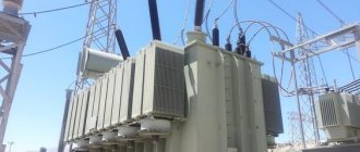
When the construction of transmission power networks began, the use of transformers was the only way to obtain high voltages and then reduce them to the required level when distributed to consumers. This technology was called transformer technology, and until now the structure of electricity transportation has not changed. Alternating current, which is a three-phase system, is almost universally used.
AC power lines
Later, direct current lines began to be constructed, which have been used more and more widely in recent years. The increased interest in their use is explained by the significant disadvantages of alternating current systems: in long lines, electricity losses are significant. Their reasons are the presence of capacitive and inductive reactances.
- When the direction of electron flow quickly changes, an effect similar to the recharging of capacitors is observed. Additional capacitive currents arise. This especially affects land and submarine cables, the insulating layer of which has a high capacitor effect;
- Inductive reactance of lines appears because electric currents generate magnetic fields that change with the frequency of the current. Inductive currents appear.
Important! Both types of reactance increase with increasing line length.
Advantages of alternating current:
- easy voltage transformation;
- possibility of combining different transmission systems;
- possibility of using system-wide frequency.
Disadvantages of AC:
- the need to compensate for reactive power when transporting over long distances;
- relatively high losses.
Advantages and disadvantages of DC
First of all, what distinguishes alternating current from direct current is the presence of sources of reactive energy losses. However, direct electric current involves heating losses. Their exact definition depends on the technology and voltage level. For high voltages - about 3% per 1000 km.
Another source of losses in DC power transmission systems are substations for converting AC to DC, and vice versa. The total losses are much lower than for alternating current, but the material costs for the construction of these substations are significant.
Equipment for high-voltage DC power lines
Important! To increase the profitability of DC power lines, long-length power lines are used.
DC power transmission has recently advanced technologically, with the development of new electronic components to create high DC voltage levels - high-performance thyristors or bipolar transistors.
Interesting. Today, DC transmission systems with voltages of up to 800 kV and transmission capacities of up to 8,000 mW over distances of more than 2,000 km are possible.
Advantages of high-voltage DC power lines:
- the ability to transmit power via submarine, land and underground cable lines over long distances;
- no losses due to reactive power;
- better use of cable insulation.
Disadvantages of high-voltage DC power lines:
- insufficiently fast switching of existing DC channels;
- little standardized electrical engineering;
- Distribution networks for electricity transmission are not developed; transportation is carried out from point to point.
EMF sources
Sources of electric current of any kind are of two types:
- primary, with their help, electricity is generated by converting mechanical, solar, thermal, chemical or other energy into electrical energy;
- secondary, they do not generate electricity, but convert it, for example, from variable to constant or vice versa.
The only primary source of alternating electric current is a generator; a simplified diagram of such a device is shown in the figure.
Simplified illustration of generator design
Designations:
- 1 – direction of rotation;
- 2 – magnet with poles S and N;
- 3 – magnetic field;
- 4 – wire frame;
- 5 – EMF;
- 6 – ring contacts;
- 7 – current collectors.
Definition
Electric current is the directional movement of charged particles.
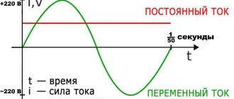
This is the definition from a physics textbook. In simple words it can be translated that its components always have some kind of direction. Actually, this direction is decisive in today's conversation. Alternating current (AC) differs from direct current (DC) in that the latter's electrons (charge carriers) always move in one direction. Accordingly, the difference between alternating current is that the direction of movement and its strength depend on time. For example, in a socket, the direction and magnitude of the voltage, respectively the current, changes according to a sinusoidal law with a frequency of 50 Hz (the polarity between the wires changes 50 times per second).
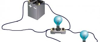
For electricians, so to speak, we will depict this on a graph, where the vertical axis shows polarity and voltage, and the horizontal axis shows time:
The red line shows a constant voltage; it remains unchanged over time, except that it changes when switching a powerful load or a short circuit. Green waves show sinusoidal current. You can see that it flows in one direction or the other, unlike direct current, where electrons always flow from minus to plus, and the direction of movement of the electric current is chosen to be from plus to minus.
To put it simply, the difference in these two examples is that the constant's plus and minus are always on the same wires. If we talk about alternating, then in power supply the concepts of phase and zero are used. If we look at it by analogy with a constant, then phase and zero are plus and minus, only the polarity changes 50 times per second (in the USA and a number of other countries 60 times per second, and in airplanes more than 400 times).
Principle of operation
Mechanical energy is converted by the generator shown in the figure into electrical energy as follows:
Due to such a phenomenon as electromagnetic induction, when the frame “4” rotates, placed in the magnetic field “3” (arising between the different poles of the magnet “2”), an emf “5” is formed in it. Voltage is supplied to the network through current collectors “7” from ring contacts “6”, to which frame “4” is connected.
Video: direct and alternating current - differences
As for the magnitude of the EMF, it depends on the speed of intersection of the power lines “3” by the frame “4”. Due to the characteristics of the electromagnetic field, the minimum crossing speed, and therefore the lowest value of the electromotive force, will be at the moment when the frame is in a vertical position, respectively, the maximum - in a horizontal position.
Taking into account the above, in the process of uniform rotation an emf is induced, the characteristics of the magnitude and direction of which change with a certain period.
Disadvantages of DC
The following shortcomings follow from the above.
- The difficulty of increasing and decreasing voltage, that is, converting DC electricity. This is primarily due to the complexity of the converter designs. Because powerful semiconductor switches designed for high voltage are needed. The absence of which leads to a large number of series and parallel connected semiconductor devices. As a result, the reliability of the entire converter decreases, the cost increases and power losses increase.
- Electric machines have a more complex design, therefore they are less reliable and more expensive, both in production and in operation.
- Difficulties in decoupling high and low voltages.
Graphic images
Thanks to the use of the graphical method, it is possible to obtain a visual representation of dynamic changes in various quantities. Below is a graph of voltage changes over time for a 3336L (4.5 V) galvanic cell.
The horizontal axis displays time, the vertical axis shows voltage
As you can see, the graph is a straight line, that is, the source voltage remains unchanged.
Now we present a graph of the dynamics of voltage changes during one cycle (full revolution of the frame) of the generator.
The horizontal axis displays the angle of rotation in degrees, the vertical axis displays the magnitude of the emf (voltage)
For clarity, we will show the initial position of the frame in the generator, corresponding to the starting point of the report on the graph (0°)
Frame initial position
Designations:
- 1 – magnet poles S and N;
- 2 – frame;
- 3 – direction of rotation of the frame;
- 4 – magnetic field.
Now let's see how the EMF will change during one cycle of rotation of the frame. At the initial position, the EMF will be zero. During the rotation process, this value will begin to increase smoothly, reaching a maximum at the moment when the frame is at an angle of 90°. Further rotation of the frame will lead to a decrease in the EMF, reaching a minimum at the moment of rotation by 180°.
Continuing the process, you can see how the electromotive force changes direction. The nature of the changes in the EMF that has changed direction will be the same. That is, it will begin to increase smoothly, reaching a peak at the point corresponding to a 270° rotation, after which it will decrease until the frame completes a full rotation cycle (360°).
If the graph is continued for several rotation cycles, we will see a sinusoid characteristic of alternating electric current. Its period will correspond to one revolution of the frame, and its amplitude will correspond to the maximum value of the EMF (forward and reverse).
Now let's move on to another important characteristic of alternating electric current - frequency. The Latin letter “f” is used to denote it, and its unit of measurement is hertz (Hz). This parameter displays the number of complete cycles (periods) of EMF change within one second.
The frequency is determined by the formula: . The “T” parameter displays the time of one complete cycle (period), measured in seconds. Accordingly, knowing the frequency, it is easy to determine the time of the period. For example, in everyday life an electric current with a frequency of 50 Hz is used, therefore, its period time will be two hundredths of a second (1/50 = 0.02).
Edison and Tesla
Hippolyte Pixie managed to create the first alternating current generator in 1835. It was a permanent magnet device that worked by rotating a handle. Entrepreneurs of that time were interested in DC generation and did not quite understand where the invention could be applied and why it was necessary to obtain AC.
The real competition for electrical transmission standards began in the late 1880s. years, when the struggle began between the major energy companies for dominance in the market for their own patented energy systems. It was a rivalry between the electrification concepts of two great inventors: Nikola Tesla and Thomas Edison.
Edison invented and improved many devices necessary for the first direct current generation and transmission systems. Within a short time, his company was able to open more than 200 stations in North America. The enterprise grew, and the inventor hired Nikola Tesla, a young engineer from Europe, to carry out work on improving the equipment. The new employee brought to Edison's attention revolutionary work for that time, based on variable value technologies. Tesla's ideas were rejected and the inventors went their separate ways.
George Westinghouse, on the contrary, reacted to the discoveries of the Serbian engineer with great interest and bought all Tesla's patents.
After the Westinghouse enterprise, it experienced many upheavals, including those associated with Edison’s powerful propaganda companies. The finale of the struggle came when Tesla's system was chosen to cover an exhibition in Chicago. This event introduced the world to the benefits of multiphase AC generation and transmission. Since then, most electrical devices and networks have been ordered to meet the new standard. The main dates of the War of Currents were:
- 1870 - Edison created the first DC generator;
- 1878 - Edison Electric Light Co. founded in New York;
- 1882 - Edison opened the Pearl Street generating station with 5 thousand lights;
- 1883 - Tesla invented the transformer;
- 1884 - Tesla invented the AC generator;
- 1888 - Tesla demonstrates a multiphase electrical system, Westinghouse buys his patents;
- 1888 - execution by electric chair, invented by Edison as a means of propaganda campaign demonstrating the dangers of Tesla's technology.
- 1893 - Westinghouse Electric Company triumphs at the Chicago Fair.
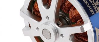
Three-phase generators
Note that the most cost-effective way to obtain alternating electric current is to use a three-phase generator. A simplified diagram of its design is shown in the figure.
Three-phase generator device
As you can see, the generator uses three coils, placed with an offset of 120°, connected to each other by a triangle (in practice, such a connection of the generator windings is not used due to low efficiency). When one of the poles of the magnet passes by the coil, an emf is induced in it.
Graphical representation of the generated three-phase electric current
Voltage formula
There is a formula in physics, although it has no practical application. The official formula is written like this.
voltage formula
Where
A is the work done by the electric field to move a charge along a section of the circuit, Joules
q - charge, Coulomb
U—voltage on a section of the electrical circuit, Volts
In practice, the voltage across a section of a circuit is derived through Ohm's law.
It will be interesting➡ What is meant by touch tension?
voltage from Ohm's law
Where
I - current, Amperes
R - resistance, Ohms
What is the reason for the variety of electric currents?
Many may have a well-founded question - why use such a variety of electric currents if you can choose one and make it standard? The thing is that not every type of electric current is suitable for solving a particular problem.
As an example, we give conditions under which using constant voltage will not only be unprofitable, but sometimes impossible:
- the task of transmitting voltage over distances is easier to implement for alternating voltage;
- it is almost impossible to convert direct electric current for heterogeneous electrical circuits that have an uncertain level of consumption;
- maintaining the required voltage level in direct current circuits is much more difficult and expensive than alternating current;
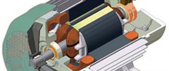
- motors for alternating voltage are structurally simpler and cheaper than for direct voltage. At this point, it should be noted that such motors (asynchronous) have a high level of starting current, which does not allow them to be used for solving certain problems.
Now we give examples of problems where it is more appropriate to use constant voltage:
- To change the rotation speed of asynchronous motors, you need to change the frequency of the power supply network, which requires complex equipment. For motors running on direct current, it is enough to change the supply voltage. That is why they are installed in electric vehicles;
- power supply of electronic circuits, galvanic equipment and many other devices is also carried out by direct electric current;
- DC voltage is much safer for humans than alternating voltage.
Based on the examples listed above, there is a need to use different types of voltage.
Conclusions: direct or alternating current
Despite all the advantages of direct current, the significant complexity caused by the conversion of large powers, mainly affecting the difficulty of increasing and decreasing the direct voltage, negates the above advantages. Therefore, until semiconductor switches of enormous power and corresponding converters based on them are developed, alternating current remains out of competition. In addition, four-quadrant converters or active rectifiers are now being used to compensate for the reactive component of the load, which makes it possible to obtain a power factor equal to almost unity. This eliminates the consumption of reactive power.
As you can see, there is no clear answer to the question of which current is better: direct or alternating. All advantages and disadvantages for a particular case should be compared.
A Brief History of Electricity
Who invented electricity? And no one! People gradually understood what it was and how to use it.
It all started in the 7th century BC, on one sunny (or maybe rainy, who knows) day. Then the Greek philosopher Thales noticed that if you rub amber on wool, it will attract light objects.
Then there were Alexander the Great, wars, Christianity, the fall of the Roman Empire, wars, the fall of Byzantium, wars, the Middle Ages, the Crusades, epidemics, the Inquisition and more wars. As you understand, people had no time for any electricity or ebonite sticks rubbed with wool.
In what year was the word “electricity” invented? In 1600, the English naturalist William Gilbert decided to write the work “On the Magnet, Magnetic Bodies and the Great Magnet - the Earth.” It was then that the term “electricity” appeared.
One hundred and fifty years later, in 1747, Benjamin Franklin, whom we all love very much, created the first theory of electricity. He viewed this phenomenon as a fluid or immaterial liquid.
It was Franklin who introduced the concept of positive and negative charges (before that, glass and resin electricity were separated), invented the lightning rod and proved that lightning is electrical in nature.
Everyone loves Benjamin, because his portrait is on every hundred dollar bill. In addition to his work in the exact sciences, he was a prominent political figure. But contrary to popular belief, Franklin was not the President of the United States.
Next will be a list of discoveries important for the history of electricity.
1785 - Coulomb finds out with what force opposite charges attract and like charges repel.
1791 - Luigi Galvani accidentally noticed that the legs of a dead frog contracted under the influence of electricity.
The operating principle of the battery is based on galvanic cells. But who created the first galvanic cell? Based on Galvani's discovery, another Italian physicist Alessandro Volta created the Volta column in 1800, the prototype of the modern battery.
At excavations near Baghdad, they found a battery more than two thousand years old. What ancient iPhone was recharged with its help remains a mystery. But we know for sure that the battery has already run out. This case seems to say: maybe people knew about electricity much earlier, but then something went wrong.
Already in the 19th century, Oersted, Ampere, Ohm, Thomson and Maxwell made a real revolution. Electromagnetism was discovered, induced emf, electrical and magnetic phenomena were linked into a single system and described by fundamental equations.
By the way! If you don’t have time to deal with all this yourself, our readers are now offering a 10% discount on any type of work
The 20th century brought quantum electrodynamics and the theory of weak interactions, as well as electric cars and ubiquitous power lines. By the way, the famous Tesla electric car runs on direct current.
Of course, this is a very brief history of electricity, and we have not mentioned very many names that influenced progress in this field. Otherwise, a whole multi-volume reference book would have to be written.
Types used
In most cases, what is called alternating current refers to electricity from the household network. For many people who are far from electrical and electronics, it would be a surprise to learn that AC refers to a much broader concept than electricity from an outlet.
A short list of alternating currents used in power supply networks:
- Single phase. Simple view, variable in direction. Its commercial type has a sinusoidal appearance on the graph and is transmitted over two conductors.
- Three-phase. Electricity for industrial purposes is usually supplied in the form of three separate sine waves with amplitude peaks one-third of a cycle apart. To transmit energy in this way, three (sometimes four) conductors are required.
- Full-wave rectified single-phase. Obtained from an alternating current using a rectifier in such a way that the reverse half of the cycle changes polarity. It can be thought of as a pulsating direct current with no interval between pulses.
- Fully rectified three-phase voltage. Unipolar current with slight ripple. This property distinguishes it favorably from DC.
- Half-wave rectified. It turns out after rectifying the AC in the simplest way by cutting off the part with reverse polarity. The result is a pulsating voltage at intervals with no potential difference across the terminals.
- Pulse voltage. Widely used in modern digital technology and electronics. In many cases, the wave is not a sine wave, but a rectangular one.
Modern devices use a wide variety of current forms, often simultaneously. Even lighting in the 21st century has changed beyond recognition since the days of Edison. A traditional incandescent lamp operated directly from the AC network, and its LED analogue pre-rectifies the sinusoidal voltage, then converting it to the required parameters without the help of additional devices.
However, the war of currents may continue in the very near future. The growing number of DC sources, such as solar panels and wind turbines, has stimulated the development of technologies to transport DC over long distances at losses comparable to AC transmission. Several such operating facilities have already been built in the world and, quite possibly, after some time they will demonstrate in practice their advantages over classical energy systems.
https://youtube.com/watch?v=tl8o5uU5V3c
Conversion
For household appliances that require circuits to be supplied with DC type electricity, it is supplied through power supplies. These are circuits that include a step-down transformer and a rectifying unit. When connecting the power supply to the device, make sure that their voltage and power parameters match. The parameters are indicated on the device body.
At the moment, both types of electricity get along well in the modern world. Mixed nutrition schemes of consumers only complement each other.
vote
Article rating