Operating principle of a commutator motor
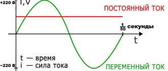
Electric current (DC or direct current), entering the armature windings (depending on their number for each in turn), creates an electromagnetic field in them, which has a south pole on one side and a north pole on the other.
Many people know that if you take any two magnets and place them with poles of the same name on each other, they will not come together, but if you place them with opposite poles, they will stick so that it is not always possible to separate them.
So, this electromagnetic field, which arises in any of the armature windings, interacting with each of the poles of the stator magnets, drives (rotates) the armature itself. Next, the current passes through the commutator and brushes to the next winding and so sequentially, moving from one armature winding to another, the electric motor shaft rotates together with the armature, but only as long as voltage is applied to it.
In a standard commutator motor, the armature has three poles (three windings) - this is done so that the motor does not “stick” in one position.
Three basic motor topologies
Three commonly used low-power DC motor configurations are brushed, brushless DC (BLDC), and stepper. Each operates through the interaction between currents in coils (or windings) and permanent magnets (in most designs), resulting in an attractive/repulsive magnetic field that causes rotation. All three types of motors have some similarities, but differ in the method of controlling the switching of current flowing through the rotor and stator windings.
They also differ in the ability to perform certain tasks, the quality of this execution and the flexibility of management.
- Historically, the first was the commutator type engine . As the rotor rotates, contact brushes, which are solid contacts typically made of graphite, touch corresponding areas on the rotor (Figure 1). As the rotor rotates, changing the brush contact points causes a change in the direction of current flow and therefore the magnetic field. The magnetic field interaction between the rotor and stator is then reversed, forcing the rotor to continue moving.
Rice.
1. Brushed DC Motor This mechanical circuit is conceptually simple. However, the disadvantage is that the brushes wear out and need to be replaced, the implementation of intelligent control is difficult because it is difficult to switch a given motor, and the brushes create electromagnetic interference (EMI), also known as radio frequency interference (RFI).
In its simplest form, a commutator motor does not need electronic control - it simply operates depending on the current and mechanical loads. In other embodiments, the motor power bus is turned on and off using a transistor circuit, which is the simplest control option. It is also possible to use a driver chip to improve performance and provide control over speed and torque.
- In a BLDC , mechanical commutation is replaced by electrical commutation using transistors. The most commonly used are MOSFETs, which are driven by a gate driver (some designs use insulated gate bipolar transistors - IGBTs). A separate controller controls the precise switching of the coil at the moment necessary to keep the motor spinning at the desired speed (Figure 2).
Rice. 2. Brushless DC motor
Note: BLDC motors are sometimes called electronically commutated (EC) motors, which is a more accurate description.
In BLDC, the rotor magnetic field is always present and is generated by permanent magnets. When current flows from one motor phase to another, the magnetic fields combine to generate a varying stator field.
The engine is controlled not only using electronics. Instead, switching can be configured in the gate driver with controlled rise and fall times to reduce EMI/RFI. The main problem is that softer shifting leads to a loss of power and a decrease in engine efficiency, and in this situation the designer needs to find the best possible compromise solution. Some newer shutter drivers use a variety of complex and subtle tricks to make this task easier.
- The stepper motor uses the BLDC motor concept, incorporating a large number of coils (or poles) located around the periphery of the motor (Figure 3). By alternately switching on and off these poles, pitch and rotation of the rotor in the forward or reverse direction are induced.
Rice. 3. Stepper motor
There can be 16 or 128 (or more) poles, depending on the required rotation accuracy, which is directly proportional to their number. Stepper motors are available in unipolar two-phase and bipolar two-, three-, and five-phase configurations. The most common of them is a bipolar two-phase motor.
In a stepper motor, the rotor magnetic field is generated by a permanent magnet, and the stator magnetic field is generated by a current flowing in a certain phase. As a result, the rotor will align itself with the stator's magnetic field to achieve the desired position.
A stepper motor is well suited for applications that require quick stop/start, positioning or back/forward movement, but is not suitable for long-term continuous operation. It is often used in printers and step positioning instruments (to name just two of its many uses). Although positioning accuracy depends on the number of poles, using an advanced method in which adjacent poles are partially switched on (called microstepping) allows for more precise control of switching and positioning.
Disadvantages of commutator motors
By themselves, commutator motors do a good job of their job, but this is only until the moment when the need arises to get the highest possible speed from them at the output. It's all about the same brushes mentioned above. Since they are always in close contact with the collector, as a result of high speeds, friction occurs at the point of their contact, which will subsequently cause rapid wear of both and subsequently lead to a loss of effective electric power. engine. This is the most significant disadvantage of such motors, which negates all its positive qualities.
Similarities and differences between motor control integrated circuits
The advantage of low-power motors, besides their modest current and voltage requirements, is that MOSFET gate drivers can be integrated with controllers and optimized for specific needs. Let's take a look at a trio of related offerings from STMicroelectronics . These three ICs from ST have many basic characteristics that allow them to be used in combination with different types of engines. In addition, they facilitate modeling and are easy to learn.
Here are some of the benefits these products have:
- Maximum integration using microcontroller interface (MCU), control logic, driver and MOSFET bridge (requires only a few passive components and no need for external active components);
- low operating voltage 1.8...10 V, which is well suited for low-voltage engines, especially those running on small batteries;
- High output current up to 1.3 A (RMS) and 2 A (peak) for each output;
- power consumption in standby mode up to 80 nA;
- Increased reliability with under-voltage lockout (UVLO), thermal and overcurrent protection;
- small QFN package measuring 3x3 mm.
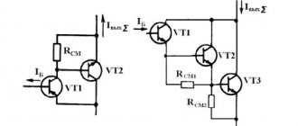
Let's look at the similarities and differences between these three motor control chips. STSPIN220, designed for stepper motors, combines control logic, high efficiency and low resistance drain-to-source RDS(ON) open channel (Figure 5). The controller implements current mode control using pulse width modulation (PWM) with programmable turn-off time. STSPIN220 supports a resolution of 256 microsteps per full step, which allows you to make movement as smooth as possible.
Rice. 5. STSPIN220 chip for controlling a stepper motor
Microcircuits similar to the STSPIN220 model:
- STSPIN230 – monolithic driver for three-phase BLDC motors;
- STSPIN240 – monolithic driver for two independent DC motors;
- STSPIN250 is a monolithic driver for one DC motor.
Note: The STSPIN250 driver is a single motor driver, unlike the STSPIN240 dual motor driver. STSPIN250 can provide higher current of 2.6A (rms) and 4A (peak).
All these integrated circuits have the most similar external interface and operational commands; only their interfaces on the motor side are functionally different.
Operating principle of a brushless motor
Here it’s the other way around; brushless motors lack both brushes and a commutator. The magnets in them are located strictly around the shaft and act as a rotor. Windings, which already have several magnetic poles, are placed around it. A so-called sensor (sensor) is installed on the rotor of brushless motors, which will monitor its position and transmit this information to the processor, which works in conjunction with a rotation speed controller (data exchange about the rotor position occurs more than 100 times per second). As a result, we get smoother operation of the motor itself with maximum efficiency.
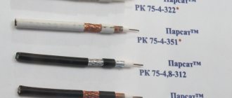
Brushless motors can be with or without a sensor. The absence of a sensor slightly reduces the efficiency of the motor, so their absence is unlikely to upset a beginner, but the price tag will pleasantly surprise you. It is easy to distinguish them from each other. Motors with a sensor, in addition to 3 thick power wires, also have an additional cable of thin ones that go to the speed controller. Both beginners and amateurs should not chase motors with a sensor, because only professionals will appreciate their potential, while others will simply overpay, and significantly.
Are you here
Home » Blog » Brushless or brushless motor of a radio-controlled model, choose the electric motor of a radio-controlled car or quadcopter.
Published: August 28, 2014
Hello everyone, today we will talk about the difference between brushed and brushless motors.
Before purchasing a radio-controlled model with electric drive, you need to decide on the choice of electric motor, which comes in two types: brushed and brushless motors .
The main difference for the consumer:
commutator motors are cheaper, but models with such motors develop lower speeds. Brushless motors are more expensive, but can reach higher speeds and are also more wear-resistant. Below is a little more detail:
Pros of brushless motors
Almost no wearing parts. Why “almost”, because the rotor shaft is mounted on bearings, which in turn tend to wear out, but their service life is extremely long, and their interchangeability is very simple. Such motors are very reliable and efficient. A rotor position control sensor is installed. On commutator motors, the operation of brushes is always accompanied by sparking, which subsequently causes interference in the operation of radio equipment. So, for collectorless ones, as you already understand, these problems are excluded. There is no friction, no overheating, which is also a significant advantage. Compared to commutator motors, they do not require additional maintenance during operation.
Bottom line
Drones are a rather complex and precise mechanism that requires a careful approach to the selection of components. I hope that after reading this article you understand a little more about the driving force of your aircraft.
And as always, a banal but very important parting word - think before you act. Even spending a lot of money on the best equipment does not guarantee that it will work well. Start from what you need. Read, learn, analyze.
If you have any questions, ask in the comments on the site. We will try to answer them. And most importantly, without which your copter will definitely not fly. Subscribe to our groups on social networks and share posts with friends (buttons for this can be found below). Good luck, pilot, see you again!
(
14 ratings, average: 3.86 out of 5)