To perform basic electrical work, it is absolutely not necessary to call a specialist. Knowing how to connect an LED switch, you can install it yourself. Agree, this skill will be especially useful if there are major repairs and updating of electrical wiring.
We will tell you about the connection diagram, installation method and difficulties that may arise during installation. You can also improve an ordinary switch with your own hands by making it backlit.
How a backlit switch works and works
We will describe the design of an LED switch using the example of a two-key backlit device.
The mechanism consists of the following elements:
- one input, two output terminals;
- current limiting resistor;
- moving contacts.
The design also includes a housing, a decorative panel and key pads.
Some models of backlit switches have a ready-made connected backlight mechanism. They also produce models in which the backlight conductors need to be connected to the terminals independently.
When the contacts of the LED switch open, the current flowing through the phase wire flows to the resistor, then to the LED or neon lamp. Next, the voltage passes through the lighting fixture and exits through zero.
Since the backlight is connected through a current-limiting resistor, the voltage in the network decreases and is enough for illumination, but not enough for the chandelier to operate.
This is how an LED switch works. If the lighting lamp burns out or is unscrewed, the circuit will be open and the backlight in the device will not work (+)
After the switch contacts close, the current, which always moves along the circuit with the least resistance, passes through the network that powers the lighting lamp - in this circuit the voltage is practically zero. The current also flows to the backlight circuit, but it is so small that it is not enough even to operate a neon lamp.
The circuit includes a current-limiting resistor and an LED or neon lamp. Otherwise, the design and connection method are the same as for a conventional device (+)
How to get rid of “blinking” lamps and possible problems
Installing a resistor in the cartridge
The main problem that owners of switches with indicators face is the flickering of the lamps and the indicator itself. Most of all, this phenomenon causes discomfort in bedrooms and the office. Improper operation will negatively affect the operating life of the switch itself and the lamp. You can get rid of the problem in the following ways:
- Give preference to LED lamps that are compatible with indicators in switches. Such lighting devices are already equipped with a soft start and a resistor. The device connects within a few seconds, so there is no flickering when the capacitor discharges. The main disadvantage is the high cost of such lamps.
- Connecting a shunt resistor in parallel will help get rid of the problem. It has no direct effect on the operating mode, but a small current will still flow through the resistor. Its power should be 2 W, and its resistance should be 50 kOhm.
- You can also connect an ordinary incandescent lamp with an energy-saving variety. In this case, the current flowing through the indicator circuit will pass through the filament. The disadvantage of this method is the large amount of electricity consumed.
- Incorrect operation may be caused by incorrect installation. For example, a mistake may result in the switch cutting off zero and not phase. This can cause not only incorrect operation, but also a short circuit. To solve the problem, just connect the switch correctly or call electricians.
Application of LED Switch
A backlit switch is installed where it is dark even during the daytime, and constant use of the lighting device is impractical. It is also used in rooms where access is required at night.
A switch with LED backlight, just like a regular one, can be solid-body or consist of one, two or more keys
The more light sources, the more keys on the switch will be required. To control lighting consisting of more than three lighting fixtures, dial switches are used, which are installed in one row.
To control lighting from several places, purchase a special backlit switch.
Electrical equipment, light, lighting
In the evening, returning home after work, the first thing you have to do is feel for the switch in a dark room. It’s even worse when you have to get out of bed at night in complete darkness and, half asleep, fumble along the wall to find the switch. Although this is unpleasant, many have already gotten used to it, instead of installing an illuminated switch at home.
Table of contents:
- Types of switches
- Advantages of an illuminated switch
- About the operating features of circuits for a backlit switch
- Pass-through switch with backlight
- Diagram of operation of an LED switch with resistance
- Features of the installation diagram of a switch on an LED with a capacitor
- Installation of a backlit switch
- Step-by-step instructions for installing a neon light bulb without a base with short leads into a switch
Types of switches
On the modern construction market, switches are presented in a sufficient assortment to choose exactly the type that will best suit the local lighting needs of the room. They differ both in appearance and in design features - photo backlit switches.
Main types of switches:
- keyboards;
- push-button;
- sensory;
- rotary;
- corded
In a residential area, a walk-through switch with backlight and all of the listed varieties can also be used, but the most widespread are:
1. Single-key switch with backlight - applicable for closing only one circuit, sold with a built-in diode for night illumination.
2. Two-key switch with backlight - has 2 switches and is used for chandeliers and other multi-lamp fixtures. The connection to the network is designed in such a way that one key can simultaneously turn on 1-2 or more light bulbs, and when the second key is turned on, the rest of the chandelier lights up. Often a two-button switch is used to use a separate bathroom.
3. Three-key or four-key switches - capable of simultaneously closing 3-4 electrical circuits, so they are used to control lighting fixtures in several rooms from one place. For example, for convenience, in one place in the house there is a staircase, a separate bathroom and a hallway. It is most advisable to provide such a switch with backlighting if it is missing.
4. Cord switch - used in sconces and portable lamps; backlighting is usually not used.
Key switches are the most popular, and they are found in almost every apartment or house, in schools and kindergartens, in offices and other public places. Many modern models are sold with a backlight diode and a transparent shield so as not to stain the wall around the switch with your fingers. The touch-sensitive backlight switch is used less often.
Advantages of an illuminated switch
1. The general design and construction of backlit switches is almost the same as conventional models, but a small LED provides a significant advantage when used in a dark room.
How to choose an LED switch
When buying an LED switch, there is no need to chase expensive ceramic devices, since the power consumption of lighting devices is generally not very large.
For domestic use, it will be sufficient to use a high-quality plastic LED switch with a reliable contact group. The service life of such devices is about 40,000 switchings.
For hotel rooms, illuminated switches are used, which are controlled using a key card. They can be with or without a shutdown time delay
The choice is also made based on the design of the device, the type of inclusion - they produce keyboard and rotary, push-button, touch and cord.
Depending on the installation method, internal and external devices are distinguished. The case material can also be different - plastic, glass, copper, stainless steel are used, and slate, gold plated and even leather are used as decorative coatings.
But what you really need to pay attention to is the protection class (IP) - it indicates the possibility of using the equipment in certain conditions.
For example:
- An IP class of 20 indicates that the device is poorly protected from dust and moisture. Such equipment is used in residential premises.
- Class IP 45 and higher is used for marking switches suitable for connection in rooms with high humidity - baths, saunas, kitchens, toilets, etc.
- An IP class of 65 means that the switch can be used outdoors. Such electrical equipment has increased protection from dust and moisture. Installed outside the building - under the porch, canopy, on covered verandas. It has more massive keys, and at the point where the electrical wire enters there is a rubber seal.
The higher the class, the more protected the device is from external factors. This applies not only to switches, but also to sockets, toggle switches, and other electrical equipment.
Connection diagram for lighting switches from two places
Conventional switches installed in rooms ensure that the light is turned on or off from only one place.
However, situations often arise when it would be more convenient and comfortable to control the light from different points in an apartment or house. This is especially true for flights of stairs and long corridors where there is no natural light. That is, at the beginning of climbing the stairs, the light is turned on by the first switch, and at the end it is turned off by the second. This problem is successfully solved by connecting lighting in an apartment with two light switches. This ensures not only ease of use of lighting devices, but also significant energy savings. To install the switches, you must first lay a three-core cable to the connection point, purchase two pass-through switches and a junction box.
When using the simplest circuit, the neutral wire passes from the panel to the distribution box, in which it is connected to the neutral conductor connected to the lamp. The switches themselves are connected through the box using a three-core cable. To supply the phase to the switches and then to the lamp, a single-core wire is used. When connecting three or more light switches, the number of wires in the cable increases accordingly to four, five, etc. Thus, installing a double pass-through switch is not particularly difficult. You just need to carefully observe and control the sequence of connecting the conductors.
The effectiveness of light control can be assessed using the example of a long dark corridor illuminated by two lamps. At the very beginning of movement along this corridor, the light is turned on by the first pass-through switch. Once the person is in the right place, for example, near the kitchen or bedroom, the lighting is turned off by a second switch. That is, to turn off the light you do not need to go to the switch at the beginning of the corridor and then go back.
As another example, consider a bedroom in which the light control is also carried out by pass-through switches. In this room, the first switch is installed in the traditional place near the door, and the other - near the bed. Thus, in order to turn off the light you do not need to get up and go to the door.
How to carry out installation correctly
The illuminated switch mechanism involves a small lamp that glows when the switch is turned off. A small neon lamp or LED along with a resistance element can be used to illuminate the device. The backlight has wires that need to be connected to power during installation.
Preparing for installation and mandatory safety precautions
Without basic knowledge of safety precautions, it is better not to start working with electrical equipment at all. Illiterate electrical installation can lead to electric shock, failure of electrical appliances, and fire.
Basic rules of behavior when working with electricity:
- all work must be carried out in a de-energized network;
- it is unacceptable to overload the power grid;
- check the markings of the wires for compliance with the connected network;
- It is better to replace a damaged section of the network rather than repair it;
- Do not touch connected equipment with wet hands.
A regular indicator screwdriver or multimeter will help determine the nature of the conductors - where is the zero and where is the phase. The indicator is sufficient if the electrical network is single-phase. To analyze a three-phase network, use a multimeter.
Bringing one of the multimeter tentacles to the phase, the other is fixed on any of the conductors. The range for alternating current is set to 220 W. Zero upon contact will show a value of about 220 W, grounding is always lower
Installation example of a 2-gang switch with backlight
The main design differences between LED switches are in the backlight mechanism. It can be ready to use and does not require any action to connect it. Another type of design requires connecting wires that power an LED or neon lamp.
Let's consider a more complex option - how to connect a backlit device, in which the conductors need to be connected independently.
A design feature that allows easy access to the backlight wires can be useful if you need to turn it off
First of all, pry up the keys with a screwdriver or other suitable tool and remove them. Separate the core (internal mechanism) from the body.
Next, determine the correct position of the switch using an indicator. To do this, by touching the contacts with a screwdriver on one side and an indicator on the other, check whether the device is on or off.
If the indicator lights up, it means it is turned on. In this state, turn it so that the keys with the pressed side are located on top.
For a regular indicator screwdriver to work, you need to hold it correctly - the metal part must touch the contact plate, and the top must be touched with your thumb
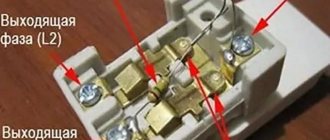
One of the wires coming from the indicator is connected to the input terminal, and the second is connected to the key contact. If there are several keys, then the wire is connected to the first of them, starting from the left. Simultaneously with the wire going from the indicator to the input terminal, the phase conductor is also connected.
The two outlet phase wires that go to the chandelier are connected to the output terminals simultaneously with the second backlight wire, making sure that it does not fall out of contact.
With this connection method, the backlight will turn on after opening the contacts using the first key. The second will not have any effect on turning off the backlight, and the light will remain on even when the lighting is on.
In order for the indicator light to go out when you press any of the keys, you need to make a jumper yourself that will connect the indicator to both keys.
If you do not take into account the connection of the backlight, installation proceeds as in a conventional device. A phase conductor is led through the junction box to the switch and connected to the input terminal L, inserting it into the hole and screwing it in with a screw.
Next, two outlet phase wires are connected to the device contacts L1 and L2, which also lead to the chandelier through the junction box. One of them is connected to one lamp, the other to the other two. The zero passes through the junction box in the wiring box, then goes to all the chandelier lamps, closing the contact.
As a result of correct connection, the first key will turn on one lamp, the second two, and two turned on keys will lead to the activation of the entire lighting device. When switched off, the LED (+) should light up.
Connection rules
Regardless of the type, installing an illuminated switch is the same. The differences are only in a couple of nuances.
Where to put the wires
Before you begin installing a switch with an indicator, it is important to understand the design. To do this, it is recommended to remove the keys. Most often they are fixed to the body using pins or a latch.
Under the keys you can see terminals for connecting wires. They almost always visually appear as small copper pads with screws.
To connect the wires, their end must be removed from the insulating layer and the wire must be stripped, passed under the screw and contact plate, and secured securely using the first. You should tighten it with force, but the main thing is not to overdo it, the structure is quite fragile. After a while, it is better to check the quality of the connection again and tighten it again, since the copper gives in slightly under the screw.
Connecting a light switch with one backlit key
Diagram for connecting the backlight to the network
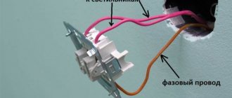
The connection diagram is extremely simple - zero is supplied directly from the panel to the lamp, and a phase is supplied to one of the switch terminals. From the second terminal the wire is fed to the output of the lighting fixture.
Implementing this scheme is simple and quick. The number of terminals depends on the number of keys in the switch. The single design has only 2 terminals, and the socket box must be equipped with two wires. It is simply impossible to get confused. You need to run one wire under the terminal from the panel, and the second from the lighting fixture. Where and what does not matter.
How to connect a switch with two keys and backlight
Connection diagram for a double model with backlight
The connection diagram of this electrical structure is not much different from the previous one. A three-wire wire is brought out into the socket box. Two wires are intended for a group of lighting devices, and one for power supply. This is where all the differences end.
In implementation, the method is a little more complicated, since you need to find a phase conductor and connect it to the required socket. The double switch is equipped with three contacts for connection. The phase is most often displayed in brown or red, and the color of the wires from the lighting device may be the same. Before connecting, the presence of phase voltage is checked, and if necessary, the wire is marked.
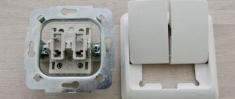
Installation of a single switch
Before you begin installation work, you must turn off the power to the room.
Then the old switch is dismantled, if it was previously installed. For this:
- We remove the keys by prying them off with a flat-head screwdriver.
Each key (if there are several of them) is carefully pryed off with a screwdriver and removed from the socket
- Carefully remove the decorative frame.
- We unscrew the screws securing the switch to the socket box and pull out the device body from the wall.
After unscrewing the two screws, the switch body can be freely removed from the socket socket
- We loosen the fastenings of the wires and disconnect them.
To disconnect the wires, just loosen the mounting bolts 1–2 turns.
As a result, we will have in our hands the inside of the old switch, which can be disposed of or kept for spare parts.
To properly install a new switch, you need to follow the same diagram as when removing it, only in reverse order, that is:
- Insert the inner part into the socket, having previously connected the wires to it.
- Tighten the bolts securing the socket box.
- Install frame and keys.
- Turn on the switch and check the operation of the device in all modes.
When the light is off, the backlight should be on
It should be noted that the process of connecting an illuminated switch is no different from connecting a conventional device.
Installation and connection of switches with several keys
Switches with several keys are often used in everyday life. With their help, you can control the operation of several lines of lighting devices at once. They are installed in large rooms or, if necessary, turn the lights on and off in several rooms from one place.
The installation of such switches is completely similar to that described above, with the only difference being that one phase wire and several (according to the number of keys) wires from consumers will come from the wall. It is important to connect them in the correct order
Why do energy-saving lamps blink?
The LED switch is not compatible with energy-saving lamps. A device conflict manifests itself in a short-term flashing of the lamp when it is off or in the so-called smoldering mode, when the lamp does not turn off completely, but barely glows.
The service life of an LED or energy-saving lamp in the wrong mode is significantly reduced and ranges from one to two months
This happens because inside the fluorescent lamp there is an electronic converter (capacitor), which, gradually recharging from the current passing through the backlight lamp, flares up.
A similar phenomenon occurs with LED strip power supplies, which also have a capacitor and are powered by a small current coming from the backlit switch.
Manufacturers of energy-saving lamps indicate that the use of their products is not compatible with the use of LED switches and dimmers.
You can get around this limitation by controlling the operation of the lighting device using a relay. From the switch, the command first goes to the relay, which directly controls the lighting.
The relay is produced by many manufacturers of electrical goods: Schneider Electric , ABB , Siemens . You can place it under the chandelier cap, behind the cornice in which the LED strip is installed.
You can use another solution to the problem - disconnect the neon lamp or LED from the power supply. This can be done by disconnecting the backlight wires from the terminals. But then the LED switch will lose its advantages.
Let's consider solutions that still allow you to combine lighting and the use of energy-saving lamps.
New technologies: touch pass-through switches
Stylish touch switches are more expensive than regular ones, but they are in demand - they have become a natural part of modern “digital culture”. Touch devices are quite complex electronic devices. A high-power thyristor or transistor is used to switch the current, and the signal that opens (or locks) the device comes from a sensor - a sensor that responds to some external influence.
The sensor can be a motion sensor, or an acoustic one, or a capacitive one that responds to touch. Sensitive sensors react even before touching, just bring your hand to a distance of 1-3 centimeters. Homes usually install capacitive touch switches, or those combined with a motion sensor. All touch devices can be controlled remotely. If the control panel is not included, it must be purchased separately.
The semiconductor device responsible for turning the current on and off can also be used to control the current strength and light brightness if equipped with a dimmer
It is important to know that dimmers are not suitable for all lighting fixtures
The photo shows a touch switch.
Pass-through and cross touch switches, like mechanical ones, are used to control lighting fixtures from different points. Compared to mechanical ones, they are more functional: they can be controlled remotely and control the light intensity.
Externally, touch devices are a smooth glass panel; when connected, there is a visible indication on it: blue firefly - OFF, red - ON. To control the lighting device, you just need to touch the device panel.
The paradox is that technologically advanced sensor devices do an excellent job of controlling incandescent or gas-discharge lamps, but problems arise when turning on advanced LED lamps. In the “touch switch - LED lamp” circuit, when turned off, weak electrical impulses can be induced, due to which the LEDs “wink”. Sometimes there are problems with the dimmer if it regulates the current through the LEDs.
In this case, it is recommended to install an additional adapter... or simple mechanical switches through which no pulses pass.
The figure shows a diagram of connecting the adapter in parallel with the LED lamp.
In this picture, the adapter is connected to the junction box and affects all LEDs included in this circuit.
Let's look at the connection diagrams for pass-through touch switches.
This shows the connection of two touch pass-through switches.
Shown here is the connection of three pass-through touch switches.
Note that in the middle there is the same touch switch as at the edges. That is, touch devices are not divided into “simple” and “cross”.
In the chain of touch switches there is a “main” one - which is shown on the left; three wires go to it (one wire is from the load). Before starting work, the system must be synchronized. Touch the panel of the main device and wait for a beep for 5 seconds. After this, you need to touch the second switch. Synchronization completed. Next, the third, fourth, and so on are synchronized with the main switch.
DIY illuminated switch
During the operation of electrical equipment, it sometimes turns out that in some of the rooms it would be nice to have a backlit switch. To do this, you don’t have to buy a device - you can improve your old one yourself.
What you will need for this:
- regular switch;
- LED with any characteristics;
- 470 kOhm resistor;
- diode 0.25 W;
- the wire;
- soldering iron;
- drill.
Using a soldering iron, they begin to assemble the circuit. The cathode of the diode (marked with a black stripe) is connected to the anode of the LED (the anode has a longer leg). The resistor is soldered to the positive terminal of the LED and to the wire that will serve as the connection to the switch. The second wire is connected to the cathode of the LED.
If you do not have a resistor of suitable power at hand or there is not enough space for placement, then it can be replaced with two resistors of lower power by connecting them in series (+)
Next, connect everything to the on-off mechanism. The phase conductor that leads to the lamp is connected to the terminal along with one of the wires leading to the LED. Another wire is connected to the input terminal along with the phase wire, which supplies current from the mains.
It is necessary to carefully insulate the exposed sections of the wire and prevent the conductors from touching the housing; this is especially important to do if it is metal.
Check the connection diagram of the backlit switch for functionality as follows: the key, closing the contact, causes the chandelier or lamp to light up; when it is off, the LED lamp lights up. If the circuit works correctly, you can install the device in the housing.
To make the lighting visible, place the LED lamp into a drilled hole at the top of the housing. This is not necessary if the body is light - the light will break through it.
The switch can be illuminated using a neon lamp. The circuit uses a HG1 gas-discharge lamp and any type of resistance with a nominal value of 0.5-1.0 MOhm with a power of more than 0.25 W (+)
Switch illumination circuit for a neon light bulb (neon)
The backlighting circuit for a switch on a neon light bulb (neon) is devoid of the disadvantages inherent in the LED backlighting circuits presented above. This switch illumination scheme is suitable for chandelier switches and any other types of lamps, with both incandescent light bulbs and energy-saving fluorescent and LED lamps installed in them.
When the switch is open, current flows through resistance R1, the discharge lamp HG1 and it lights up. R1 of any type with a power of more than 0.25 W, rated from 0.5 to 1.0 MOhm.
In the photo you see the assembled switch illumination circuit, which couldn’t be simpler. It is enough to connect a resistor in series with a neon light bulb of any type and the circuit is ready.
Switch with on indicator
Switches with indicators differ from LED switches in a completely different principle of use - the lamp in them lights up when the lighting is turned on. The main purpose of a pilot light is to signal that lights are on in a basement, attic, storage room or outdoors.
Used to control energy consumption. The indicator can be set for each of the keys or only for one of them.
The connection and operation diagram of a switch with a backlight function is built according to the following principle. The test lamp is connected in parallel to the switch terminals. When the circuit is completed, current flows through the indicator and the light fixture - both light up. If the switch is off, no current flows to either the indicator or the lamp.
Indication of switched-on lighting can be done in combination: 1 indicator lamp per key or one lamp for each key (+)
Possible problems
If you follow the rules and do everything according to the instructions, there will be no problems. The problem can only arise if you buy a “semi-finished product” . In it, the light bulb lies next to the switch in the package. But it’s hard to call it a problem. Rather, at the moment it is a small obstacle. In this case, you need to connect the two wires of the light bulb to different wires of the socket box.
If the switch is single-key. When connecting a two-key device, the indicator lamps are connected by one wire, and the others are connected to different phases. It doesn't matter which ones.
A switch with an LED differs from a regular switch only in the light bulb . No need to worry about spooled kilowatts. The backlight consumes a tiny fraction of electricity. Only works when the lights are off.