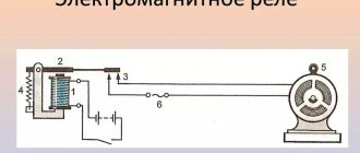
It is impossible to imagine the life of a modern person without electrical energy; this applies to all areas of our life - from work in production and at home to personal worries and time spent during leisure hours. Everyone knows that during the operation of electrical networks and power equipment there are emergency situations from which devices are used to protect, because There are automatic switches or fuses in every apartment or country house. But few people know that voltage surges in electrical networks are also dangerous for household appliances and other equipment. To prevent such unpleasant situations, 220 V voltage relays for the home are used, and they will be discussed in this review.
Voltage control relays come in different designs and differ in the type of installation, connection diagram and settings parameters
Why do you need a voltage control relay?
Household electrical appliances are designed for a voltage of 220-240 V. From time to time, emergency situations arise in the electrical network. The voltage in the outlet jumps up or down. Jumps can disrupt the operation of household appliances or completely destroy them.
Voltage drops in the network
A common case of voltage drops is a zero break. In this case, in one phase the voltage drops below the permissible level. On the other, on the contrary, there is a significant increase in voltage up to 380V.
Another situation is typical for old houses with poor electrical wiring and loose contacts. Due to the poor condition of the cables and their overload, the voltage in the sockets can drop to 170 V or lower. This is dangerous for electric motors of washing machines and refrigerators.
A voltage control relay protects electrical appliances. This small device is located in the distribution panel of the apartment. It has a compact design, is conveniently mounted on a DIN rail and performs its task completely autonomously.
Additional Information. It is necessary to distinguish voltage control relays from all kinds of stabilizers and UZMs. All of the listed devices are used to protect household appliances. The stabilizer is an active device. He is able to independently adjust the voltage in the apartment. The RN performs a simpler and more passive function. It simply turns off the consumer when the permissible threshold is exceeded and, in itself, does not affect the voltage in any way.
If there is not enough power
There are often situations when it is necessary to install protective relays on powerful equipment, but the protective unit itself is not suitable according to the technical data. There is a way to increase the rated current by installing an intermediate relay. The idea is very simple: the load is connected to the network through a powerful contactor, the coils of which, in turn, are connected through a protective unit. As a result, the main load does not go through the relay, which is not overloaded.
The connection is carried out in the following sequence:
- We attach the protection relay and the starter to the DIN rail next to each other.
- When the power is turned off, we connect the “phase” and “zero” relays to the power input.
- Using a wire of the required cross-section, we connect the “phase” to the input of the breaker contact of the starter.
- The output of this contact is to the load. We take “zero” directly from the line.
- We connect two wires to the starter coil. We connect one to the zero bus, the other to the output of the breaking contacts of the protection relay (at the bottom of the device body).
- We connect the input of the relay breaking contacts to the phase wire of the network.
Now it is possible to control loads significantly exceeding the rated value of the protective relay.
Purpose of buttons and pins
There are 3 contacts on the front panel of a standard voltage limit relay. They are designed for connecting neutral and phase conductors. Looking from left to right, the contacts have the following purposes:
- Common neutral wire. This contact is bifurcated into 2 points.
- Supply voltage input. The phase coming from the meter is connected to it.
- Exit to the apartment. This wire will turn off when there is a voltage surge or sag.
Pins 2 and 3 are normally open power contacts. If the voltage between 1 and 2 is within normal limits, then 2 and 3 are closed, and the phase can freely pass into the apartment network.
Voltage relay device
The voltage control relay has a simple operating principle. The internal controller continuously measures the network voltage. If it goes beyond the norm, then the electromagnetic relay turns off the apartment. The device is digital. It responds both to excessively high voltage and to low voltage.
Switch-on time delay
LV is characterized by a switch-on delay. If the voltage falls below the permissible norm, the device will turn off and break contacts 2 and 3. When the voltage returns to normal, the relay does not turn on. It waits for a while. For example, 15 seconds. This is necessary to avoid false activations of the LV. A control for setting this parameter is provided on the front panel of the device.
The relay body has buttons with a display. They allow you to configure the operating voltage range and response delay time. Detailed information about setting up the device is contained in the instruction manual.
Operating principle of protective devices
To protect against electrical impulses caused by lightning, a lightning arrester is installed together with an SPD. And you can protect the line from the flow of electrons, the parameters of which do not correspond to the operating characteristics of the network, using special sensors, as well as overvoltage relays.
It should be said that both the DPN and the relay differ in principle of operation and purpose from the stabilizer.
The task of these elements is to stop the supply of electricity if the value of the difference exceeds the maximum threshold specified in the technical data sheet of the protective device or set by the regulator.
After normalizing the parameters of the electrical line, the relay switches on automatically. DPS for line protection should be installed only in conjunction with a residual current device. Its task is to cause a current leak when a malfunction is detected, under the influence of which the RCD will trip.
Visually about the voltage relay in the video:
The disadvantage of this circuit is that it needs to be turned on manually after the voltage returns to normal. In this regard, a voltage stabilizer compares favorably. This device provides an adjustable time delay for current delivery if it is triggered by excessive voltage. The stabilizer is often used to connect air conditioners and refrigeration units.
Technical specifications
The main characteristics of the LV include operating voltage, number of connected phases and maximum throughput power. Below are the parameters of one of the popular relays - RV-32.
| Characteristic | Meaning |
| Supply voltage | 220 V |
| Maximum active power of the consumer | 7 kW |
| Load current limit | 32 A |
| Measurement error | +/-1 % |
| Degree of protection against dust and moisture | IP20 |
| Number of relay operating cycles | 100 thousand |
| Working temperature | from -5 to +40°C |
| Limit cross-section of connected wires | 6 sq. mm |
From the characteristics it follows that the relay is powered by a mains voltage of 220 V. The internal contacts are capable of continuously passing a current of 32 A, which corresponds to a consumer with a power of 7 kW. IP class 20 says the device is not suitable for use in wet areas or outdoors. It can be installed in a special electrical panel. 100 thousand operating cycles is the number of switching on and off of the relay that it can withstand without destruction.
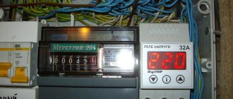
Voltage relay DigiTOP Vp-50A IP20
At what price to buy a 220 V voltage relay for the home - price review
220 V voltage relays for the home can be bought in stores and retail chains specializing in the sale of electrical equipment, as well as on the Internet, where a fairly wide selection of similar products is also available. Prices for the 220 V voltage relays discussed in this article for the home are shown in the following table, as of the second quarter of 2022, when sold through online resources.
| Image | Model | Average cost (as of May 2022), rub. |
| "ZUBR" (RBUZ) D16 | 1640 | |
| "ZUBR" (RBUZ) D25/D25t | 2000 | |
| "ZUBR" (RBUZ) D32/D32t | 2300 | |
| "ZUBR" (RBUZ) D40/D40t | 2600 | |
| "ZUBR" (RBUZ) D50/D50t | 2900 | |
| "ZUBR" (RBUZ) D63/D63t | 3200 | |
| "TDM ELECTRIC" RN-101M | 2620 | |
| "TDM ELECTRIC" RN-111M | 1800 | |
| "TDM ELECTRIC" RN-102 | 1600 | |
| "Meander" UZM-51M | 2620 | |
| "Meander" UZM-50M | 1800 | |
| "Meander" UZM-16 | 1600 | |
| "DigiTOP" Vp-16AS | 1900 | |
| "DigiTOP" MP-63A V-Protector | 5020 | |
| "DigiTOP" VA-32A VA-Protector | 2770 | |
| "DigiTOP" VA-63A VA-Protector | 3790 | |
| "ABB" CM-EFS.2S | 6463 |
The variety of offers on the electrical products market allows you to choose a model in accordance with the technical requirements for these devices in different price ranges.
Types of launch vehicles
Various types of devices need protection from voltage surges. Some of them operate on household voltage 220 V and consume minimal power. Examples of such devices include smartphone chargers or LED light bulbs. Others also operate on 220 V, but already consume thousands of watts of power, for example, electric kettles and irons. Still other devices require three-phase power supply of 380 V. A conventional single-pole LV is not suitable for them. Among such consumers are industrial machines and powerful asynchronous motors. Therefore, all relays for voltage control are usually divided by type of housing and type of load.
By case type
This classification indicates which devices and in what quantities can be connected to the relay. According to the type of execution, the launch vehicle is divided into 3 types:
- rosette;
- in the form of an extension;
- with installation on DIN rail.
The first type is the easiest to use. This surge protection relay plugs directly into an outlet. On one side of the case there is a corresponding connector in the form of a plug. On the other part of the device there is a standard socket for connecting the load. This type of LV can be quickly removed and connected to another location.
The second type is made in the form of an extension cord. On its surface there are several sockets for loading. Unlike type 1, this relay is equipped with a cable and plug. The device is convenient for stationary connection of office equipment.
The third type is the most professional. The pH is installed in the shield. It has an extended list of functions, high throughput, and at the same time protects all electrical appliances in the apartment.
By number of phases
Electrical consumers operating on alternating current are divided into 2 groups. The voltage control relay has a similar division. Namely:
- single-phase LV;
- three-phase.
Single-phase modification is suitable for home use. These relays are installed in apartments, garages and cottages. They pass through one phase and zero. That's why they are called single-phase.
The operating voltage for such LVs is 220V. Their contacts are designed for a current of 30-40 A, which corresponds to the maximum values for residential wiring. The device has a minimal list of settings and, if you read the instructions, is suitable for use by an ordinary person without specialized education.
Three-phase voltage monitoring relay ZUBR 3F
The second type of relay is more complicated. It controls voltage on 3 phases simultaneously. This modification is suitable for units consuming 380 V from a network. The relay has an expanded list of adjustments and requires minimal experience in setting up automation systems.
Varieties of RLVs according to other parameters
In addition to differences in the type of power supply, these devices differ in a number of characteristics that determine the method of their installation, and in functionality.
Type of execution and dimensions
In accordance with this feature, all RLV models produced by industry are divided into three types:
- plug-socket adapters;
- extension cords with several sockets (from one to six);
- compact switches mounted on a DIN rail in a panel.
The first two product options are used to protect individual electrical appliances or several consumers combined into groups. They connect to a regular power outlet. Devices of the third type are installed in an electrical panel in which other protection devices are mounted.
Adapter housings and extension cords are made quite convenient to use. Manufacturers try to reduce their dimensions as much as possible so that they do not spoil the interiors with their appearance.
Base and additional functions
Voltage relay device
According to the internal logic of operation and electronic filling, all known samples of ILVs are divided into microprocessor products and devices made on the basis of digital comparators. The first of them are somewhat more expensive, but they provide more accurate and smooth adjustment of the lower and upper response thresholds. Most of these protective devices are microprocessor based and stand out from other products due to the following features:
- the presence of two response thresholds (Umax and Umin);
- the use of built-in LEDs mounted in the device panel - they monitor the presence of voltage at the input and output;
- the use of a liquid crystal display, which displays the values of permissible deviation limits and effective voltage.
All these features significantly increase the functionality of the devices and simplify working with them when installed in an apartment or private house.
Common connection schemes
There are also differences in the power of consumers that are connected through the LV. One is enough to supply phase and zero. Others require three-phase power. For each load power category, a corresponding relay connection diagram is required. Therefore, it is customary to distinguish 3 ways to activate these protective devices:
- single-phase LV;
- three-phase;
- connection diagram via contactor.
Connecting a single-phase LV
The circuit is used to connect 220 V consumers. It is suitable for both an apartment and a separate device.
Initially there is a single-phase LV, supply and outlet lines. Installation of the circuit is carried out according to the plan below:
- The common neutral wire is connected. The corresponding terminal is on the relay. It is designated by the letter "N". Depending on the model of the device, there may be two zero terminals. In this case, the zero from the supply line is connected to one contact, and the outgoing line to the other.
- Then the phase wire of the outgoing line is connected. On the device body this terminal is marked “L2”, “output L” or “out L”.
- The third stage is connecting the phase wire of the supply line. Voltage is always present on it, regardless of whether the LV operates or not. In a standard electrical panel, this conductor comes from the output of the meter or automatic switch.
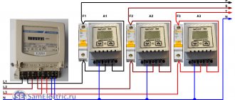
Diagram for three-phase voltage monitoring relay
Different models of three-phase voltage control relays have a different set of terminals for connecting wires. There are 8 of them as standard. Mains voltage terminals (4 pcs.) are needed to supply three controlled phases and zero to the device. On the device body they are designated L1, L2, L3 and N. Output relay terminals (4 pcs.) are used to connect subsequent protection and automation devices. They are marked “NO” for normally open contacts, and “NC” for normally closed contacts.
The connection diagram is assembled in 2 stages:
- The phase and neutral wires of the supply line are connected to the RN terminals. Here you need to pay attention to the maximum permissible current of the contacts. As a rule, if the consumer is three-phase, then it consumes high power. The relay must be rated for these values.
- Subsequent devices are connected to the relay output. For example, a contactor, various alarm devices or “failure” indicator lamps.
Note! Expensive three-phase LVs are capable of monitoring not only voltage, but also a number of other network parameters. For example, critical phase imbalance and the correctness of their alternation. These functions are important for the correct operation of asynchronous motors and thyristor converters.
Connecting loads over 100 kW using a contactor
Some electricity consumers draw hundreds of amperes from the network. No launch vehicle is capable of handling such powers. In this situation, a separate contactor is used. It must be connected to the output relay.
In this scheme, the RN simply monitors the state of the network and generates a low-current control signal for the contactor. Its retractor coil is connected in series with the output of the voltage control relay. The main load current flows directly through the contactor.
Important! The LV should not be placed near powerful sources of radio interference, such as transformers or cordless phones. The interference they emit can affect the relay's measuring circuit and lead to false alarms.
Voltage stabilizer in the panel: installation
It is recommended to install the stabilizer near the power panel in accordance with the following diagram.
The stabilizer (as well as the LV) should be integrated into the overall circuit directly after the meter. After all, these devices are also consumers, therefore, they cannot be installed in front of the meter.
Recommendations for selection
From the above it follows that there are many types of voltage control relays. The selection is carried out taking into account the specific situation in which the RN will have to work. The most significant criteria for choosing a voltage monitoring relay are:
- Single-phase or three-phase network. An option is practiced when instead of one three-phase relay, 3 single-phase ones are installed.
- Relay type. Plug-in, designed for 1-3 consumers. They can withstand current up to 16 A. Modifications for DIN rail are more powerful. Through them it is possible to connect the entire apartment. The current passed is 40-80 A.
- Permissible relay current. For an ordinary apartment, a device capable of passing 30-40 A is suitable. This current is greater than the cross-section of household wiring will allow, but it is better to take the LV with a power reserve of 1.5-2 times. This way the device will last much longer.
- If a relay is purchased to connect a single household appliance, then before purchasing you should find out what its current consumption is. In this situation, it is enough to make a reserve of 30-50%.
Additional Information. There are voltage monitoring relays equipped with a built-in ammeter. These devices allow you to monitor the current consumed by the apartment. They can be used to provide protection against short circuits or network overloads.
What is voltage fluctuation?
Voltage fluctuations are a common phenomenon that leads to electrical equipment burning out and damaging it. Organizations involved in the repair, maintenance and modernization of substations, transformers, and power lines are not in a hurry to change, improve, or achieve greater stability. It only gets worse every year.
The reasons for the appearance of unstable voltage are different. This is mainly due to equipment malfunction, damage to power lines and the use of “ancient welders” that overload the household network.
Normal voltage fluctuations are acceptable within the range of 170-240 V. When it is higher or lower, problems begin: power (current) increases, insulation begins to melt and burn, electrical equipment and household appliances that are not designed for such a load fail.
Against the backdrop of confusion and irresponsibility, emergency situations arise that provoke the emergence of causes for sudden power surges:
- The appearance of 380 V voltage in the socket as a result of a phase contacting the neutral wire (for example, during a gust of wind);
- When the neutral wire breaks or burns out at low load, the voltage tends to increase to 400 V;
- Distortion in network load, current is distributed unevenly;
- Welding work when connecting a transformer or rectifier to the electrical network.
It became possible to protect your household appliances thanks to the use of a voltage relay installed on the power input circuit.
Setting LV response thresholds
The overvoltage protection relay is configured after analyzing the current state of the electrical network and wiring . It is necessary to pay attention to factors such as:
- Voltage at the socket. It is 220 V only on the pages of textbooks. The actual voltage in the network can be in the range of 190-240 V. It makes no sense to configure the LV to turn off when it drops to 210 V, if the voltage in the outlet rarely rises above 200 V. This is especially true for rural areas and in a private house.
- Power of household appliances. Some types of equipment consume high currents at the moment of startup, which sharply reduces the voltage in the network. This dip must be taken into account in order to select the lower protection threshold.
- At night the opposite happens. People are sleeping. Most of the electrical appliances in the house are turned off. The voltage in the network can go off scale up to 230-240 V. This phenomenon is taken into account when choosing the upper response rating.
Installation and configuration of voltage relays
Causes and danger of power surges
When there is a voltage drop in electrical networks, its amplitude changes for a short period of time. After this, it is quickly restored with parameters close to the initial level.
Such an electric current impulse lasts literally for several milliseconds, and its occurrence is due to the following reasons:
- Lightning discharges. They cause voltage surges of up to several kilovolts, which no device can withstand. Such fluctuations often cause network outages and fires.
- Overvoltage caused by switching processes when high power consumers are connected or disconnected.
- The phenomenon of electrostatic induction when connecting electric welding, commutator motors and other similar equipment.
The danger of consequences from overvoltages is clearly reflected in the figure, where lightning and switching impulses differ significantly from the rated mains voltage. The insulating layer in most wires is designed to withstand significant differences and breakdowns usually do not occur. Often the pulse does not last long and the voltage, passing through the power supply and stabilizer, simply does not have time to rise to a critical level.
Sometimes the insulation layer of a 220 V network may not withstand the increasing voltage. As a result, a breakdown occurs, accompanied by the appearance of an electric arc. For the flow of electrons, a free path is formed in the form of microcracks, and gases filling the microscopic voids serve as a conductor. This process is accompanied by the release of a large amount of heat, under the influence of which the conductive channel expands even more. Due to the gradual increase in current, the operation of the automatic protective equipment is slightly delayed, and these few moments are enough to damage all the electrical wiring in a private house.
Particularly dangerous are high and low voltages that remain in this state for a long time. This mainly happens due to emergency situations that need to be eliminated in order for the current to return to normal. There are no other methods of normalization or any special devices that protect against this phenomenon.
Checking pH using a multimeter
Full tests can be carried out using special equipment in an electrical laboratory. However, the accuracy of the output voltage readings can be checked with a conventional multimeter. The device must be switched to the mode for measuring alternating voltage up to 700 V. This is indicated on the switch as “ACV 700”.
Then use a multimeter to determine the voltage at the output of the LV and compare this value with the readings on the display of the protective device. You need to understand that both devices have some measurement error. The readings should be approximately the same. A difference of 2-3 V is not a reason to panic. But if the differences are more significant, then there is a malfunction in the launch vehicle.
The use of LV will protect household electrical appliances from voltage surges. To do this, you will need to select the correct settings for its operation. Approximate values can be found in the device data sheet.
The voltage control relay is selected taking into account the number of supply phases and the maximum power of the consumer. It is advisable to purchase a protective device with a current reserve of 20-30%. If you need to control the current consumption, it is better to install a device with a built-in ammeter.
Which is better: relay or stabilizer
Voltage stabilizer WESTER STW1000NP
Some users use a standard voltage stabilizer in their home instead of a control relay. In some cases, such a decision is considered justified. However, several nuances have been noted that are taken into account when choosing a reliable method of protecting electrical appliances. First of all, you need to keep in mind that they perform similar functions and can turn off the load in an emergency. But there is still a difference in their work and is manifested in the following:
- stabilizers are characterized by an increased noise level and are much more expensive;
- they are more inertial, especially when monitoring sudden voltage changes;
- they do not provide the ability to adjust setting parameters;
- These devices take up significantly more space.
As the input signal decreases, the stabilizer begins to consume more current, which is explained by the need to maintain the output voltage at a constant level.
Characteristics
The main job of the monitoring relay is to constantly measure the effective voltage value. If the nominal value is exceeded or, conversely, it decreases below the established norm, the power contact of the device opens and the phase is disconnected. Thus, the external supply network is disconnected from the internal wiring.
All devices of this type are divided into single- and three-phase. In the first case, only one phase is switched off, and in the second case, all three phases are switched off simultaneously. If a three-phase connection is used in domestic conditions, for protection it is recommended to install single-phase monitoring relays, individually for each phase. In this case, voltage surges occurring in one phase will not cause shutdowns of other phases. The three-phase protective devices themselves usually monitor the voltage on electric motors and other similar consumers.
One of the most important characteristics of single-phase devices is the current load. It is this parameter that makes it clear what electrical power is allowed to pass through a particular device. The current load is primarily taken into account when choosing a particular device.
Possible rational solution to security problems
My own experience in developing the most cost-effective and, in my opinion, promising protection devices led to the following solution (which has been successfully tested in prototype models, is patentable, or is the subject of “know-how” - under an appropriate agreement with an interested Manufacturer).
To eliminate the shortcomings of stabilizers and voltage relays, it is advisable to implement a cutoff of the excessive voltage amplitude in the range of 250-290 Volts of the input voltage (the most likely excess) and an instantaneous cutoff at a higher voltage. This is possible by introducing an active ballast with a powerful Darlington transistor (or two simple ones) into the power circuit. To increase the permissible power of consumers, it is possible to install a miniature fan (12 V) with a simple power supply for chargers. In this case, the 12/5 Volt transition is achieved very simply - by switching an additional zener diode in the charger circuit. That is, the protection device acquires the additional function of a charger.
Implementation of ballast control according to the principle noted above (synchronous amplitude cutoff, including all pulses) does not require the use of any controllers. Moreover, in recent new work on the circuit, it was possible to get rid of the relay for turning on the amplitude stabilization mode and, accordingly, from the electrolytic capacitor (there are none at all), thanks to the development of an original constant current switch on a thyristor (with hysteresis), which turned out to be very successful in the circuit used protection devices (judging by the author’s experience and the search for analogues, it can be considered an invention).
In standby mode, the control board consumes less than 0.5 W (depending on voltage). For instantaneous cut-off (about 1 ms), the author also developed and successfully tested (for several years, in different devices) the design of a relay release based on a thermal breaker type VK-1-10, widely used in network filters-splitters. However, due to the synchronous amplitude cutoff at the level of 250 V, up to 280–290 V of the mains voltage, the likelihood of a larger overvoltage is significantly reduced, so it becomes rationally justified to use a simple fuse, which is simply burned out by a powerful thyristor (with some current limitation) for a sufficiently long time for this purpose, an overvoltage pulse (taking into account the duration of the half-wave decay of the mains voltage). It should also be taken into account that the current through the fuse (about 20–40 A) “raises” the network voltage (due to its resistance).
A look at industrial protection devices from a technical (engineering) point of view
Let us note, first of all, that all simple heating devices are not afraid of large voltage deviations from the norm (the deviation can be up to +/- 40 Volts). Therefore, it is inappropriate to turn them on after the stabilizer, unnecessarily loading it. A stabilizer is needed mainly for a refrigerator if the voltage drops to 180-190 Volts for a long time.
In all cases of resolving issues of stabilization or other protection, it is necessary to take into account that:
- Stabilizers have a so-called “no-load current” (no load), which is continuously added to the load current. Therefore, in many cases, especially when powering low-power electronic equipment, the total electricity consumption will be much higher (the stabilizer, as a rule, does not turn off or turn on with the load). All manufacturers indicate efficiency for rated load.
- Most stabilizers do not have surge protection devices in cases of lightning or in the event of a break in the neutral wire in the electrical network (or they have the simplest ones, with a factory setting). The response time of the protection, as a rule, is more than half a voltage cycle, which is too dangerous when the voltage surge exceeds 300 V. It must be taken into account that the voltage controlled by the stabilizer and causing certain switchings continues to increase at the input of the power supply of the TV or other consumer for the entire time the protection is activated ( load disconnection), and these surges (impulses) often have a steep front.
- According to their operating principle, stabilizers pass short (up to several milliseconds) overvoltage pulses, so the quality of the output voltage is determined by additional filtering, which may be insufficient for some electronic equipment.
- Voltage stabilization during a drop in the network is not required for modern electronic consumers; they have their own stabilization in this zone.
- Voltage relays installed in a panel or on a socket (as an adapter) have relay settings for disconnecting the load when the voltage increases or decreases above the set values (manually adjustable). That is, there is a very unpleasant and even harmful functional feature for the consumer. For all, usually expensive, equipment, it is strictly necessary not to allow the voltage to exceed 250 V. At the same time, in many electrical networks, especially in dacha and village networks, this excess is very likely. Thus, there are frequent shutdowns of the TV and all other consumers, which quickly becomes boring and leads to an increase in the setting to 260 V and higher if the user is technically illiterate. The risk of equipment damage increases sharply (one must also take into account the response delay, which is also manually adjusted and can be dangerously long). To reduce the psychological impact of frequent shutdowns, the developers made automatic restoration of the protection device with a certain (configurable) delay. But, in many cases (especially for a computer), this will not allow users to maintain peace of mind and especially the fruits of long work at the computer.
- The vast majority of protective devices in the form of splitters or adapters that are widely available for sale do not have the protection indicated on the bright packaging at all. Most often, they have only a low-power varistor, which begins to somehow dampen the voltage (according to its characteristics, in microseconds) after about 350 V. But, the same voltage will be simultaneously applied to the input elements of the power supply of any electronic equipment, with a high probability of their breakdown and burning!
Thus, the situation regarding solving problems of surge protection does not seem to be as favorable as on store shelves and on the websites of leading Manufacturers.