Good day to all! In the last article, I talked about the effect of alternating voltage on circuit elements (resistance, inductance and capacitance) and the effect of these elements on voltage, current and power. In this article I will talk about the series and parallel connection of circuit elements and the effect of alternating voltage and current on such circuits.
To assemble a radio-electronic device, you can pre-make a DIY KIT kit using the link.
Series connection of circuit elements at alternating voltage
Let's start with a series connection of resistance R, inductance L and capacitance C and consider the effect on it of alternating voltage with frequency ω.
Series connection of circuit elements.
In this circuit, the input alternating voltage U, in accordance with Kirchhoff’s second law, will be equal to the algebraic sum of the alternating voltages on the individual elements
where UR, UL, UC are the voltage across the circuit elements, resistance R, inductance L and capacitance C, respectively,
Im – amplitude value of alternating current.
A graphical representation of voltages and currents on series-connected circuit elements is presented below
Voltages and currents in series connection.
The final expression is a trigonometric form of Kirchhoff's second law for instantaneous stresses and can be rewritten as
where R is active resistance,
X – reactance.
The value of active resistance R is always only positive, and reactance X can take either a positive value X > 0, in which case it is inductive in nature , or a negative value X < 0, in which case the reactance is capacitive in nature .
voltage resonance occurs
In this case, the circuit resistance is represented only by the active load R, and therefore the phase shift between voltage and current will be zero.
When making calculations, we are interested not so much in the current and voltage on individual elements, but in the current and voltage of the entire circuit. To do this, we will continue to convert the voltage
where Z is the total resistance of the circuit,
ψ – phase difference between voltage and current.
Thus, the amplitude value of the voltage Um and the amplitude value of the current Im are related to each other by the following relation
where Um is the amplitude value of the alternating voltage,
Im – amplitude value of alternating current,
Z is the total resistance of the circuit.
AC electrical circuits
Alternating current has become much more widespread in industry and in everyday life than direct current, since the design of electric motors is simplified, and synchronous generators can be designed for significantly higher powers and higher voltages than direct current generators. Alternating current makes it easy to change the voltage using transformers, which is necessary when transmitting electricity over long distances.
The amplitude of an alternating current is the largest value, positive or negative, received by an alternating current.
A period is the time during which a complete oscillation of current occurs in a conductor.
The phase is the angle
or , standing under the sine sign. Phase characterizes the state of alternating current over time. At t=0 the phase is called initial.
Intermittent mode:
. This mode can also include sinusoidal: - amplitude; — initial phase; — angular speed of rotation of the generator rotor.
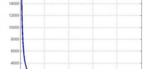
At f=50Hz T= 1/f=0.02 s,
314rad/s. The graph of a sine function is called a wave diagram.
Calculating AC circuits using instantaneous values of current, voltage and emf requires cumbersome computational work. Therefore, currents, voltages and emfs that change continuously over time are replaced by time-equivalent quantities.
When calculating electrical circuits, the sinusoidal function is expressed using Euler’s formula through exponential functions:
— rotary factor; — complex voltage amplitude; is the conjugate complex voltage amplitude.
Thus, a sinusoidal voltage can be represented on the complex plane by a rotating vector. Then the amplitude value of the voltage
will represent the magnitude or length of the voltage vector.
Parallel connection of circuit elements at alternating voltage
Now consider the parallel connection of circuit elements (resistance, inductance and capacitance) and the passage of alternating current through them.
Parallel connection of circuit elements.
Let us apply an alternating voltage U to the input of such a circuit, then the electric current in circuit I, in accordance with Kirchhoff’s first law, will be equal to the algebraic sum of the currents passing through the elements of the circuit
IR, IL, IC – currents in the circuit elements, resistance R, inductance L and capacitance C, respectively,
Um – amplitude value of alternating current.
A graphical representation of voltages and currents in parallel connected circuit elements is presented below
Voltage and currents in parallel connection.
Similar to Kirchhoff's second law, for the first law there is also a trigonometric form of notation that corresponds to the resulting expression. Let's perform another transformation of this expression
where g is active conductivity, b is reactive conductivity.
As can be seen from the formula, reactive conductivity can be positive b > 0, then it is inductive in nature, or it can be negative b < 0, then reactive conductivity is capacitive in nature. And active conductivity can only be positive.
A special case is the reactive conductance equal to zero, that is, in this case the conductivity of the inductance and capacitance are the same
This case is called current resonance , in this case the total conductivity will be determined only by active conductivity, and the phase shift between voltage and current in the circuit will be zero.
Let's determine the relationship between voltage and current in a parallel circuit
where y is admittance,
ψ – phase difference between voltage and current in the circuit.
Then the relationship between voltage and current in a circuit with elements connected in parallel will have the form
where Um is the amplitude value of the alternating voltage,
Im – amplitude value of alternating current,
y is the total conductivity of the circuit.
Electromagnetic processes occurring in electrical devices are usually quite complex. However, in many cases, their main characteristics can be described using such integral concepts as: voltage, current, electromotive force (EMF). With this approach, a set of electrical devices, consisting of appropriately connected sources and receivers of electrical energy, intended for the generation, transmission, distribution and conversion of electrical energy and (or) information, is considered as an electrical circuit
.
An electrical circuit consists of individual parts (objects) that perform specific functions and are called circuit elements
.
The main elements of the circuit are sources and receivers of electrical energy (signals). Electrical devices that produce electrical energy are called generators
or
sources of electrical energy
, and devices that consume it are called
receivers
(consumers) of electrical energy.
Each element of the circuit can have a certain number of terminals ( poles
), with the help of which it is connected to other elements.
There are two
and
multi-pole
elements. Double-terminal circuits have two terminals. These include energy sources (with the exception of controlled and multiphase), resistors, inductors, capacitors. Multi-pole elements are, for example, triodes, transformers, amplifiers, etc.
All elements of the electrical circuit can be divided into active
and
passive
.
An element that contains a source of electrical energy in its structure is called active. Passive elements include elements in which energy is dissipated (resistors) or accumulated (inductors and capacitors). The main characteristics of circuit elements include their current-voltage, Weber-ampere and coulomb-voltage characteristics, described by differential and/or algebraic equations. If the elements are described by linear differential or algebraic equations, then they are called linear
, otherwise they belong to the class of
nonlinear
.
Strictly speaking, all elements are nonlinear. The possibility of considering them as linear, which significantly simplifies the mathematical description and analysis of processes, is determined by the boundaries of change in the variables that characterize them and their frequencies. The coefficients connecting the variables, their derivatives and integrals in these equations are called the parameters
of the element.
If the parameters of an element are not functions of the spatial coordinates that determine its geometric dimensions, then it is called an element with lumped parameters
.
If an element is described by equations that include spatial variables, then it belongs to the class of elements with distributed parameters
. A classic example of the latter is the power transmission line (long line).
Circuits containing only linear elements are called linear. The presence of at least one nonlinear element in a circuit classifies it as nonlinear.
Let's consider the passive elements of the circuit, their main characteristics and parameters.
1. Resistive element (resistor)
A conventional graphical representation of the resistor is shown in Fig. 1, a. A resistor is a passive element characterized by resistive resistance. The latter is determined by the geometric dimensions of the body and the properties of the material: resistivity r (Ohm´ m) or the inverse value - conductivity (S/m).
In the simplest case of a conductor with length and cross-section S, its resistance is determined by the expression
.
In general, determining the resistance involves calculating the field in the conducting medium separating the two electrodes.
The main characteristic of a resistive element is the dependence (or), called the current-voltage characteristic (volt-ampere characteristic). If the dependence is a straight line passing through the origin of coordinates (see Fig. 1, b), then the resistor is called linear and is described by the relation
or
,
where is conductivity. In this case R=const.
A nonlinear resistive element, the current-voltage characteristic of which is nonlinear (Fig. 1, b), as will be shown in the block of lectures devoted to nonlinear circuits, is characterized by several parameters. In particular, the inertia-free resistor is matched with static and differential resistance.
2. Inductive element (inductor)
A conventional graphical representation of an inductor is shown in Fig. 2, a. A coil is a passive element characterized by inductance. To calculate the inductance of a coil, it is necessary to calculate the magnetic field created by it.
Inductance is determined by the ratio of the flux linkage to the current flowing through the turns of the coil,
.
In turn, the flux linkage is equal to the sum of the products of the flux passing through the turns and the number of these turns, where .
The main characteristic of an inductor is a relationship called the Weber-amp characteristic. For linear inductors, the dependence is a straight line passing through the origin of coordinates (see Fig. 2, b); wherein
.
The nonlinear properties of the inductor (see the curve in Fig. 2b) are determined by the presence of a core made of ferromagnetic material, for which the dependence of magnetic induction on field strength is nonlinear. Without taking into account the phenomenon of magnetic hysteresis, the nonlinear coil is characterized by static and differential inductance.
3. Capacitive element (capacitor)
A conventional graphical representation of the capacitor is shown in Fig. 3, a.
A capacitor is a passive element characterized by capacitance. To calculate the latter, it is necessary to calculate the electric field in the capacitor. Capacitance is determined by the ratio of the charge q on the capacitor plates to the voltage u between them
and depends on the geometry of the plates and the properties of the dielectric located between them. Most dielectrics used in practice are linear, i.e. they have a relative dielectric constant =const. In this case, the dependence is a straight line passing through the origin of coordinates (see Fig. 3,b) and
.
For nonlinear dielectrics (ferroelectrics), the dielectric constant is a function of the field strength, which causes the nonlinearity of the dependence (Fig. 3b). In this case, without taking into account the phenomenon of electrical hysteresis, the nonlinear capacitor is characterized by static and differential capacitances.
Equivalent circuits for electrical energy sources
The properties of an electrical energy source are described by the current-voltage characteristic, called the external characteristic of the source.
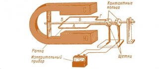
Further in this section, to simplify the analysis and mathematical description, constant voltage (current) sources will be considered. However, all the resulting laws, concepts and equivalent circuits fully apply to alternating current sources. The current-voltage characteristic of the source can be determined experimentally based on the diagram presented in Fig. 4, a. Here, the voltmeter V measures the voltage at terminals 1-2 of the source I, and the ammeter A measures the current I consumed from it, the value of which can be changed using a variable load resistor (rheostat) RN.
In the general case, the source’s current-voltage characteristic is nonlinear (curve 1 in Fig. 4b). It has two characteristic points that correspond to:
a – idle mode
;
b – short circuit mode
.
For most sources, short circuit mode (sometimes no-load) is unacceptable. Source currents and voltages can usually vary within certain limits, limited above by values corresponding to the rated mode
(a mode in which the manufacturer guarantees the best conditions for its operation in terms of efficiency and long service life). This makes it possible, in a number of cases, to simplify calculations, to approximate the nonlinear current-voltage characteristic in the working section mn (see Fig. 4, b) of a straight line, the position of which is determined by the working intervals of voltage and current changes. It should be noted that many sources (voltaic cells, batteries) have linear current-voltage characteristics.
Line 2 in Fig. 4b is described by the linear equation
| , | (1) |
where is the voltage at the source terminals with the load off (open key K in the circuit in Fig. 4a); — internal source resistance
.
Equation (1) allows you to create a sequential equivalent circuit
source (see Fig. 5,a).
In this diagram, the symbol E indicates an element called an ideal emf source
. The voltage at the terminals of this element does not depend on the source current; therefore, the current-voltage characteristic in Fig. 1 corresponds to it. 5 B. Based on (1) from such a source. Note that the directions of the EMF and voltage at the source terminals are opposite.
If the current-voltage characteristic of the source is linear, then to determine the parameters of its equivalent circuit
it is necessary to measure voltage and current for any two modes of its operation.
There is also a parallel source equivalent circuit. To describe it, we divide the left and right sides of relation (1) by . As a result we get
or
| , | (2) |
Where ; — internal conductivity of the source
.
Equation (2) corresponds to the source equivalent circuit in Fig. 6, a.
In this diagram, the symbol J denotes an element called an ideal current source
. The current in the branch with this element is equal to and does not depend on the voltage at the source terminals; therefore, the current-voltage characteristic in Fig. 1 corresponds to it. 6, b. On this basis, taking into account (2) from such a source, i.e. its internal resistance.
Note that in the design plan, if the condition is met, the sequential and parallel source equivalent circuits are equivalent. However, in terms of energy, they are different, since in idling mode for a series equivalent circuit the power is zero, but for a parallel circuit it is not.
the coordinated mode is important
operation at which the maximum power is consumed by the load RN from the source
| , | (3) |
The condition for this regime
| , | (4) |
In conclusion, we note that in accordance with the current-voltage characteristic in Fig. 5,b and 6,b ideal sources of EMF and current are sources of infinitely large power.
Literature
- Fundamentals
of circuit theory: Textbook. for universities / G.V. Zeveke, P.A. Ionkin, A.V. Netushil, S.V. Strakhov. –5th ed., revised. –M.: Energoatomizdat, 1989. -528 p. - Bessonov
L.A. Theoretical foundations of electrical engineering: Electric circuits. Textbook for students of electrical engineering, energy and instrument engineering specialties of universities. –7th ed., revised. and additional –M.: Higher. school, 1978. –528 p. - Theoretical
foundations of electrical engineering. Textbook for universities. In three volumes. Under general. ed. K.M.Polivanova. T.1. K.M.Polivanov. Linear electrical circuits with lumped constants. –M.: Energy, 1972. –240 p. - Kaplyansky A.E.
and others. Theoretical foundations of electrical engineering. Ed. 2nd. Textbook a manual for electrical engineering and energy majors at universities. –M.: Higher. school, 1972. –448 p.
Test questions and tasks
- Can the external characteristics of the source pass through the origin?
- Which mode (idle or short circuit) is an emergency for the current source?
- What are the equivalence and differences between series and parallel source equivalent circuits?
- Determine the inductance L and the energy of the magnetic field WM of the coil, if at a current in it I = 20 A, the flux linkage is y = 2 Wb.
Answer: L=0.1 H; WМ=40 J. - Determine the capacitance C and the energy of the electric field WE of the capacitor, if at a voltage on its plates U = 400 V, the charge of the capacitor is q = 0.2´ 10-3 C.
Answer: C=0.5 µF; WE=0.04 J. - For a DC generator, with a load current I1=50A, the voltage at the terminals is U1=210V, and the inflow equal to I2=100A, it drops to U2=190V.
- Determine the parameters of the source series equivalent circuit and the short circuit current.
Answer: - Derive relationships (3) and (4) and determine the maximum power supplied to the load according to the conditions of the previous problem.
Answer: