Advantages and disadvantages
The disadvantages of copper-based connecting combs include:
- the constant need to turn off the power when necessary to repair or service the device, which creates certain inconveniences;
- difficulties in implementing the modernization of the shield. If you need to install an auxiliary device, you will need to change the connecting comb or install an adapter jumper. But this may have a negative impact on the properties of the contacts;
- changing the first blown circuit breaker will require unfastening each contact on each device, but dismantling the bus may not work any other way;
- Due to the fact that different manufacturing companies in most cases can allow discrepancies in dimensions and instruction volumes, there is a need to install connecting busbars from only one manufacturing company together with the device that is planned to be connected. Choosing different companies may lead to the fact that the electrical connection will be impossible, because the pin may simply not reach the clamping contact;
- using homemade jumpers consisting of wire and electrical tape when connecting machines can be much cheaper than using a connecting bus. But this drawback applies to products from well-known brand manufacturers;
- using a connecting comb is pointless when connecting 1 or several machines. The reason for this is that it is designed for more than six modules.
One of the most popular combs on the Russian market are combs from ABB (abb or abb). This is a Swedish-Swiss company located in Zurich.
The advantages of copper-based connecting combs include:
- ease of use and high assembly speed;
- guarantees a high-quality and also safe galvanic connection, since the terminal can only clamp one contact (the exception is the first terminal, into which power is supplied from the line of the used pin bus, and the fork bus is free from this drawback).
- reduces the total number of contacts by 2 times, and due to this, the reliability of the resulting connections increases, eliminating the possibility of excessive heating of the contact points;
- An inherent advantage is the switching property; contact with a branch core is many times better than using a single-core cable as a jumper. Using a comb almost eliminates overheating of the contact pad;
- most often, the busbars of a connecting comb for six modules are designed for a load of 63 A. In order for the wire to withstand this load, it must have a cross-section of at least 16 square millimeters, and this significantly makes working with it more difficult;
- thanks to the comb in the shield, the number of wires is reduced, which affects the neatness of the wiring, as well as its indicativeness. This makes it easier to understand it if the need arises. The use of a comb allows you to independently carry out high-quality wiring.
Using a comb for automatic machines makes installation in the switchboard much easier and faster, and this fact is the main advantage.
How was the connection done before?
How to properly connect a fluorescent lamp
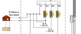
When performing assembly and installation work in switchboards, difficult situations often arise, especially when it comes to connecting protective devices and their groups of circuit breakers. To simplify and speed up this work, many different devices have been invented. Until relatively recently, when connecting many machines to a single line, it was necessary to create several jumpers from wire with insulation of the required cross-section.
Busbar for machines with jumpers made of insulated cable of the required cross-section
This method of connecting machines one to another has a very significant disadvantage - if the jumpers malfunction, the subsequent circuit breakers will not be provided with power. This problem can arise due to insufficiently well-made jumper contact and its subsequent burnout.
The disadvantages of connections made using homemade jumpers also include:
- significant time costs for installation associated with the need to measure the length of each cable section, stripping the insulation, and crimping the ends;
- unaesthetic appearance of the shield due to too many wires placed;
- interference for the installation of devices mounted on a DIN rail above the machines.
The occurrence of such situations can be eliminated using buses designed to connect several parallel connected RCD devices or circuit breakers.
Construction of connecting bars
Three-phase isolated fork bus
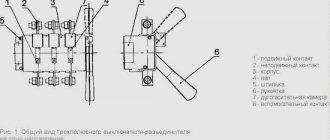
Unlike single-pole devices, where one phase contact is bridged, the design of the three-phase connecting bus provides four insulated combs with fixed pins. With their help, phase contacts are connected on 3- and 4-pole circuit breakers, as well as on residual current devices designed for 380 Volts. The fourth row is used to combine neutral terminals when disconnecting several group or linear RCDs.
When carrying out similar operations in 3-pole circuit breakers, where only the phases are connected, the contact taps of the fourth connecting row are simply bent.
When installing, instead of two protective devices, a 4-pole differential circuit breaker that completely replaces them, the comb taps are connected to all contacts involved in the circuit.
Known examples of three-phase bus connectors have designs that differ in the pitch between taps in each of the 4 rows (18 mm and 27 mm). The first of them is in demand when combining machines in a single-module design: the total number of occupied seats is 3 or 4. The second, rarer variety is selected with a body width of 1.5 modules: the occupied length is 4.5 or 6 seats. The design of copper connecting bars allows you to install a package of machines with a total number of pins from 12 to 60 pieces.
When getting acquainted with the design of a copper lath, it is also important to take into account its working cross-section, which, according to standards, must be at least 16 square meters. mm
Confirmation of the effectiveness of the use of these electrical products is an approximate calculation of the volume of conductors saved when using busbars.
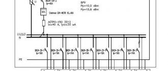
Schemes for connecting machines through a connecting comb
The comb bus for automatic machines is inserted into the connecting chain according to certain rules specified by the electrical circuit for its connection.
Since the connection of machines in 220 Volt networks is carried out only in phase (without zero), such a bus is usually called phase.
Depending on the type of power circuit into which the jumpers for the machines are included, they are designed to operate either in a single-phase line (220 Volts) or in a three-phase network. In the second case, the switching circuit is a triple copy of a single switching. The difference between the two options appears only in the design of the bus connector itself.
According to the PUE, the element is designed to create reliable contact between the upper (supply) terminals of automatic devices, the voltage from the output of which is supplied to the load line. To do this, the busbar must withstand significant currents, which determines the scheme for its inclusion in the general power circuits - all machines are connected with its help in parallel at the input. This rule is true for both single-phase (single-row) buses and three-phase combs for automatic machines. In the second case, the copper product has three insulated rows, offset by a step, corresponding to the distance between the phase terminals of a 380-volt switching device.
Tire for automatic machines (combs). Types and application. Peculiarities
During the assembly and installation of distribution boards, many difficult moments arise, especially when connecting groups of circuit breakers and protective devices. There are various devices that greatly simplify this work, for example a tire for automatic machines (comb). Until recently, to connect several electrical circuit breakers in a panel from one power line, the electrician had to make several jumpers from insulated wire of a given cross-section.
This method of connecting machines to each other has a serious drawback in that if one jumper fails, the circuit breakers following it will not receive electricity. This situation can occur as a result of poor-quality contact of the jumper and its burnout.
Also, the disadvantages of connecting with homemade jumpers include:
- A significant increase in installation time, since it is necessary to measure pieces of wires along the length, bend them, remove insulation, and crimp the ends.
- Violation of the aesthetics of appearance in the distribution board due to the large number of wires.
- Wire jumpers often interfere with the installation of devices that should be located above the machines on the DIN rail.
This situation can be eliminated by a circuit breaker bus, which is specially designed to connect a group of parallel devices in the form of residual current devices or circuit breakers. It is often called a comb or comb busbar because of its appearance.
Design features and types
A single-pole bus for automatic machines has a simple device consisting of a copper bus (a) and an insulator (b).
Depending on the type of connected devices, combs are divided into the following types:
The number of plates in the comb bus corresponds to the number of poles. Each type of connecting busbar is used for its own purposes. For example, single-pole connectors are used to connect 1-phase machines, and 4-pole connectors are used for 3-phase devices with four poles (3 phases + zero).
There are combs with different pitches: 18 mm and 27 mm. With smaller pitches they are used to connect single-module machines. The width of one module is 18 mm. Combs with a pitch of 27 mm are designed for connecting circuit breakers of 1.5 modules (18 x 1.5 = 27 mm).
Installation
Installation of a conventional comb bus takes place within the boundaries of the input or distribution panels. Usually this process does not raise any questions.
Features of connecting the bus under the comb:
- during installation, the conductive portion of the comb comes between the lower pressure plate and the comb itself, which is why the plastic insulating stage on it is directed towards the screw-shaped fastening;
- if this requirement is violated, it will not be possible to obtain an aesthetic connection that will not bend the plate;
- when installing a three-phase type comb, it is necessary to monitor the accuracy of the position of the insulators in order to eliminate the possibility of an interphase short circuit;
- When installing connecting busbars for automatic machines instead of typical cable jumpers, it is important to adhere to the generally accepted markings, which are located on the housings of the mounted products, and also meet the conditions of the existing standards.
Alignment methods
Comb
To correctly connect the machines, it is good to use a bus or comb, which is selected depending on the number of phases:
- for a single-phase circuit, a two-pole as well as a single-pole model is suitable;
- three-phase - four and three-pole.
Installation is easy. For the required number of machines, a specific comb model with the required number of poles is selected.
When choosing a comb with the maximum number of contacts, you should remove the excess using a hacksaw. To complete the installation, the tire is inserted into each clamp at the same time, and then the screws are tightened. The outputs are installed according to the diagrams.
Jumpers
Connecting machines using jumpers is used when there are a small number of switches and there is enough space in the panel for unhindered access to all contacts. This method can be used not only for a single-phase type of circuit, but also for a three-phase version.
For work carried out in the panel, it is worth preparing all jumpers of the required length, as well as the appropriate cross-section. For the so-called single-core conductors used, a cross-section is selected to combine the wires of the machines with a pre-calculated power. One of the suitable methods for creating jumpers is the continuous method.
At the end of such preparation, it is preferable to remove the existing insulation from the ends by about a centimeter, then expose the wire by removing the film with a knife.
Then you should install the ends into the entrance holes, while tightening the screws. Then the load sources are connected to the output, as in the photo, which clearly shows the connection of automatic switches.
Do not forget that it is important to not press the neutral and phase wires tightly because of their possibility of heating during operation of the electrical network, as well as the likelihood of unwanted alignment of the zero with the phase due to softening of the insulation under the influence of heating.
To combine switches with a cable, you can use a stranded wire with the required cross-section
However, in this case it is important to clean it a few centimeters.
A special tip corresponding in size to the cross-section of the wire used should be put on the end, crimped using pliers. You can combine switches in sequential order.
Following the instructions for combining switches located in the panel, but in the absence of the required tools, as well as tips, you can tin the uninsulated wire using a soldering iron.
In the absence of a special soldering iron, installation can be carried out using conductors without insulation. Such an installation is not practical and, under excessive loads, can cause overheating of the conductors in the overlap area and, naturally, a high degree of danger of unwanted fire. This type of association does not have an attractive appearance.
Remember that the correct connection of machines with each other using a stranded conductor should be carried out by adhering to a previously developed diagram. In this case, you can use machines from different manufacturers. Their diameters can be completely different, since installation with a flexible type wire makes it possible to do this.
When deciding which wire is preferable to connect the machines, check the correctness of this connection. As a rule, this is common for a three-phase circuit. Even a tiny mistake can cause a short circuit and, consequently, damage to the electrical device you are using.
How to install the comb correctly
The algorithm of actions is quite simple:
- If there are fewer plug-in modules than there are taps on the purchased comb, you need to cut off the excess part. This can be done using a regular hacksaw. It is better to cut the busbar and insulator separately, since the latter should be about one or two centimeters longer. This will prevent short circuits. For the same purpose, end caps are recommended if they are included in the kit. Otherwise, we use everyone's favorite blue electrical tape.
- The connection process itself is also not difficult. For fastening, the comb is inserted on top of the devices, and each tap must fall into the corresponding contact pad, after which the screws are tightened.
- The power input is connected to the far right or left (depending on the wiring) contact pad.
After this, we connect the wires leading to electricity consumers. At the final stage, all that remains is to connect the power (this work is performed by employees of the electric company) and the distribution box (panel) is ready for use.
To summarize, using a comb for circuit breakers greatly simplifies installation.
Which connecting bus is best to choose for your home?
It is difficult to imagine any modern electrical panel without a connecting bus. Thanks to it, you can compactly and simply place various modular devices in the distribution panel. We no longer have to get confused in bundles of wires; with the bus it is much easier to install wires and, if necessary, make wiring repairs.
However, if you set a goal to properly organize the contents of the distribution board, you should purchase a connecting busbar adapted to your electrical network
When choosing this equipment, pay attention to the following parameters:
Number of phases - a 1-phase connecting bus allows you to “process” only single-phase electrical networks. It is not difficult to guess that with such equipment our capabilities are greatly limited. Therefore, if you plan to efficiently transfer power to devices operating in three phases, you will need an appropriate three-phase switching bus. Pay special attention to this parameter, because a possible mistake in choosing a bus can negate the efficiency of the entire electrical system of the house. Some stores write the number of poles instead of phases, so be careful;
Cross-section and length are parameters that are important during the busbar assembly process, but they also affect the functionality of the device related to the number of modules and devices that can be connected. The first value is usually given in square millimeters - slightly smaller connecting busbars are usually characterized by the cross-section 10 mm2, although in stores you will also find products with a larger cross-section, for example 16 mm2. As for the length, it can be anything, some buses for 12 devices can reach a length of up to 1 meter;
Number of Devices - As you can easily guess, this value tells us how many devices can be connected to one bus. The cheapest products allow you to work with about three devices, but you can easily find connecting buses for 8, 12 or more devices. It all depends on the size of the shield and the number of devices that are planned to be connected to the bus;
Rated continuous current (Iu) - this parameter informs us about what current our bus can operate normally with. Exceeding this level will damage the product
This is why it is important to check what maximum current rating the bus you are interested in can handle. These parameters may be different - in small electrical networks 32A is enough, but often it is necessary to purchase equipment with a capacity of 60A, 100A, 160A and even more;
Maximum rated operating voltage (Ue) - as in the case of rated current, here it is also necessary to pay attention to the maximum value of the parameter
Typically it is in the range of 500-800V;
Insulation and its strength - not all connecting busbars are equipped with separate insulation, but if you are planning to buy such equipment, pay attention to its strength (Ui), which should be at least 2.5 kV;
Compliance with standards - each busbar must comply with current international standards and Russian GOST standards, which are a guarantee of reliable operation and safety of use. When choosing a product, be sure to pay attention to the appropriate labeling;
Flammability class is a parameter important for safety reasons. The connecting busbar for the electrical network must have class V-0, which is associated with the so-called vertical flammability. This means that the resulting flame dies out in less than 10 seconds, while the material from which the bus is made does not melt or drip onto other parts of the wiring;
Number of rows - to connect a large number of fuses, it is necessary to have multi-row buses - usually with two or three rows;
Number of modules - on the market you can find both short connecting bars equipped with 4 modules and equipment designed for advanced electrical installations that can have up to 54 or more modules. They are most often used in industry;
The degree of protection is another important parameter related to the safety of using the electrical system. The product must, at a minimum, have a degree of protection IP20, which means protection against access to dangerous parts with a finger and against solid objects with a diameter of 12.5 mm;
Materials - good quality connecting bars are made of durable artificial material and copper, which protects the product from mechanical damage and even corrosion.
Connecting RCDs and difavtomats
Such protective devices can be easily connected using combs. But the connection process is somewhat different from installing circuit breakers.
When installing an RCD using busbar connectors, the comb for a single-phase protective device must be at least 2-pole. This requirement is due to the fact that to power the RCD it is necessary to supply zero and phase.
Connecting an RCD via a connecting bus (comb) is somewhat more complicated than connecting a difavtomat
The use of a 1-phase bus in such cases is impossible, since it is not suitable due to the fact that it cannot simultaneously close the zero and phase of all protective devices located in the same row. The outgoing teeth of such combs should be spaced one at a time, that is, the step between the combs should be equal to the width of the machine (one module).
Connecting the RCD to the connecting bus is quite quick and simple
This connection is very convenient, because the protective devices are quickly connected to each other. To connect, there is no need to make a lot of homemade jumpers with mandatory observance of markings according to the color of the wires.
Which is better: rigid or flexible wire when installing a distribution panel?
The main difference between a rigid wire used for an electrical panel and a flexible one is the ability of a flexible wire to bend in the desired direction up to 12 times (decreases over time), as well as the ease with which it bends.
As a rule, to connect automation in the distribution board, professional electricians use flexible wire PuGV. Because it is more convenient to work with it. For work carried out independently by residents or unskilled workers, rigid wire is often used.
In both the first and second cases, the required build quality can be achieved. However, a wiring diagram assembled using a flexible wire looks more aesthetically pleasing.
Design features
Upon closer examination of the design, you will notice that it consists of a conductive core and a base made of plastic, which is designed for installation on a DIN rail.
The photo shows the appearance of the NS:
The current-carrying core contains holes and clamping bolts for fixing the conductors in it, as well as for neat and safe wiring of conductors N inside the switchgear. NS differ from each other in both the installation method (housing) and the number of mounting holes, respectively, in length.
To ensure a high-quality connection, as well as simplify further maintenance, the bus is made of a single conductive element of sufficient size made of electrical copper or brass. With a different number of bolt terminals to which neutral (N) conductors are connected.
A distinction is made between ground buses in a housing and grounding buses without a housing; the externally conductive elements are identical. The neutral bus is made in a housing or an insulator is installed. For the correct functioning of differential protection devices, it is necessary to connect them correctly, and to separate the conductors N from PE in the distribution board. In the case of a metal shield, this can only be done by isolating the neutral conductor from the housing.
Photo of using zero buses
- Retro wiring in a wooden house: calculation of parameters, design, installation and selection of vintage elements. 165 photos of stylish ideas
- Heating cable for gutters and roofs: choosing and installing a self-regulating anti-icing heater with your own hands (135 photos + video instructions)
- Types of electrical cables and wires: device, purpose, marking and characteristics of the main types of cables used in houses and apartments (150 photos)
- Methods for laying cables in trenches: step-by-step instructions for laying and installing power cables in earthen trenches (140 photos)
- Types of cable channels and cable boxes: types, sizes and materials of manufacture. 120 photos and videos of cable channel installation
- How to twist wires correctly? How to make a reliable and secure connection with your own hands (155 photos)
Varieties of combs
There is no universal connecting bus suitable for any circuit breaker. The machines have different dimensions, number of pins and other characteristics. Therefore, combs come in a wide variety.
Based on the shape of the contacts, there are 2 types of comb busbars:
- Pin (toothed). Universal contact suitable for any machine.
- Forked. Used where the tire needs to be clamped under screws.
The combs differ in length, that is, in the number of machines that can be connected to them. If necessary, a tire that is too long can be shortened with a hacksaw. But it is preferable to use products for a standard number of machines:
- 12;
- 24;
- 36;
- 48.
There are also differences in the number of connected phases. From this point of view, connecting busbars are of the following types:
- Per 1 pole (1P). Used to connect single-phase group circuit breakers.
- 2 poles (2P). RCDs, automatic circuit breakers and any other devices that require a phase and zero connection.
- 3 poles (3P). Used to connect three-phase group circuit breakers.
- 4 poles (4P+N). Three-phase machines and devices that require a neutral wire to operate (three-phase RCDs).
Pin connection bus for three-phase network
Important! If you had to cut one large tire into several small ones, then you need to pay attention to the resulting cut. Individual conductors must not be bent or shorted together. After cutting, you need to remove copper dust from the comb
After cutting, you need to remove copper dust from the comb.
Types of bends
Connecting pin bus
There are two types of connecting contacts for copper busbars, differing in their design and installation features.
- Connectors made in the form of pins and having the generally accepted designation “Pin”. These products are suitable for the vast majority of automatic device models.
- Fork-type bends, marked as “Fork”.
The second type is rarely used in domestic conditions, which is explained by the special requirements for its installation. To securely fix such branches, a special clamp is required, which is not included in the package of most connected AVs. Regardless of the type of outlet pins, their cross-section is selected so that the copper material does not overheat at operating currents up to 63-100 Amps inclusive.
When choosing three-phase busbars that differ in the type of connecting taps, the design features of the machine itself are taken into account. For each set of devices connected on a DIN rail, very specific brands of combs are suitable. If you try to make a connection using a comb whose bends do not correspond to these devices, they will not fully fit into the fixing sockets. In this case, a small part of the tire plane will remain open to touch.
As an example of the use of busbars of various classes, we consider automatic circuit breakers of the ABB brand, which are traditionally produced in two different versions. The first of them are designated as “S200”. They are designed for installation of PSH busbars. For devices of the second class, marked as “S200L”, combs designated PS are required.
Experts note that Chinese tire products with standard taps in size and pitch sometimes do not fit with machines from other foreign and domestic manufacturers. Therefore, professional electricians advise purchasing them only after consulting with electrical specialists.
Comb Manufacturers
There are many comb tires on sale from different manufacturers. As a rule, these products are produced by the same companies that produce circuit breakers. The most famous brands include the following:
- ABB;
- Schneider Electric;
- EKF;
- Legrand;
- WAGO;
- domestic IEK.
Comb tire for Schneider Electric automatic machines
Comb connectors significantly simplify electrical installation. At the same time, the overall shield assembly time is reduced. However, you have to pay for such pleasure. Here everyone decides for himself whether he needs it or not.
If the choice is made in favor of combs, then you need to think about their technical characteristics. The comb must correspond to the total power of all consumers that will be fed through it
It is equally important to understand the design features. After all, there are models for 1, 2, 3 and 4 poles, and each is appropriate in its own situation
Electrical panel for the meter and machines - choosing an installation location
Let's start with the simplest part - where to place the switchboard in the apartment? It is most convenient to place it near the front door in the hallway. In this case, you will not have to pull the power cable far from the site. The best height option is at the eye level of an adult. And it’s convenient to take meter readings and turn off the machines if necessary.
For those who support pushing everything under the ceiling, “for greater security, like they used to hang meters,” let’s say the following. Old electric meters with fuse plugs were simply mounted on the wall without boxes, and therefore were hung from the ceiling.
A modern electrical panel has a durable casing and is locked, so children will not get in unless you leave the key in a visible place.
When choosing a location for installing a panel in a private house or cottage, you need to consider where and how the cable from the overhead line or underground supply line is or will be installed. Data on external networks can be obtained from local energy sales.
Buy a ready-made one or assemble an electrical panel yourself
As they say in the old song “what progress has come”, you can buy a ready-made shield with a full filling or assemble a ready-made one. If your electrician suggests such a “proprietary” assembly design, then do not be alarmed. The panels are assembled by enterprises and electrical installation companies, including on order or for standard residential wiring projects.
The main point that needs to be clarified is whether your master has worked with ready-made shields before or this is his first experience. If he has installed a dozen or two such assemblies and knows their features, then feel free to agree. But if you are a “guinea pig” for the first experiment, refuse. It’s better to let him assemble it himself, with his own hands, the old fashioned way.
Calculations and organizational issues
It was planned to replace the old Soviet meter with a new one that meets modern requirements. Replacing the main aluminum wire going to the apartment from the distribution panel with a good solid copper wire with a cross-section of 4 mm. And the actual installation and assembly of the electrical panel in the apartment. It was decided to entrust the first two points to an electrician from the power company. He promised to help with the re-issuance of the necessary documents, for a fee.
With my own hands, I decided to install the electrical panel in place and connect the circuit breakers, RCDs and wiring inside the panel. This is what I will write about in more detail below.
I divided the electrical wiring in the apartment into the following groups and, as described in the article “Designing electrical wiring in the apartment,” I calculated the approximate load on each group and the required type of machines:
- garage (25 A, circuit breaker)
— electric oven (16 A, automatic switch)
— washing machine (16 A, differential automatic)
— dishwasher (16 A, differential automatic)
— split air conditioner for the hall (10 A, automatic switch)
— split air conditioner for the bedroom (6 A, automatic switch)
— lighting and sockets in the bathroom (6 A, differential circuit breaker)
— lighting and sockets in the kitchen (16 A, differential circuit breaker)
— lighting and sockets in hallways (6 A, differential circuit breaker)
— hall lighting (6 A, automatic switch)
- bedroom lighting (6 A, automatic switch)
— hall sockets (16 A, differential circuit breaker)
— bedroom sockets (16 A, differential circuit breaker)
— a group of sockets for a video surveillance system, home router and doorbell (6 A, circuit breaker, this group was planned to be powered from an uninterruptible power supply)
I had one phase coming into my apartment, it was decided to install a 32 A circuit breaker at the entrance, which would be enough to simultaneously connect 7 kW consumers.
When laying and installing wires, it is important not to confuse wire colors and designations:
L – phase, usually white, brown or red wires are used for it;
N – neutral wire, there is a blue wire for it;
PE – protective wire, grounding, usually a yellow-green wire is used for it;
Of all the types of panels, I chose a metal panel for internal installation with 24 places for machines and space for a meter.
How to connect a machine in a panel without errors
- Everyone is well aware that before connecting to a contact, the insulating layer must be removed from the wire. After this, the bare end of the conductor is immersed in the terminal, and it is tightened until it is completely fixed. Everything is easy and simple, but nevertheless, mistakes are made here all the time.
- If in your house with new wiring the electricity suddenly goes out or a completely new circuit breaker burns out, then the reason may be a banal clamping of the insulation layer by the terminal. This situation leads to significant heating of the contact, and there is a risk of melting the insulation of the machine itself, which can lead to a fire. Why is this happening? The fact is that the insulation will prevent normal contact between metals, the resistance increases, which causes heating. If there is a loose touch, sparking constantly occurs, and large loads on the circuit can lead to an arc discharge.
- The second mistake is when craftsmen use wires of different sections to connect to one terminal.
Installing a circuit breaker is easy
Circuit breaker installation can be divided into three parts:
- DIN rail fastening;
- Installation of a circuit breaker;
- Connecting the circuit breaker.
DIN rail mounting
In a new electrical panel or electrical box, the DIN rail is attached to ready-made places using self-tapping screws or bolts.
To install a DIN rail in an old floor panel, you need:
- Drill two holes in the metal platform of the shield;
- Cut threads into them;
- Secure the DIN rail with two bolts.
In the new floor panels, special perforated racks are already installed for fastening DIN rails, and fastening the DIN rails is not difficult.
Circuit breaker installation
After installing the DIN rail, we proceed to installing the circuit breaker.
- Prepare the circuit breaker and a long screwdriver;
- Pull the latches down and slide the circuit breaker onto the DIN rail;
- Release the latch. It should catch on the DIN rail.
A three-phase circuit breaker is installed in a similar way.
Circuit breaker connection
- To connect the circuit breaker, unscrew the screws of the upper and lower terminals;
- Insert pre-protected wires into the clamps;
- Tighten the clamps firmly, but not too enthusiastically.
The household series of switching equipment has another name - modular. The reason for this is that all circuit breakers, switches, and RCDs are assembled from modules of the same width. Their overall dimensions are approximately the same.
An important property of the modular series equipment is that its mounting is unified. Let's remember how old circuit breakers were attached to the surface. To do this, it was necessary to drill holes, sometimes even cut threads into them. And also use fasteners: screws, nuts, washers. Not only is this inconvenient, but it is also unsafe. In an electrical panel, part of which is energized, replacing the circuit breaker is carried out with a certain degree of risk. A dropped screw can short-circuit a phase to the housing and cause a short circuit. And both an amateur and a professional electrician can drop it.
No screws are required to fasten electrical equipment of the modular series. All of them are installed on a standard metal strip. It's called a din rail, let's figure out what it is.
The abbreviation DIN comes from the abbreviation of the name of the German Institute for Standardization, Deutsches Institut fur Normund. Strictly speaking, this abbreviation is used not only to designate rails, it is used in other areas to mark standard connectors, fastener parameters, and so on.