A resistor, especially a low-power one, is a small-sized radio element. But the denomination marking must be applied to it. This is especially important in industrial settings. If a radio amateur in a home laboratory can check every resistance, then in production there is no such opportunity. On small (0.125 W or 0.25 W) resistors, the designation used to be written in small numbers, which were not easy to read. And technologically it is difficult to apply such markings. Therefore, many manufacturers began to switch to coded designation of the output device rating with colored stripes or dots. The second option was not particularly widespread, but the first turned out to be convenient for manufacturers, so it caught on. Now even large resistors (up to several watts) are labeled this way.
Color marking on the resistor housing
When it appeared, I tried to remember the color marking and even memorize it - but nothing good came of it, I still got confused, and the resistor value had to be determined with a tester. Now I don’t remember when, but in one magazine I came across an article on how this whole thing can be avoided. There they talked about a cheat sheet made in the form of a resistor, only instead of colored stripes there are wheels on which the colors involved in designating the resistor values are written. Let's just look at the example shown in the photograph. Let's say we have a resistor with the following colors: green - blue - red. We need to determine its value:
With the first wheel you select the color of the first stripe (green), with the second wheel you select the color of the second stripe (blue), and with the third wheel you select the color of the third stripe (red) - this will be our multiplier. Now we multiply the resulting figure in the first two windows, and we got 56, by the factor obtained in the third window - that’s ten squared or 100. The result is 5600 Ohms or 5.6 kOhms. As you can see, the cheat sheet is very simple to use.
Color marking of domestic resistors
The end result will always be in Ohms, but it is not difficult to convert it to kiloohms or megaohms:
1000 Ohm is 1 kOhm; 10000 Ohm is 10 kOhm; 100000 Ohm is 100 kOhm; 1000 kOhm is 1 megaohm or 1,000,000 Ohms; 10 M is 10000 kOhm or 10000000 Ohm.
To make it, I used cardboard, but you can use any other material that is easy to process. If you use cardboard, then for strength it is advisable to glue it in two layers. I didn’t draw a drawing, but indicated all the dimensions directly on the cheat sheet, because it’s easier for me, and it’s clearer for you. Dimensions are indicated in millimeters.
The next step is to make three wheels. The first two will be the same, and they are marked with the colors of the stripes and the numbers corresponding to each color. The wheel must be divided into ten equal parts, and if you look at the right one, you can see that, for example, brown corresponds to one, and black corresponds to zero.
The sequence is:
- Black – 0;
- Brown – 1;
- Red – 2;
- Orange – 3;
- Yellow – 4;
- Green – 5;
- Blue – 6;
- Purple – 7;
- Gray – 8;
- White – 9.
Resistor with markings
Here the sequence is:
- Black – 1;
- Brown – 10;
- Red – 10 to the power of 2 (100);
- Orange – 10 to the power of 3 (1000);
- Yellow – 10 to the power of 4 (10000);
- Green – 10 to the power of 5 (100000);
- Blue – 10 to the power of 6 (1000000); Purple – 10 to the power of 7 (10000000);
- Gray – 10 to the power of 8 (100000000);
- White – 10 to the power of 9 (1000000000);
- Golden – 10 to the power of -1 (0.1);
- Silver – 10 to the power of -2 (0.01).
Secure the wheels with bolts with a diameter of 3 mm. In any case, if all else fails, the resistance of the resistor can always be measured with a multimeter. If you have any doubts about determining the band of the first number, refer to the tolerance band, which is located on the right side of the resistor. As a rule, the bulk of resistors come with a tolerance of five and ten percent, and these are golden and silver colors.
Resistor in the diagram
Subtleties of marking
Resistors, especially low-power ones, are small parts; a 0.125W resistor has a length of several millimeters and a diameter of the order of a millimeter. It is difficult to read the denomination with a decimal point on such a part, therefore, when indicating the denomination, instead of the decimal point, write the letter corresponding to the units of measurement (K - for kilo-ohms, M - for mega-ohms, E or R for ohm units). In addition, any denomination is displayed with a maximum of three symbols. For example, 4K7 denotes a resistor with a resistance of 4.7 kOhm, 1R0 - 1 Ohm, M12 - 120 kOhm (0.12 MOhm), etc. However, in this form it is difficult to apply values to small resistors, and they are marked with colored stripes.
For resistors with an accuracy of 20%, markings with three stripes are used, for resistors with an accuracy of 10% and 5%, markings with four stripes are used, for more accurate resistors with five or six stripes. The first two stripes always indicate the first two digits of the denomination. If there are 3 or 4 bars, the third bar represents the decimal factor, that is, the power of ten that is multiplied by the two-digit number indicated by the first two bars. If there are 4 stripes, the last one indicates the accuracy of the resistor. If there are 5 stripes, the third means the third sign of resistance, the fourth is the decimal multiplier, the fifth is the accuracy.
The sixth strip, if present, indicates the temperature coefficient of resistance (TCR). If this strip is 1.5 times wider than the others, then it indicates the reliability of the resistor (% failures per 1000 hours of operation). It should be noted that sometimes there are resistors with 5 bands, but standard (5 or 10%) accuracy. In this case, the first two stripes set the first digits of the denomination, the third - the multiplier, the fourth - the accuracy, and the fifth - the temperature coefficient.
Decoding the color coding of resistors
For resistors with an accuracy of 20%, a designation system with three stripes is used, for resistors with an accuracy of 10% and 5% the value designation is with four stripes, for more accurate resistors, the resistance + tolerance is marked with five or six colored stripes. The first two stripes on a resistor always indicate the first two digits of the value. If there are 3 or 4 stripes, the third stripe means the decimal factor, that is, the power of ten, which is multiplied by the two-digit number indicated by the first two stripes on the resistor body.
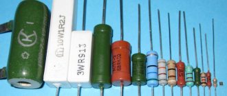
Various resistors
If there are 4 stripes, the last one indicates the accuracy of the resistor. If there are 5 stripes, the third means the third sign of resistance, the fourth is the decimal multiplier, the fifth is the accuracy. The sixth bar, when present, indicates the temperature coefficient of resistance (TCR). If this strip is 1.5 times wider than the others, then it indicates the reliability of the resistor (% failures per 1000 hours of operation). It should be noted that sometimes there are resistors with 5 bands, but standard (5 or 10%) accuracy.
In this case, the first two stripes set the first digits of the denomination, the third - the multiplier, the fourth - the accuracy, and the fifth - the temperature coefficient. Since the resistor is a symmetrical part, the question may arise: “Starting from which side should you read the stripes?” For four-band marking of ordinary resistors with an accuracy of 5 and 10%, the issue is resolved simply: a gold or silver stripe always appears at the end. For a three-line code, the first line is closer to the edge of the resistor body than the last.
Resistor color coding table
Why are identification marks needed?
Studying a typical low power component (0.05 or 0.125 W) will help clarify the reasons for the color coding of resistors. With a length of 3-5 mm, the diameter of the element is 0.8-1.2 mm.
Marking of SMD resistors
To present information in abbreviated form, you can use “classic” encoding. The nominal value of 2,200 kOhm is converted to “2K2”. Here “K” not only denotes the multiplier prefix “kilo-”, but also serves as a separating comma - 2.2 kOhm.
It is difficult to apply clear numbers and letters on a curved surface with a limited area. The slightest defect complicates correct and quick identification. It is enough to make a small scratch during dismantling to create additional difficulties.
Color coding has the following advantages:
- simplicity and manufacturability of the application process;
- the ability to provide the necessary information in full;
- ease of reading data with precise identification of individual design elements;
- high resistance to adverse external influences.
To properly study this topic, it is necessary to clarify the definitions of the main technical parameters of passive elements. Nominal electrical resistance is indicated in ohms and derivative multiples using the appropriate prefix. Kilo-ohms is a multiplier of 10 to the third power or 1,000.
The minimal influence of reactive resistance components (inductive and capacitive) is neglected when creating standard electrical devices. Therefore, such indicators are not displayed in coded digital markings. Manufacturers indicate this and other additional data in the accompanying documentation for precision products. They are necessary for accurate calculations of equipment that processes RF and microwave signals.
Power dissipation is an important parameter. It must be taken into account to select a product that corresponds to a certain maximum current in the circuit. If calculated incorrectly, excessive heat will destroy the resistor.
It should be emphasized! The actual value of electrical resistance depends on the temperature of the conductor. However, power is not indicated by color indication.
The possible deviation of the nominal value (tolerance) is selected taking into account the initial requirements for the radio engineering design. The value of this parameter is determined by the color or number of stripes. The corresponding decryption techniques are presented below.
Additional markers indicate:
- MTBF;
- level of dependence of resistance on temperature changes;
- production technology.
Resistor color coding tables
This article will discuss determining the basic parameters for domestic and foreign resistors using color coding tables. To remember the color coding of resistors and other electronic components, you need to pay attention to the fact that after the black stripe (0) and the brown stripe (1) there is a sequence of rainbow colors. Light blue and dark blue colors are not distinguished in the markings, since the color markings of resistors were originally developed in English-speaking countries, where these colors are pronounced the same.
Marking is applied with colored rings. It is determined in accordance with the requirements of IEC Publications 62. The markings are read from left to right. Resistors with a tolerance value from 0.05 to 10% are made of five color rings: the first three rings determine the resistance value in ohms, the fourth ring is the multiplier, the fifth ring is the tolerance.
You can also find resistors with five bands, but with a standard 5 or 10% accuracy. In this case: the first two rings indicate the resistance value in ohms, the third - the multiplier, the fourth - accuracy, the fifth - tolerance. For resistors with a tolerance value of ±20%, markings with four color rings are provided: the first three rings indicate the resistance value in ohms, the fourth ring indicates the multiplier. For resistors with three color rings, the tolerance value is not specified. For such resistors: the first two rings indicate the resistance value in ohms, the third ring is the multiplier.
Sometimes the temperature coefficient of resistance (TCR) can also be indicated for resistors; in this case, the resistor is marked with six color rings, the sixth color ring indicates the TCR. A special case is the use of color marking of resistors - zero resistance jumpers. They are indicated by one black (0) stripe in the center. Visually, the power of a resistor can be determined by its size.
Example of resistor markings
Color coding of resistors
A simple calculator for calculating resistor values by color. By clicking on the colors in the table, we color the resistor with stripes. As a result, we get the value and tolerance of the resistor we need.
The first stripe from which the count is taken is usually wider or located closer to the resistor terminal.
| 1st lane | 2nd lane | 3rd stripe | 4th lane | 5th lane |
| silver | ||||
| golden | ||||
| black | ||||
| brown | ||||
| red | ||||
| orange | ||||
| yellow | ||||
| green | ||||
| blue | ||||
| violet | ||||
| grey | ||||
| white |
Universal color chart
There is a universal color table that allows you to quickly calculate the values of each resistor if necessary.
When creating such a table, the following fields are selected:
- The color of the ring or dot applied. In this case, both the name and an example are given.
- Depending on the value of the color, it is possible to convert the color coding into a numerical value. This is necessary when creating a diagram for symbolizing denominations.
- The multiplier allows for a mathematical calculation of what resistance the design in question has.
- Also, for almost every color there is a field that indicates the maximum deviation from the nominal value.
It is worth remembering that each color can indicate a number in the marking, a multiplier value, or a maximum deviation.
Examples
Example 1:
Let us consider the use of such a table using the following example: brown, black, red, silver. We read the rings from left to right, the resulting value is always encoded in Ohms.
According to the data from the table, we carry out the following decoding:
- The brown color in the first position represents both the digit and the multiplier. In this case, the number will be “1” and the multiplier “10”. It is worth noting that the following colors cannot be used in the first position: black, gold or white.
- The second color means the number of the second digit. Black means "0" and is not used in calculations. Having such data, we can conclude that the resistor has the alphanumeric marking 1K0.
- The third color determines the multiplier. In our case, it is red, the multiplier of this color is “100”.
- The last color means the maximum tolerance for deviation, and the silver color corresponds to 10%.
Using the table, we can say that the resistor in question is marked 1K0 and has a resistance value of 1000 Ohms (10*100) or 1 kOhm, as well as a tolerance of 10%.
Example 2:
Another more complex example is the calculation of the nominal values of the following resistor: red, blue, purple, green, brown, brown. This marking consists of 6 rings.
When decrypting, we note the following:
1 ring, red – number “2”.
2nd ring, blue – number “6”.
3rd ring, purple – number “7”.
We select all numbers from the table. When they are combined, we get the number “267”.
4 ring is green
In this case, we pay attention not to the numerical value, but to the multiplier. Green color corresponds to a multiplier of 105. We carry out the calculation: 267 * 105 = 2.67 MOhm.
5 ring is brown and corresponds to a maximum deviation of 1% in both directions.
Line 6 is brown, which corresponds to a temperature coefficient of 100 ppm/°C.
From the above example, we can say that deciphering the markings is not difficult, and the number of rings has virtually no effect on how complex the calculations will be. In this case, the resistor has a resistance of 2.67 MΩ with a deviation in both directions of 1% at a temperature coefficient of 100 ppm/°C.
The procedure can be simplified by using special calculators. However, not many people do the 6 ring calculation, which is worth considering.
The nominal series of resistors can be called the result of standardization of nominal values. Fixed resistors have 6 similar rows. Also, one row for variable denominations and a special row E3 have been introduced.
Using the example given denomination, let's decipher it:
- The letter “E” means that marking is carried out according to a series of denominations. This beech is always included in the designation.
- The numbers after the letter indicate the number of nominal resistance values in each decimal interval.
There are special tables displaying nominal series.
To identify standard series, GOST 2825-67 was adopted. At the same time, we can highlight several of the most popular standard series:
- Row E6 has a deviation in both directions of 20%.
- Row E 12 has a permissible deviation of 10%.
- The E24 series has a maximum permissible deviation in both directions of 5%.
The subsequent rows E48 and E96, E192 have a deviation rate of 2%, 1%, 0.5%, respectively.
Marking of SMD resistors
First of all, you should pay attention to the relatively new and not everyone is familiar with the EIA-96 marking standard, which consists of three characters - two numbers and a letter. The compactness of writing is compensated by the inconvenience of deciphering the code using a table.
Three-character marking EIA96
EIA-96 planar element coding (SMD)
provides for determining the value of three marking symbols for precision (high-precision) resistors with a tolerance of 1%.
The first two digits - the denomination code from 01
to
96
corresponds to the denomination number from
100
to
976
according to the table.
The third character - a letter - is the multiplier code. Each of the letters X
,
Y
,
Z
,
A
,
B
,
C
,
D
,
E
,
F
,
H
,
R
,
S
corresponds to a multiplier according to the table.
The resistor value is determined by the product of the number and the multiplier. The principle of decoding SMD resistor codes of the E24
and
E48
is much simpler, does not require tables and is described separately below.
An online calculator is offered for decoding resistors EIA-96
,
E24
,
E48
.
Resistance 0 ohm ±1%, EIA-96
as a result of calculation means incorrect input.
Enter the EIA-96
(case insensitive), either 3 digits
E24
or 4 digits
E48
Resistance: 165 ohm ±1%, EIA-96
Table EIA-96
| CodeNumberCodeNumberCodeNumberNumberNumber 01 | 100 | 25 | 178 | 49 | 316 | 73 | 562 |
| 02 | 102 | 26 | 182 | 50 | 324 | 74 | 576 |
| 03 | 105 | 27 | 187 | 51 | 332 | 75 | 590 |
| 04 | 107 | 28 | 191 | 52 | 340 | 76 | 604 |
| 05 | 110 | 29 | 196 | 53 | 348 | 77 | 619 |
| 06 | 113 | 30 | 200 | 54 | 357 | 78 | 634 |
| 07 | 115 | 31 | 205 | 55 | 365 | 79 | 649 |
| 08 | 118 | 32 | 210 | 56 | 374 | 80 | 665 |
| 09 | 121 | 33 | 215 | 57 | 383 | 81 | 681 |
| 10 | 124 | 34 | 221 | 58 | 392 | 82 | 698 |
| 11 | 127 | 35 | 226 | 59 | 402 | 83 | 715 |
| 12 | 130 | 36 | 232 | 60 | 412 | 84 | 732 |
| 13 | 133 | 37 | 237 | 61 | 422 | 85 | 750 |
| 14 | 137 | 38 | 243 | 62 | 432 | 86 | 768 |
| 15 | 140 | 39 | 249 | 63 | 442 | 87 | 787 |
| 16 | 143 | 40 | 255 | 64 | 453 | 88 | 806 |
| 17 | 147 | 41 | 261 | 65 | 464 | 89 | 825 |
| 18 | 150 | 42 | 267 | 66 | 475 | 90 | 845 |
| 19 | 154 | 43 | 274 | 67 | 487 | 91 | 866 |
| 20 | 158 | 44 | 280 | 68 | 499 | 92 | 887 |
| 21 | 162 | 45 | 287 | 69 | 511 | 93 | 909 |
| 22 | 165 | 46 | 294 | 70 | 523 | 94 | 931 |
| 23 | 169 | 47 | 301 | 71 | 536 | 95 | 953 |
| 24 | 174 | 48 | 309 | 72 | 549 | 96 | 976 |
| 0.001 | |
| Y or R | 0.01 |
| X or S | 0.1 |
| A | 1 |
| B or H | 10 |
| C | 100 |
| D | 1000 |
| E | 10000 |
| F | 100000 |
Online calculator
Interface of the program “Resistor 2.2”
Modern technologies today greatly facilitate the work of both professionals and radio amateurs. In addition to accessible measuring equipment, today in Internet resources dedicated to radio engineering there are a huge number of online calculators for determining the resistance of resistors by marking.
Simple, and generally reliable programs allow you to accurately determine the rating of almost any radio component; more advanced and powerful engineering programs used in packages for design engineers allow you not only to find out the resistance value, but also to find an appropriate replacement and determine the option the performance of the circuit itself.
One of such programs is the Resistor 2.2 program; it is simple, convenient and does not require deep knowledge of computer technology. A simple interface and convenient working elements allow you to work both online and without it.
How to use?
Like most applied engineering programs, the Resistor 2.2 program is an online calculator that allows you to determine the resistance value using various most common types of encoding:
- Standard 4 or 5 color markings.
- Philips branding of various types of resistances.
- Non-standard color coding from Panasonic, Corning Glass Work.
- Regular code marking.
- Regular encoding Panasonic, Philips, Bourns.
After unpacking the archive, the program, which does not require registration, is immediately ready to work. In the window, from the proposed options, the desired parameter is selected and further identification is made using the existing code on the element body.
For ease of identification, an image of the defined encoding is clearly shown in the upper window. Color rings are applied to the body of the radio component in accordance with the values specified by the user, thus making it possible to visually compare the encoding with the real element.
The numerical value of the element's denomination is immediately displayed at the bottom.
Three-character marking E24. Tolerance 5%
Three-digit marking. The first two digits are the denomination number. The third digit is the decimal logarithm of the multiplier. 0=lg1, multiplier 1. 1=lg10, multiplier 10. 2=lg100, multiplier 100. 3=lg1000, multiplier 1000. Etc., according to the number of zeros of the multiplier. The product of the number and the multiplier will determine the resistor value. For this article, use the calculator window above as for EIA-96.
Four-character marking E48. Tolerance 2%
The marking consists of four numbers. The first three digits are the denomination number. The fourth digit is the decimal logarithm of the multiplier. 0=lg1, multiplier 1. 1=lg10, multiplier 10. 2=lg100; Multiplier 100. 3=lg1000, multiplier 1000. And so on, according to the number of zeros of the multiplier. The product of the number and the multiplier will determine the resistor value. E48 only
), or enter 4 digits in the common top window.
Enter the code of SMD resistor E48
Resistance: 22.2kΩ ±2%, E48
Color coding of resistors
In circuits, resistance markings with colored stripes have recently been used. This is convenient, since the colored stripes are drawn around the resistor and you don’t have to unsolder and rotate the resistor to find the numbers indicating the value, as was the case before.
Sometimes a resistor burns out, goes dark, or even worse - a fragment breaks off from it with the required number, but here everything is more convenient. The color of the strip can be seen even when darkened.
Table for determining resistance values using colored stripes
| Color code | Nominal resistance, Ohm | ||||
| Tolerance | |||||
| 1digit | 2digit | 3digit | Factor | % | |
| Silver | — | — | — | 10e-2 | +/-10 |
| Golden | — | — | — | 10e-1 | +/-5 |
| Black | — | — | — | 1 | — |
| Brown | 1 | 1 | 1 | 10 | +/-1 |
| Red | 2 | 2 | 2 | 10e+2 | +/-2 |
| Orange | 3 | 3 | 3 | 10e+3 | — |
| Yellow | 4 | 4 | 4 | 10e+4 | — |
| Green | 5 | 5 | 5 | 10e+5 | +/-0.5 |
| Blue | 6 | 6 | 6 | 10e+6 | +/-0.25 |
| Violet | 7 | 7 | 7 | 10e+7 | +/-0.1 |
| Grey | 8 | 8 | 8 | 10e+8 | +/-0.05 |
| White | 9 | 9 | 9 | 10e+9 | — |
three, four, five and six to indicate the resistance rating .
Mainly four colored stripes are used. Check out the examples below:
You can download a free program to determine resistance using colored stripes.
Transcription examples
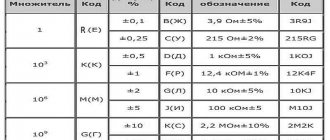
- 3R9J - nominal 3.9 ohms with an error of 5%, which is specified by the letter “J”. Whereas “R” makes it clear that the multiplier is equal to one, and indicates the fractional part - this is where the comma is placed.
- 1K0J – here there is already a coefficient of 103, which introduces “K”. We multiply, and it turns out that the maximum ERE provides 1000 Ohms or 1 kOhm. Well, the tolerance, as you already understood when you saw “J,” is 5%.
- 215RG is a 215 ohm part, as evidenced by the “R” separator, manufactured to within 2% accuracy, judging by the “G”.
- M10J – here the letter “M” determines the coefficient of 1000000 or 106, and it is located in front of the number, that is, it is also a comma, that is, our million Ohms must be multiplied by 0.1; the result is 100 kOhm or 0.1 MOhm, although this recording option is less common.
- 12K4F is an example of the fact that marking resistors and deciphering their designations will turn into a problem if you do not pay attention to the nuances; in this case - to the location “K”, because this is not only an indicator of 103, but also a separator. Therefore, the nominal value is 12.4 kOhm, while the error is only 1%, which is what “F” tells us.
- 1T0M - “T” here indicates a multiplier of 1012, that is, teraOhm, which is usually referred to in abbreviation as simply TOM.
- 2M2K - here the tolerance is already familiar to us, 10%, you need to look first of all at the letter “M”; since it is located between the numbers, it is not only a coefficient, but also a comma. So we get that 2.2 must be multiplied by 106, the result is 2.2 MOhm.
The principle is clear, plus, to make the process easier, you can substitute the Cyrillic alphabet instead of English letters. Then all that remains is to remember that “E” and “R” are equal to one, and the others are quite consistent with SI.
Color code for resistor markings
Its appearance greatly simplified the application and, most importantly, the reading of symbols; Over time, it became the standard for mass production, as it is convenient for the production of large batches of small-sized ERE. They began to use it in the territory of the post-Soviet space, and this solved another problem - it is no longer necessary to take into account the country of origin, and any original features of production in a particular state.
In accordance with it, several rings are made on an electronic component - from three to six, depending on the tolerance, but not counting gold (or silver). They are temperature coefficients and original guidelines: the part must be positioned so that they are on the right.
Typically, resistors are color coded in 4 stripes, less often in 5-6, since these resistors are manufactured with less error and are installed in especially critical circuits, that is, not so often. The main thing is that each line says something important:
- the first, second (and third) determine the denomination, the numerical value of which varies depending on where and what color scheme;
- the fourth shows the multiplier.
After them there is usually a gap, that is, a relatively wide gap, at the end of which there is one or two more rings - an error and the already mentioned temperature coefficient (which may not exist).
How not to get confused in order and numbers? For this purpose, special graphic “assistants” are provided.
Marking resistors with colored stripes: table of universal values
| Color | Number |
| Black | 0 |
| Brown | 1 |
| Red | 2 |
| Orange | 3 |
| Yellow | 4 |
| Green | 5 |
| Blue | 6 |
| Violet | 7 |
| Grey | 8 |
| White | 9 |
| Silver | -1 |
| Gold | -2 |
This is the basis on which you can quickly calculate the denominations of the required ERE. Please note that it has been compiled taking into account the following points:
- Each option is assigned a specific, non-repeating number.
- The order of colors may vary depending on the specific dimensions of the electrical component, but it is always easy to write down the color scheme as a three-digit number. This figure is subsequently used to draw up a conditional schematic diagram.
- Using the multiplier, you can easily calculate the maximum value of the current load that the ERE can withstand.
- All rings have their own fields with deviations.
To make it clearer how resistors are separated by color markings, the table should be examined using specific examples.
Let's say there is a part with four stripes - we read them from left to right:
- The first, brown, speaks of both the number, “1”, and the coefficient, “10”.
- The second, black, gives us the next digit number, in this case “0”, which is not involved in the calculations. If we draw a parallel with Soviet standards, the code would be 1K0.
- The third, red, is another multiplier; in our situation it is equal to “100”.
- The fourth, silver, determines the error, which here is 10%.
It turns out that this ERE is 1 kOhm or 1000 Ohm (10 x 100) and with a tolerance of 10%.
To reinforce this, let’s look at another color marking of resistances; the decoding of a resistor with 6 rings looks like this:
- The first one, red, says that the starting number is “2”.
- The second, blue, allows us to take the next number, “6”.
- The third, purple, gives “7”, in total - “267”.
- Fourth, green - this is already an indicator of a coefficient equal to 105, respectively, the calculated nominal value is 267 x 105 = 2.67 MOhm.
- Fifth, brown - shows that the maximum deviation is 1% in both directions.
- Sixth, golden – sets the temperature coefficient at 100 ppm/ 0C.
Nothing difficult either, right? From here we draw a logical conclusion: increasing the number of rings almost does not complicate the calculations. By the way, you can also determine the resistor value by color marking online using a special calculator, but for 6 strips it is not always suitable.
The EREs under consideration are both constant and variable, and especially for the latter, an additional series of EZ has been introduced, in which:
- the letter “E” is always present and indicates precisely a special case;
- the numbers after it give an idea of the maximum load withstand, and each of them counts a decimal interval.
Standard components are standardized by the provisions of GOST 2825-67, and, according to it, there are the following nuances:
- in E6, deviation is possible in both directions, up to 20%;
- tolerances in E12 reach 10%;
- the limit values in E24 are even lower - plus or minus 5%.
And this trend continues as the series number increases: for the same E96 the error is already 1%, and for E192 it is even 0.5%.