Flat capacitor
There are many types of capacitors with different shapes and internal structures. Let's consider the simplest and most fundamental - a flat capacitor. A flat capacitor consists of two parallel conductor plates (plates), electrically insulated from each other by air or a special dielectric material (for example, paper, glass or mica).
Characteristics
On the body of the device they usually write about what parameters are typical for it. Other important information from the labeling includes the date of manufacture, the name of the manufacturer, and the type of capacitor.
- Nominal capacity indicator.
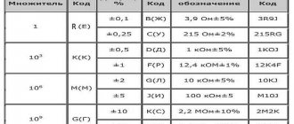
Interesting. One of the most important. GOST 2.702 is the main document regulating this area. On diagrams without indicating units of measurement, capacitance is written if it is in the range from 0 to 9,999 pF. If the range is larger, then microfarads are definitely mentioned. There is also a corresponding marking on the capacitor itself.
You may be interested in Features of spotlights
- Deviations from the nominal value.
- Rated voltage. Thanks to it, it is easier to understand how to determine the capacitance of a capacitor, the formula of which remains the same.
For work, it is recommended to take capacitors that have some margin relative to this parameter. It is not recommended to use devices with a lower value. Otherwise, the dielectric will suffer from breakdown and the device will fail before the specified time.
- Operating temperatures, direct and alternating current are additional characteristics; information about them is not always included on the label.
- Capacitors are single-phase and three-phase, for indoor or outdoor installation.
Internal organization
Capacitor charge. Current
In terms of its purpose, a capacitor resembles a battery, but it is still very different in its operating principle, maximum capacity, and charging/discharging speed.
Let's consider the principle of operation of a flat-plate capacitor. If you connect a power source to it, negatively charged particles in the form of electrons will begin to collect on one plate of the conductor, and positively charged particles in the form of ions will begin to collect on the other. Since there is a dielectric between the plates, charged particles cannot “jump” to the opposite side of the capacitor. However, electrons move from the power source to the capacitor plate. Therefore, electric current flows in the circuit.
At the very beginning of connecting the capacitor into the circuit, there is the most free space on its plates. Consequently, the initial current at this moment encounters the least resistance and is maximum. As the capacitor fills with charged particles, the current gradually drops until the free space on the plates runs out and the current stops completely.
The time between the states of an “empty” capacitor with a maximum current value, and a “full” capacitor with a minimum current value (i.e., its absence), is called the transition period of the capacitor charge.
Capacity formula
The basic formula has already been described above. Capacity is classified as a constant quantity. It is determined by other parameters, for example, the size of the capacitor, design features.
A unit of capacitance is taken to be the capacitance of a capacitor, which has enough charge to produce a potential difference of 1 Volt. This makes it very easy to determine the final numbers.
Horizontal
Flat
Typically, a so-called uniform field is created between the plates inside a flat-plate capacitor. Only near the edges can such a property be violated. These edge effects are often neglected when performing calculations. But this approach is acceptable only if the distance between the plates is small enough compared to the linear dimensions.
A flat capacitor has a capacitance, which is calculated using the formula:
C = (Ee0S)/d.
E0 is a constant electrical quantity.
S is the area of each plate. Design details with a minimum area are often taken into account.
D - designation of the distance between the plates.
Another thing is when the structure is built on several layers of dielectric. Then they are also included in the formula, usually added to the denominator. You also cannot do without volume in such a situation.
Features of application
Spherical
Spherical is a capacitor whose plates are made in the form of two spherical conducting surfaces. The dielectric fills the space between the above parts. In this case, the formula in the denominator contains additional notation R - the radius of each of the plates.
Supercapacitors
Cylindrical
In this case, the plates look like two coaxial or coaxial cylindrical surfaces with a conductive effect. Moreover, the radius of each element is different. And here the space between the different parts is filled with a dielectric. L - designation of the height of the cylinder. And a symbol for diameter is added to the formula. It is measured separately for the lining inside and outside.
You might be interested in the principle of operation of current relays and types of devices
Purpose
Capacitor charge. Voltage
At the very beginning of the charging transition period, the voltage between the plates of the capacitor is zero. As soon as charged particles begin to appear on the plates, a voltage arises between unlike charges. The reason for this is the dielectric between the plates, which “prevents” charges with opposite signs tending to each other from moving to the other side of the capacitor.
At the initial stage of charging, the voltage rises quickly because the high current very quickly increases the number of charged particles on the plates. The more the capacitor is charged, the lower the current, and the slower the voltage rises. At the end of the transition period, the voltage on the capacitor will completely stop growing and will be equal to the voltage on the power source.
As can be seen in the graph, the capacitor current directly depends on the change in voltage.
The formula for finding the capacitor current during the transition period is:
- Ic - capacitor current
- C - Capacitance of the capacitor
- ΔVc/Δt – Change in voltage across the capacitor over a period of time
Capacity and energy of a capacitor.
The most important characteristic is the electrical capacitance of the capacitor. This is a physical quantity that is defined as the ratio of the charge of the capacitor q of one of the conductors to the potential difference between the conductors:
C = frac{q}{Deltavarphi} = frac{q}{U}
The capacitance of a capacitor is measured in Farads, but 1 F is quite large, so capacitance is most often measured in microfarads (µF), nanofarads (nF) and picofarads (pF). And since we have already derived the formula for calculating the voltage, let's express the voltage across the capacitor as follows:
It will be interesting➡ ASKUE: what is it? Principles of organizing ASKUE systems
U = Ed = frac{qd}{varepsilon_0thinspacevarepsilon S}
Here we have d is the distance between the plates of the capacitor, and q is the charge of the capacitor. Let's substitute this formula into the expression for capacity:
C = frac{qvarepsilon_0thinspacevarepsilon S}{qd} = frac{varepsilon_0thinspacevarepsilon S}{d}
If we use air as a dielectric, then in all formulas we can substitute varepsilon = 1.
The following expressions are valid for the stored energy of a capacitor:
W = frac{CU^2}{2} = frac{qU}{2} = frac{q^2}{2C}
In addition to capacitance, capacitors are characterized by another parameter, namely the amount of voltage that its dielectric can withstand. When the voltage is too high, the dielectric's electrons are stripped from the atoms, and the dielectric begins to conduct current. This phenomenon is called capacitor breakdown, and as a result, the plates become short-circuited to each other. Actually, the characteristic that is often used when working with capacitors is not the breakdown voltage, but the operating voltage. This is a voltage value at which the capacitor can operate indefinitely for a long time, and breakdown will not occur.
So, today we looked at the basic properties of capacitors, their structure and characteristics! So this ends the article, and in the next one we will discuss various connection options and markings. Do not miss!
Capacitor discharge
After the capacitor is charged, turn off the power source and connect the load R. Since the capacitor is already charged, it itself has turned into a power source. Load R formed a passage between the plates. Negatively charged electrons accumulated on one plate, according to the force of attraction between unlike charges, will move towards positively charged ions on the other plate.
At the moment of connecting R, the voltage on the capacitor is the same as after the end of the transition charging period. The initial current according to Ohm's law will be equal to the voltage on the plates divided by the load resistance.
As soon as current flows in the circuit, the capacitor will begin to discharge. As charge is lost, the voltage will begin to drop. Therefore, the current will also drop. As the voltage and current values decrease, their rate of decline will decrease.
The charging and discharging time of a capacitor depends on two parameters - the capacitance of the capacitor C and the total resistance in the circuit R. The larger the capacitance of the capacitor, the more charge must pass through the circuit, and the more time the charging/discharging process will require (current is defined as the amount of charge, passed along the conductor per unit time). The higher the resistance R, the lower the current. Accordingly, more time will be required for charging.
The product RC (resistance times capacitance) forms the time constant τ (tau). In one τ, the capacitor is charged or discharged by 63%. In five τ the capacitor is charged or discharged completely.
For clarity, let’s substitute the values: a capacitor with a capacity of 20 microfarads, a resistance of 1 kiloohm and a power source of 10V. The charging process will look like this:
Field away from the edges of the capacitor plates
Since the plates are charged with opposite charges of equal magnitude, the field strength between the plates is the sum of the field strengths of each of the plates.
Outside the capacitor plates, their fields are in opposite directions and the resulting field becomes zero. Thus: Eres=E++E−=2⋅σ2εε0Eres=E++E-=2⋅σ2εε0
We use the relationship between voltage and voltage and tension and the definition of surface charge density
E=UdE=Ud
σ=qSσ=qS
We get $
Ud=qεε0SUd=qεε0S
Where
C=qU=εε0Sd
It will be interesting➡ What is the difference between parallel and series connection of capacitors
Distance between plates
The capacitance of a capacitor is inversely proportional to the distance between the plates. In order to explain the nature of the influence of this factor, it is necessary to recall the mechanics of the interaction of charges in space (electrostatics).
If the capacitor is not in an electrical circuit, then the charged particles located on its plates are influenced by two forces. The first is the repulsive force between like charges of neighboring particles on the same plate. The second is the force of attraction of opposite charges between particles located on opposite plates. It turns out that the closer the plates are to each other, the greater the total force of attraction between charges with the opposite sign, and the more charge can be placed on one plate.
Relative dielectric constant
An equally significant factor influencing the capacitance of a capacitor is the property of the material between the plates as the relative dielectric constant ɛ. This is a dimensionless physical quantity that shows how many times the force of interaction between two free charges in a dielectric is less than in a vacuum.
Materials with a higher dielectric constant allow for greater capacitance. This is explained by the polarization effect - the displacement of the electrons of the dielectric atoms towards the positively charged capacitor plate.
Polarization creates an internal electric field in the dielectric, which weakens the overall potential (voltage) difference of the capacitor. Voltage U prevents the flow of charge Q to the capacitor. Therefore, lowering the voltage helps place more electrical charge on the capacitor.
Below are examples of dielectric constant values for some insulating materials used in capacitors.
- Air – 1.0005
- Paper – from 2.5 to 3.5
- Glass – from 3 to 10
- Mica – from 5 to 7
- Metal oxide powders – from 6 to 20
What other technical designs are there for capacitors?
Constant and variable, tuning - groups of capacitors that are allocated depending on the ability to regulate the main operating parameters. The shape allows us to distinguish between flat and cylindrical, spherical varieties. But the type of dielectric is the main property by which classification is most often carried out.
Imported and domestic developments
Paper
Paper, most often oiled, is the main dielectric for such situations. Capacitors of this type are known for their large dimensions. Without oiling, you can change the characteristic downward. They usually serve as devices with stabilizing and storage functions. But they are increasingly being replaced from modern electronics by film analogues, which are considered more modern.
If there is no oiling, a serious drawback appears - a reaction to air humidity, even if the packaging remains completely sealed. Energy losses increase with wet paper.
You may be interested in this Features of luminous flux
Various characteristics
Dielectrics-organic films
Made from organic polymers, for example:
- Photoroplast.
- Polystyrene.
- Polypropylene.
- Polysulfone.
- Polycarbonate.
- Polyamide.
- Polyethylene terephthalate.
The dimensions of such capacitors are more compact when compared with the previous version. In this case, dielectric losses do not increase, even if the humidity increases. But when overheated, many devices often fail. And if there is no drawback, the purchase of the device is associated with additional costs.
Solid inorganic materials
Examples are glass and ceramics, mica.
The stability and linearity of these characteristics is the main advantage. Some devices even react to the level of environmental radiation. But sometimes such dependence can become a problem. The less pronounced the shortcomings, the more expensive the device is.
Oxide dielectrics
Suitable for the production of tantalum and solid-state capacitors, aluminum models. They differ in such characteristics as polarity. If connected incorrectly, they can quickly fail. The same applies to the situation with a high voltage rating. But these are compact devices with stable operation and sufficient capacity. They can work for about 60 thousand hours if the device is used correctly.
Rated voltage
The second most important characteristic after capacitance is the maximum rated voltage of the capacitor. This parameter indicates the maximum voltage that the capacitor can withstand. Exceeding this value leads to “punching” of the insulator between the plates and a short circuit. The rated voltage depends on the insulator material and its thickness (the distance between the plates).
It should be noted that when working with alternating voltage, it is the peak value (the highest instantaneous voltage value per period) that needs to be taken into account. For example, if the effective voltage of the power supply is 50V, then its peak value will be over 70V. Accordingly, it is necessary to use a capacitor with a rated voltage greater than 70V. However, in practice, it is recommended to use a capacitor with a voltage rating of at least twice the maximum possible voltage that will be applied to it.
What is it needed for
These devices are also distinguished by their wide range of applications. Here are just some of the valid options:
- Storage of analog signals.
- Preservation of digital data.
- The field of telecommunications. In this case, the main function is frequency adjustment, setting up professional equipment.
- Use in creating various power sources.
- Smoothing of rectified voltage at the output of devices. Another question is how the capacitance of capacitors is measured.
Another possible function is the generation of high voltage, which is many times greater than the input parameters. Capacitors can be excellent storage for electrons. Even when the circuit is disconnected from the charge, the energy continues to be stored inside for a long time.
Different sizes