Common wire or ground.
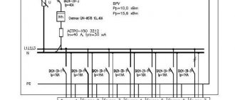
Common wire (ground, body wire) is the designation of the point whose potential is taken as zero. In all other potentials and voltages, they are measured relative to this potential, then the common wire. All exposed live parts of devices and circuits are usually grounded using a protective grounding device, which is connected to the common wire of the devices. Thus, a potential difference cannot arise between these devices, and a life-threatening current will not flow. Figure 1 shows how on a power distribution board all devices are connected by a common zero point using thick copper wires to a copper busbar, which is connected to a ground electrode buried in the ground. This is the common wire of the circuit.
Figure 1. Common wire in the distribution board.
A ground electrode or grounding device protects a person from electric shock. Grounding is also used in cars. In this case, the chassis is used as the common wire. If you look under the hood of the car, you will see how the negative cable of the battery is connected directly to the frame of the car (Fig. 2.).
Figure 2. Common wire in the car.
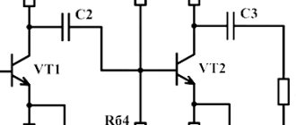
This is the ground or common wire of the vehicle's electrical equipment. Let us repeat once again that the ground is a point in the circuit, the potential of which is taken to be zero and all voltages are measured relative to this point. In electronic equipment, the metal case or chassis also serves as the common wire or ground. In small electronic circuits made on printed circuit boards that are housed in a plastic case, the common ground wire is a copper substrate. Also, general body conductors on printed circuit boards are usually made with as large an area as possible (Figure 3).
Figure 3. Common wire on the printed circuit board.
DID YOU LIKE THE ARTICLE? SHARE WITH YOUR FRIENDS ON SOCIAL NETWORKS!
Related materials:
- Voltage sources
- Connecting batteries and batteries
- Applied voltage and voltage drop across a circuit section.
Comments
Penis 07/19/2018 13:22 Quoting MAX:
Just for the boobies!! not very knowledgeable in these matters)) like me for example)
I even didn’t understand the explanations.
Written as in Wikipedia. Quote MAX 01/22/2016 11:37 Just for the boobies!! not very knowledgeable in these matters)) like me for example)
Quote
John 09/03/2015 08:32 Thank you, well done! For lazy people like me, everything is clear!
Quote
1 12/16/2014 6:17 pm Great article!
Quote
Den 01/14/2014 10:48 thank you for the article, it was very helpful, especially about the board
Quote
Update list of comments
Add a comment
Term: Common Circuit
A common wire is usually a wire that is common to two or more signal circuits.
The main purpose of the common wire is to bind the potential, for example, of a signal transmitter and receiver for local connections.
If the voltage of the useful signal is transmitted relative to a common wire, then the corresponding voltage outputs and inputs are called output or input with a common ground, respectively. Similarly, if the useful signal current is transmitted relative to a common wire, then the corresponding current outputs and inputs are called output or input with a common ground, respectively.
The differential voltage input has a common wire circuit, relative to which the required common mode range of the differential input signal is provided.
It is important that the common wire circuit does not have to be grounded (grounding depends on the specifics of specific devices). For example, the common circuit may belong to a galvanically isolated group of inputs and outputs, but in this case it is recommended to ground the common circuit (but only at one point!) to improve the noise immunity of the equipment, if such grounding does not conflict with the characteristics of this equipment.
If the common wire circuit is grounded, then it is actually a continuation of the signal ground circuit.
Let us take a separate look at the marking of the common wire circuit. There may be markings: “Common,” or “Common,” or “COM” (from English Common). But quite often, the common wires of digital circuits are labeled GND or DGND, and the common wires of analog circuits are labeled AGND. The English Ground, from which these designations were derived, does not automatically mean that these circuits are grounded or should be grounded, but first of all means that we are talking about common wire circuits. In any case, in the product documentation you should always pay attention to the purpose of circuits with such markings (it should be noted that when using new equipment, the most typical errors when connecting it are errors in connecting the common wire circuit, and not in all cases these errors are immediately and clearly manifest themselves, for example, in the case of through currents along common wire circuits).
The term common wire is applied not only to signal circuits, but also to power and control circuits, if we are talking about wires belonging to different circuits.
| Go to other terms | Article created by: | 22.07.2014 |
| About the Terminology section | Latest revision: | 14.02.2020 |
Color designation of wires “plus” and “minus”
To avoid a short circuit in the network, the wires “plus” and “minus” should not be confused under any circumstances. Marking electrical wiring is necessary to quickly and easily determine voltage. This is one of the requirements of the PUE.
To accurately indicate the color blue or green, and “plus” to indicate brown, red, black or white. If the cable has 3 conductors and one yellow with longitudinal green lines, then this is grounding.
Wire marking by color
Important ! Before starting work, it is better to check all wires for voltage, despite the color markings, to avoid the risk of short circuit or electric shock. The wiring may have been done by an inexperienced electrician or a person unaware of the markings, and the colors may not match.
You may be interested in this: Why is potential equalization needed?
There are two types of current in electricity. Direct current cannot be transmitted over long distances, so alternating current is used in everyday life. Direct current is used in the following directions:
- In industry, construction equipment, construction, agriculture;
- In city vehicles (trams, trolleybuses, metro, trains);
- At electrical substations, where it is transformed into alternating current and transmitted to the consumer.
Important! Only two conductors are used in DC networks. There is no phase or zero here, only “plus” and “minus”.
In this case, they use “plus” with red color, and blue indicates the wire with “minus”.
Connecting common wires
The amplifier usually contains several blocks, each of which can have its own power supply, and therefore its own common (ground) wire. There are also common wires in the input and output circuits of these blocks. The question arises: where and how to connect this whole mass of wires. Here, too, not everything is simple, and it will not be possible to give one piece of advice that covers everything. If only because everything very much depends on the specific amplifier circuits and its blocks. Moreover, sometimes the requirements for connecting common wires are quite contradictory, and this contradiction is eliminated only by the appropriate design of the amplifier units. But it happens that this design does not always allow this.
The most important requirement that must be paramount is that the power and signal grounds should never be combined. An example is shown in Fig. 39a. In the first option, the ground of the input connector is connected to the ground of the power supply. Therefore, two currents flow at once through the conductor connecting the grounds of the power supply and the amplifier: the input signal current and the amplifier current. Since the resistance of this wire is not zero, the voltage drop created by the amplifier current will add to the input signal. In the correct version, each current flows through its own wire: separately the input current, separately the amplifier current.
Another rule, somewhat less known: the current of the device must return to where it came from. This rule is illustrated in Fig. 396. In this case, it is more difficult to explain the correctness of such a decision, especially since some not very successful amplifier designs may lead to the wrong option. We can say for sure that in the “wrong” version the cable going to the power source will emit more interference than in the “correct” one.
A typical option for connecting blocks is shown in Fig. 40. It shows the conventional (not electrical) directions of currents with dotted arrows. It is clearly seen that each current flows only in its own circuit, and the ground currents of individual nodes “do not mix.”
However, such inclusion may pose a danger called “ground loops.” What this is is illustrated in Fig. 41. On it, the earthen loop is highlighted with a thick line.
Rice. 41
The danger of an earth loop is that it is a circuit that is equally good at receiving and emitting interference. Moreover, since the resistance of the ground conductors is low, significant currents can flow through the loop.
The question arises: how to evaluate the circuit in Fig. 40 – good or bad? In fact, this is a good scheme and in it the advantage of “separating the earth currents” outweighs the disadvantage of the possible occurrence of an earth loop. However, if the installation is unsuccessful, interference may be noticeable. The influence of such a ground loop can be significantly reduced by circuit design: amplifier circuits sometimes contain resistors that separate the input and output (power) grounds. Much worse (and circuit-technically irreparable) is the formation of an earth loop due to improper installation (Fig. 42.
The conductor shown as a thick line, together with the ground conductors of the blocks, creates an excellent loop.
It must be said that the connection according to the diagram in Fig. 40 gives excellent results when all boards are wired correctly and designed for this connection.
Source: Rogov I.E. Design of power supplies for audio amplifiers. – Moscow: Infra-Engineering, 2011. – 160 p.
Tweet Like
- Previous post: MINIATURE SEALED INTERFERENCE SUPPRESSION FILTERS
- Next entry: UNIVERSAL LED INDICATOR TEST
- AUDIO PREAMPLIFIER WITH AGC (2)
- POWER SUPPLY FOR CAR RADIO (0)
- BATTERY ELECTRICAL ISOLATION DEVICE (0)
- MULTIPLE LITHIUM CELL CHARGER (0)
- BATTERY VOLTAGE LEVEL INDICATOR (0)
- BATTERY STATUS INDICATOR (0)
- CONNECTION DIAGRAM OF A LITHIUM BATTERY FOR POWERING MEMORY DEVICES (0)