Author: Mikhail
01 August 2015 10:57
Tags: Fiber Internet fiber optic Rostelecom installation
30479
33
Do you know how the Internet, telephony or digital television comes to your home? After all, technology has long stepped forward and if we used to connect to the World Wide Web via modems, now a thin wire and the speed of light are enough to transfer data. This is surprising, because when receiving services, we rarely think about how this was done?
0
See all photos in the gallery
Recently, thanks to Rostelecom, we were able to learn more about the mysterious PON technology, which is increasingly conquering the market of digital television, telephony and, of course, the Internet. I’m sharing with you, because as a rule, when someone comes to the sales office of an Internet provider and wants to connect via PON technology to one or several services at once, having simply learned about such an opportunity from an advertisement, they actually have no particular idea about what exactly is he buying? Do you know about this?
Using a stripper, the secondary coating is carefully cut and removed, and then the primary buffer.
0
0
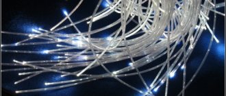
Here it is - fiber, as thin as a hair, which will bring the latest technologies into the home, access to the World Wide Web, as well as telephone communications. This is absolutely amazing!
0
The fiber is cleaned using a lint-free alcohol wipe and chipped using a special device (yes, yes, it is essentially glass!). After that, almost jewelry work occurs - you need to get into the small hole of the connector and fix the fiber there.
0
The connector body is put on
0
0
0
This is where the optical power meter comes into play and the patch cord (signal attenuation level) is measured.
0
But a very interesting device, similar to a large pencil, is a visual damage locator.
Main characteristics of MM fibers
The main parameters of MM OM are described and regulated in rec. G.651. However, rec. G.651, of course, does not reflect all the diversity of MM OV brands. The specifications given in catalogs by manufacturing companies are much more informative.
The parameters listed in the specifications are usually quite clear, but some of them need clarification.
- Fiber type - standard or gradient MM fiber. Sometimes gradient OB is referred to as GIF;
- Working transparency windows - only the used windows are shown: in the vicinity of 850 nm and 1310 nm;
- Attenuation, attenuation gain, bandwidth, chromatic dispersion and group refractive index are given for two wavelengths - 850 and 1310 nm, corresponding to the transparency windows used;
- Broadband or parameter BW (band width) - has the dimension [MHz∙km], i.e. it corresponds to the bandwidth provided by a fiber-optic line over a length of 1 km (this parameter is sometimes called the broadband coefficient, although it is more correct to talk about the relative/normalized bandwidth). For a fiber optic line of length L, the actual bandwidth provided is calculated as BW/L, i.e., it is inversely proportional to the length of the line. This parameter is normalized only for MM OFs, for which it is difficult to calculate the equivalent mode dispersion. Corning often lists the guaranteed transmission distance of gigabit (GE) or 10 gigabit (10GE) Ethernet, which is more informative because it takes into account the actual BW of the Ethernet signal.
- Dynamic fatigue is a dynamic fatigue resistance factor that determines the ability of the fiber to withstand long-term mechanical loads (the higher n, the greater the reliability of the fiber).
If we detect damage, it will be visible visually: the area will glow.
0
0
0
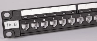
The assembled connector (with cable) is mounted into an optical socket, pull-out box or cassette from which the subscriber's optical terminal will be directly connected. We can say that we have come to the last step in achieving the desired PON system in the house.
0
For this purpose, a connecting patch cord with different polishing is used; a connecting patch cord is used when installing a socket, when installing a pull-out box or inserting a cable into a terminal cassette; the cable is immediately terminated with a connector with APC polishing and a more advanced optical power meter is a universal tester-smartphone on the platform Android. Using it, you can not only take measurements, but also demonstrate to the subscriber the operation of the Wi-Fi service, the operation of the website, etc.
Classification of industrial types of optical fibers
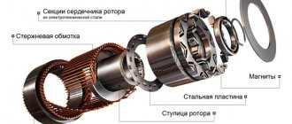
An optical fiber or light guide is a flexible and transparent (glass or plastic) cylindrical rod with a circular cross-section. It consists of three layers: core, shell and cover.
In communication systems, optical fiber is the main medium for signal transmission. The signal - an intensity modulated light wave - propagates mainly inside the core with a diameter of 6 to 62.5 μm (depending on the type of fiber), or more precisely, along a cylindrical waveguide formed by the core and cladding, using the phenomenon of total internal reflection (TIR) of light from the core-shell interface.
There are four main parameters by which fiber types are usually classified:
- by the number of types of waves or modes propagating in them: multimode (MM) and single-mode (SM);
- according to the refractive index profile: step, parabolic (gradient) and special;
- by type of dispersion parameter characteristic D: SF (standard), DSF (zero dispersion shifted), NZDSF (non-zero dispersion shifted) and ZWP (zero water peak);
- by the sign of the dispersion parameter D: for the types of optical fiber listed above, it is positive in the region of operating wavelengths, and for DSF, the dispersion compensation fiber D is negative; this special type of optical fiber is used in DCM dispersion compensation modules.
In addition, there are a number of other special-type agents with highly specialized purposes.
Classification of multimode fibers
MM fibers according to their refractive index profile are divided into:
- fibers with a stepped (rectangular) refractive index profile;
- fibers with a smoothed (quadratic parabola type) refractive index profile, also called gradient.
In addition, they are (conditionally) divided into four classes depending on the OM material:
- class A1: glass/glass, core/cladding diameters: 50/125, 62.5/125, 85/125 and 100/140 µm;
- class A2: glass/glass, core/shell diameters: 200/240 µm;
- class AZ: glass/plastic, core/shell diameters: 200/280 microns;
- class A4: plastic/plastic, core/shell diameters: 980/1000 microns.
In telecommunication systems, class A1 fibers are used almost exclusively (almost only the first two sizes). Given the relatively high attenuation of MM fiber, it is used when laying inside objects or over short distances of up to 1–2 km. In this regard, its main consumer is local networks, and not communication networks focused on single-mode fiber optics.
In addition, the ISO/IEC 11801 standard (starting from version 2002) has defined four categories of MM OB: OM1, OM2, OMZ and OM4 and, accordingly, four classes of MM OB channels, differing in the value of bandwidth. The maximum class for this parameter allows multimode OBs to provide a Gigabit Ethernet (GE) transmission range of 3 km.
Classification of single-mode OBs
OM fibers are usually made of quartz glass (SiO2), have a constant cladding diameter of 125 µm, and a core diameter of 7–10 µm, however, the normalized parameter is the mode field diameter (8–11 µm), which better characterizes the losses when light is introduced into the OM and depends on the wavelength (in fact, it is 10–12% larger than the core diameter). Methods for measuring this parameter are defined by standards: European IEC 793-1-C9 and American EIA/TIA-455-164/-165/-167A.
By refractive index profile
- fibers with a stepped (rectangular) PP profile;
- fibers with a special type of PP profile in the shape of a trident, a simple triangle, a segmented triangle, a triangle on a rectangular pedestal, a W-shaped profile, a multi-stage (quad) profile, etc.
Changing the PP profile allows you to change the position of the zero dispersion point, the slope of the dispersion curve and the dispersion value in a specific wavelength region.
According to the dispersion characteristic
RI profiles determine not only the level and nature of the change in dispersion, but also the type of single-mode OF. As a rule, 3 types of profiles are distinguished: for OF without a dispersion shift, with a shift of the dispersion zero into the third transparency window (near 1550 nm) and with dispersion equalization (in a certain range of the third transparency window, i.e. also near 1550 nm). In accordance with this OM fiber is divided into:
- standard single-mode fiber, or undispersion-shifted optical fiber (SF - standard optical fiber, SSF or SSMF - standard single-mode optical fiber;
- OM OB with a shifted point of zero dispersion (DSF - called “dispersion-shifted OB”), the “D” position of the dispersion is shifted to the 1550 nm point;
- OM OB with non-zero dispersion at the point where the DSF has “0” dispersion, but with “0” dispersion shifted to the region of the 3rd window (NZDSF - called “OB with non-zero shifted dispersion”), it has a small and slowly growing dispersion in the operating wavelength range of EDFA optical amplifiers.
Classification of special fiber types
Due to the development of WDM systems and optical amplifiers (OPA), as well as a number of special applications, special types of optical fibers have emerged:
- quartz optical fiber for dispersion compensation - DCF (Dispersion Compensation Fiber) - OF, used in special dispersion compensation modules - MKD or DCM (Dispersion Compensation Module);
- quartz OM doped with erbium - EDF (Erbium Dropped Fiber) - OM used in optical amplifiers of the EDFA type (Erbium Dropped Fiber Amplifier, erbium optical amplifier);
- quartz optical fiber doped with neodymium - NDF (Neodim Dropped Fiber) - optical fiber used in op-amps of the NDFA type (Neodim Dropped Fiber Amplifier, neodymium optical amplifier);
- polarization maintaining fiber - PMF (Polarization Maintaining Fiber) - OB used in a number of fiber sensors that require maintaining the polarization state;
- quartz optical fiber for the UV spectrum (for example, OF, used in the range of 190–250 nm for various applications);
- Bragg fiber - quartz optical fiber with a large cross-sectional area of the core (with a core diameter of 300–800 μm to create light fluxes of high brightness and power, used in measurements and for transporting high-power laser beams);
- photonic crystal fiber - OB based on photonic crystal technology - PCF or PCF (Photonic Crystal Fiber) - a new photonic crystal fiber used to create connecting cords for laser and optical amplifier equipment.
Below we consider the main types and characteristics of modern optical fibers produced (both for backbone communications and special fiber optics) by manufacturing companies Corning, Fujikura and Sumitomo - the most widely represented on the Russian market.
The fiber used by cable manufacturers can be freely selected by consumers to meet their specific needs at the ordering stage. For consumer convenience, information about OF parameters and values recommended by ITU-T standards are usually presented in the form of tables. These tables can be found in the standard descriptions as well as in the fiber manufacturers' specifications.
Subscribe to the VOLS.Expert channel
We show how to correctly install optical couplings and cross-connects, analyze common mistakes, and give useful advice to specialists.
YouTube
Fiber optic line device
A fiber-optic line transmits a light signal created by an LED or laser. An electrical signal is generated in the transmitting device. The end device also needs a signal in the form of electrical impulses. Therefore, you will need to transform the original data twice. A simplified diagram of a fiber optic line is shown in the figure.
The signal from the transmitting device is converted into light pulses and transmitted via an optical line. The power of the emitters on the transmitting side has limitations, so on long lines, at certain intervals, devices are installed that compensate for attenuation - optical amplifiers, regenerators or repeaters. On the receiving side there is another converter that transforms the optical signal into an electrical one.
Single-mode OBs regulated by ITU-T standards
The main parameters of OM OM are described and regulated in rec. ITU-T G.650, G.652–657, which are used primarily for fiber type references in official documents. They, however, provide the main (most often limiting) characteristics of the OM of the corresponding categories (types).
ITU-T (ITU-T) regulates six types of OM OB, namely:
- G.652 (SF type - Standard Fiber) - the standard, most widely used OM OM with the “0” dispersion position at a wavelength of 1310 nm; today there are four modifications of it: G.652.A, G.652.B, G.652.C and G.652.D;
- G.653 (DSF type - Dispersion Shifted Fiber) - OM OB with a “0” dispersion shift to a wavelength of 1550 nm; the main OM OB used in SDH systems using a single carrier; today there are two modifications of it: G.653.A and G.653.B;
- G.654 (CSF type - Cut-off Shifted Fiber) - OM OB with a shift in the cut-off wavelength from 1260 to 1530 nm to increase the mode field diameter (up to 13.7 μm maximum), i.e., the cross-sectional area of the core; in practice it is rarely used, today there are four modifications: G.654.A, G.654.B, G.654.C and G.654.E;
- G.655 (NZDSF type - Non-Zero Dispersion Shifted Fiber) - OM OM with a “0” dispersion shift to the 3rd window (1550 nm), but beyond the region of 1530–1565 nm, where its dispersion is small in magnitude and slope ; OFs are manufactured with symmetrical positive and negative dispersion characteristics for the use of schemes with controlled dispersion; their cutoff wavelength is shifted from 1260 to 1450 nm; widely used in WDM systems using multiple carriers in one fiber; today there are 5 modifications of it: G.655.A, G.655.B, G.655.C, G.655.D and G.655.E;
- G.656 (NDFWT type - Non-zero Dispersion Fiber for Wideband Transport) - OF, formally similar to G.655 type OF, but having a small dispersion in magnitude and slope in a wider range of wavelengths - 1460–1625 nm; designed for broadband WDM and DWDM transport networks;
- G.657 (type - Bending Loss Insensitive Fiber) - OB, formally similar to the standard OB type G.652.D, but intended for access networks and local networks with a horizontal subsystem connecting several buildings; its main feature is significantly reduced losses during macrobending and a reduced permissible bending radius (up to 7.5 mm minimum), facilitating the laying of intra-facility and local networks; in addition, this type of OM has stricter mechanical tolerances; today there are two modifications of it: G.657.A and G.657.B.
Optical fiber catalogs allow fiber optic link designers to navigate the type and parameters of single-mode optical fibers, which manufacturers most often refer to by the name of the standard.
Main characteristics of OM fibers
- Fiber type - one of the 6 types described above. For OM OB with non-zero dispersion bias (NZDSF), the “+” sign means that the dispersion parameter D is positive, the “–” sign means that it is negative, this sign is important for systems that use dispersion control, including using DCM modules dispersion compensation. In addition to these types of optical fibers, manufacturers offer optical fibers such as ZWPF (Zero Water Peak Fiber), a fiber with zero water peak, designed for CWDM systems, which can operate in the band from 1270 to 1625 nm.
- Operating transparency windows - in addition to the window designations, a more precise interval is also indicated, for example 1530–1565 nm, if the optical fiber is optimized for operation within it. At first, windows were understood as narrow regions of minima of the light absorption curve in OF in the vicinity of: 850 nm (1), 1310 nm (2) and 1550 nm (3). Today, the 2nd window is the region of 1270–1325 nm, the 3rd window is 1528–1565 nm, the 4th window is 1565–1625 nm, the 5th window is 1325–1450 nm. For example, OFS AllWave fiber (and other ZWP-type fibers) can operate in four windows: 2–5.
- Attenuation is given both for fixed wavelengths - 1310, 1383 nm (water peak attenuation caused by the hydroxyl group of OH), 1550 nm, and in ranges within windows, which is important for estimating the possibility of using OF in WDM systems. As a rule, two values are given (through a dividing line): the first corresponds to the maximum possible value, the second to the one actually observed in practice (you can rely on it with a high degree of probability).
- The attenuation increase is given (when used in a wide temperature range) for two temperature ranges (–60 – 55 °C) or (–60 – 85 °C) through a dividing line; if one of them is given, then the “–” sign means no data for another range. A similar increase can be caused by other factors, for example, when operating the OC in an aquatic environment or from an excessively small radius of curvature with frequent bending of the OC, etc.
- Cutoff wavelength is the minimum wavelength at which the optical fiber supports the propagation of only one mode of radiation. Both values are given (through a dividing line): for the core and the cable as a whole, or one of them (the “–” sign means no data). The first value is usually higher than the second, which is determined by measurement and serves as a practical reference for the cutoff wavelength. If the cable is used to transmit carriers with wavelengths below the cutoff wavelength, then the optical fiber effectively becomes multimode, and the resulting additional modes can lead to a significant increase in dispersion.
- The zero dispersion wavelength is given according to the standard or estimated based on other data. Together with the zero dispersion slope, it makes it possible to roughly estimate the dispersion value for a particular wavelength using interpolation formulas.
- The region of non-zero dispersion is given for the OM OV, optimized for working with WDM systems in the specified region. Knowing it is important when assessing the influence of the so-called four-wave mixing (related to nonlinear effects) on these systems.
- The change in the dispersion parameter D in the third window is given for the OM OB with non-zero dispersion and corresponds to the boundaries of the specified window. Knowing D is important for calculating the accumulated dispersion over the span (span) - the transmission section covered by a single optical amplifier. Limitations on it are given in the specifications for WDM systems within a parameter called system configuration, for example, 4x33, 5x30, where the first figure is the number of spans per section, and the second is the op-amp budget per span in dB.
- Long Line PMD Dispersion - This parameter gives the statistical value of the PMD in the cable. This parameter is used for a more reliable assessment of the accumulated (over section length) PMD dispersion for high-speed communication systems (10 Gbit/s and above).
- Effective light field area - this parameter is entered as equivalent to the core area for DWDM systems. They use high-intensity laser sources, which leads to an increase in nonlinear effects. To reduce the optical power density, it is necessary to increase the effective area of the light field, which is done by optimizing the refractive index (RI) profile. For example, in LEAF fiber (from Corning), this area is increased so much that it increases the permissible power of the radiation source by 2 dB (the PP profile used is trident).
- Type of refractive index profile - in addition to the rectangular PP profile, in NZDSF fibers, special PP profiles are used to form a relatively flat dispersion characteristic (with a low dispersion value). The most widely used of them are the trident and triangle on a pedestal (ꓥ-profile), formed by using several shells with different RI values.
- The radius of the fiber's own curvature is a parameter that affects the displacement of the center of the fiber when it is laid for welding in a V-shaped groove (the smaller the radius, the greater the displacement).
A number of other parameters - mechanical, accuracy and temperature - are usually reflected to a lesser extent.
Recommendations for the use of optical fibers in communication systems
Previously, all fibers were used mainly in backbone communication systems with PDH, SDH and WDM technologies. Today they have begun to be used in access networks - PON, FTTB, FTTH with Ethernet, IP, ATM technologies and local networks. Here is a brief summary of recommendations that have accumulated in the process of using OM in them:
- MM OBs are used today only in local networks and access networks and are practically not used in PDH, SDH and WDM networks, although they were previously used in PDH networks, as a rule, in the 1310 nm window.
- SF fibers (rec. C.652) are the most widely used (although they are the oldest and most widespread types of fibers, they are constantly being improved - for example, SMF-28 Ultra from Corning). In recent years, their actual attenuation has been reduced (to values of 0.17 dB/km) and can meet the requirements of rivers. G.654.
- The latest modifications of SF G.652 have effectively become ZWP fibers and can be used for any application, including CWDM systems and high-speed single-link SDH systems up to speeds of 40 Gbit/s. Their only drawback is large chromatic dispersion (CD) at a wavelength of 1550 nm (17–20 ps/nm/km), which can be eliminated by using DCM dispersion compensation modules or using the dispersion control method. This is the solution that is used not only for SDH, but also for WDM when an old cable network is used.
- DSF fibers (rec. G.653) are widely used for SDH systems (STM-16 and above). However, if in the future there is a transition to WDM systems, then their use is undesirable (due to the pronounced effect of four-wave mixing (FWM), since the dispersion zero lies within the operating range of WDM systems, facilitating the occurrence of FWM).
- CSF fibers (rec. G.654), given the large core area and low attenuation, are intended mainly for transoceanic fiber optic lines, where it is necessary to use a large input signal level to implement long sections. This is the Vascade EX1000 optical fiber from Corning, designed for underwater fiber-optic lines without an op-amp. Its data: type G.654C, attenuation 0.16–0.17 dB/km, flight range up to 310 km (with one EDFA) and up to 400 km (with EDFA-Raman tandem).
- NZDSF fibers (rec. G.655) are optimized for WDM applications. The choice of a specific brand of OF depends on the wavelength range used, since within it the dispersion value should not be zero (to exclude FMC). Within the selected range, it should be of the same sign and be at least 2–4 ps/nm/km.
- NDFWT fibers (rec. G.656) are also designed to work with WDM. They make it possible to increase the carrier spacing and thereby use higher transmission rates used for multiplexing in WDM systems, however, the question of creating wideband op amps remains open.
- BLIF fibers, sometimes referred to as BIF (rec. G.657), are optimized for operation in local networks and for use in intra-facility wiring, since when laid within a building one may encounter forced macrobends along the fiber-optic cable route.
- From the point of view of using optical fiber for medium-speed SDH systems (up to 2.5 Gbit/s inclusive - STM-16), it can be stated that with one carrier, any optical fiber can be used that satisfies the customer’s requirements in terms of attenuation and accumulated dispersion. If you intend to subsequently move to WDM, then you can use any fiber except DSF, using alternative technical solutions: either SSMF fiber + DCF fiber, or NZDSF fiber with a low D curve slope, or alternating NZDSF+/NZDSF– (dispersion control method ) - the specific choice is dictated by economic considerations.
- From the point of view of using OF for high-speed SDH systems (10 Gbit/s and higher, i.e. at the STM-64, STM-256 level), it can be stated that with one carrier any OF can be used that satisfies the attenuation accumulated dispersion and the value of polarization mode dispersion - PMD (it must be no worse than 0.1–0.2 ps/km-1/2) or the tolerance for its accumulated value according to customer requirements. If you intend to subsequently switch to WDM, then the main requirement remains to limit the accumulated PMD, but otherwise the considerations are the same as in the previous paragraph (the best option would be to use a method with dispersion control).
We recommend that you read the description of Corning fiber products in the corresponding material or on the manufacturer’s website.