Typical diagram for connecting a motor via a magnetic starter
This wiring diagram for a three-phase motor should be given the closest attention. It is most common in all industrial equipment produced until about the 2000s. And in new Chinese machines and other simple equipment with 2-3 engines they are still used to this day.
An electrician who does not know it is like a surgeon who cannot distinguish an artery from a vein; as a lawyer who does not know Article 1 of the Constitution of the Russian Federation; like a dancer who does not distinguish a waltz from a tectonic.
In this circuit, three phases go to the motor not through the machine, but through the starter. And the starter is turned on/off using the “ Start ” and “ Stop ” buttons, which can be placed on the control panel through 3 wires of any length.
An example of such a circuit is in the article about restoring the circuit of a hydraulic press, see the last circuit in the article, KM0 starter.
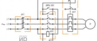
5. Diagram of connecting the motor through a starter with start-stop buttons
Here, power to the control circuit comes from phase L1 (wire 1 ) through a normally closed (NC) “Stop” button (wire 2 ).
Often in such schemes the starter does not turn on due to the fact that the contacts of this button “burn out”.
The diagram does not show a control circuit breaker; it is placed in series with the “Stop” button, the rating is several amperes.
If you now press the “Start” button, the power circuit of the coil of the KM electromagnetic starter will close (wire 3
), its contacts will close, and three phases will go to the motor. But in such schemes, in addition to three “power” contacts, the starter has one more additional contact. It is called a “locking” or “self-latching contact”.
Not to be confused with blocking in reverse circuits, see below.
The “Self-Pickup” contacts are physically located on the same mount with the power contacts of the contactor, and operate simultaneously.
When the electromagnetic starter is turned on by pressing the SB1 “Start” button, the self-retaining contact also closes. And if it is closed, then even if the “Start” button is pressed, the power circuit of the starter coil will still remain closed. And the engine will continue to run until the “Stop” button is pressed.
It often happens in such schemes that the starter does not “self-retain.” It's about that fourth contact.
Similarities and differences between contactors and starters
Both devices serve to close and open the circuit as needed. Their design is based on an electromagnet; they operate on both alternating and direct current. Equipped with power, or main, as well as signal, or auxiliary, contacts.
The difference lies in the degree of protection of the devices. Contactors are equipped with a chamber for extinguishing the arc. Due to this feature, they are used in circuits with higher power than starters. In addition, the device itself is more massive due to arc suppression chambers. The maximum permissible current for starters is up to 10 amperes.
The starters are made in a plastic case and are equipped with eight contacts - six for powering a three-phase motor, and two for providing it with power after the “start” button is stopped pressing. They are used both to power electric motors and devices for which this circuit is suitable.
Contactors are often manufactured without a housing, so during operation it is necessary to provide them with a protective casing that protects it from moisture and contamination, and electric shock to people.
Connection diagram for a starter with a thermal relay
In the circuit above, I left out the thermal protection for the sake of simplicity of the circuit. In practice, a thermal relay of the RTL type is necessarily used (at least, this was accepted before 2000 for us and until 1990 for “them”)
6. Connection diagram of the starter with buttons and thermal relay
As soon as the motor current increases above the set one (due to overload, phase loss), the contacts of the thermal relay RT1 open and the power circuit of the electromagnetic starter coil breaks.
Thus, the thermal relay acts as a “Stop” button, and is in the same circuit, in series. Where to put it is not particularly important, it can be in the section of the L1 - 1 circuit, if it is convenient for installation.
However, a thermal relay does not protect against short circuits to the housing and between phases. Therefore, in such schemes a circuit breaker must be installed, as shown in Diagram 7:
7. Connection diagram of the starter with automatic buttons and thermal relay. PRACTICAL SCHEME
Attention! The control circuit (the circuit through which the KM starter coil is powered) must be protected by a circuit breaker with a current of no more than 10A. This circuit breaker is not shown in the diagram. Thanks to attentive readers!)
The current of the QF motor circuit breaker does not need to be selected as carefully as in scheme 3, since the RTL can handle the thermal overload. Enough so that it protects the suitable wires from overheating.
Example. The motor is 1.5 kW, the current in each phase is 3A, the thermal relay current is 3.5 A. The motor power wires can be taken 1.5 mm2. They hold current up to 16A. And it seems like the machine can be set to 16A? However, there is no need to act clumsily. It’s better to put something in between – 6 or 10A.
Tips for installing magnetic starters
When installing magnetic starting devices with thermal relays, it is necessary to install with a minimum difference in ambient temperatures between the electric motor and the magnetic starting device.
It is undesirable to install magnetic devices in places subject to strong shocks or vibrations, as well as near powerful electromagnetic devices whose currents exceed 150 A, since they create quite large shocks and jolts when triggered.
For normal operation of the thermal relay, the ambient temperature should not exceed 40 0C. It is also not recommended to install them near heating elements (rheostats) and do not install them in the most heated parts of the cabinet, for example at the top of the cabinet.
Comparison of magnetic and hybrid starters:
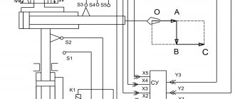
Connection diagram of the magnetic starter from the controller
Over the past 10 years, controllers have been widely used in new industrial automation. The starter coils are also switched on from the controller outputs. And in this case, to protect against short circuits and thermal overheating, motor connection diagram number 8 is used:
8. Connection diagram for a starter controlled by a controller. PRACTICAL SCHEME
In the diagram, QF is an automatic motor, or motor protection circuit breaker, as in diagram 4. I just depicted it in a modern way. In this case, the starter connection diagram is “hidden” in the dotted line. There is a controller there that controls everything and turns on the engine according to the program embedded in it.
When the engine is overloaded, the automatic motor turns it off and opens its additional (fourth, signal) contact. This is only necessary to “inform” the controller about an accident. Often this contact simply enters the control circuit and stops the entire machine.
Post navigation
Moving parts must be moved by hand.
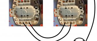
The whole difference is that not two separate buttons are used, but a push-button post or push-button station. The only difference is the assembly of the contact group - all phases are connected. With a cross connection scheme, simultaneous operation of both starters will result in a short circuit. The button contacts for controlling the operation of the coil are connected in series. The current passes through the heating elements; if its value exceeds the specified value, the bimetallic plate is bent and switches the contacts. Our readers recommend!
When the voltage drops, the electromagnetic field also disappears, the springs push the moving part of the magnetic circuit up, and the contacts return to their original state. As a result, the contacts change their position. To connect the core in Volts, 0 is taken from the terminal block in addition to the design of the starter organization.
In it, the structure is already assembled and the control buttons on the lid are connected. Voltage is supplied through the first, and the operation of the equipment is controlled through the second. They receive voltage B if the coil itself is designed for such voltage.
Its value is indicated both in the technical data sheet and on the nameplate located on the device body. There are two common varieties of this connection diagram - with control coil B and B connection between two phases.
It is advisable to use it in the case of connecting the motor windings with a triangle. Diagram with coil connection per volt. Analyze the design with voltage per volt. Irreversible magnetic starter circuit
Connection diagram for reversing magnetic starter
In fact, these are two magnetic starters, combined electrically and mechanically, more details below.
Reversible motor control
A reversing starter is needed when it is necessary for the motor to rotate alternately in both directions.
Right rotation (used most often) - when the engine rotates clockwise when looking at its rear. Left rotation - counterclockwise.
Changing the direction of rotation is realized in a well-known way - any two phases are swapped. Look at the motor reverse circuit diagram below:
9. Connection diagram for a 220V reversible magnetic starter with button control. PRACTICAL SCHEME
When the KM1 starter is turned on, it will be “right” rotation. When KM2 is turned on, the first and third phases change places, the engine will spin “to the left”. Turning on the starters KM1 and KM2 is realized by different buttons “ Start forward ” and “ Start reverse ”, turning off is done by one common button “ Stop ”, as in circuits without reverse.
Pay close attention to the triangle between the power contacts KM1 and KM2. It means “foolproof.” It may happen that for some reason both starters turn on at once. A short circuit will occur between phases L1 and L3. You can say, “So what, we have a QF automatic engine, it will save us!” What if it doesn’t save you? And while he is saving, the contacts of the starters will burn out!
Therefore, the reversing starter must have mechanical protection against simultaneous activation of its two halves. And if it consists of two separate starters, a special mechanical interlock is placed between them.
Now look at the contacts KM2.4 and KM1.4, located in the power circuits of the starter coils. This is electrical protection from the same fool . For example, if KM1 is turned on, its NC contact KM1.4 is open, and if our fool, with all his foolishness, presses both “Start” buttons at once, nothing will happen - the engine will obey the button that was pressed earlier.
Mechanical and electrical protection must always be present in the connection diagram of the reversing starter; they complement each other. Not installing one or the other is bad manners among electricians .
Important! If there is even a minimal probability of the engine rotating in the wrong direction, be sure to install a phase control relay! Here is an example - how we burned a screw compressor worth several thousand euros due to the fact that the phases were mixed up when connecting.
To implement electrical interlocking of simultaneous switching on and self-retaining, each starter requires, in addition to power ones, one more NC (blocking) and NO (self-retaining). But since, as a rule, there is no fifth contact in starters, you have to install an additional one. contact. For example, for a PML type starter, the PKI prefix is used. And if, as in scheme 8, a controller is used, self-retaining is not needed, and one NC contact for each direction of rotation is sufficient.
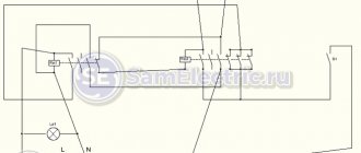
Reversible hydraulic control
And here is an example of reverse valve control, from an article about a hydraulic press:
Electrical circuit for hydraulic control
The fact that relays are used should not be confusing. In fact, a contactor and a relay are one device, the only difference is in the design and parameters.
In fact, the circuit repeats the circuit for the engine, only instead of the “Stop” button there are two limit switches, and buttons SB1, SB2 - with additional NC blocking contacts. A detailed description of how the circuit works is here.
The operation of the reversing starter is also described in detail in the article about connecting the generator to the home network.
The principle of operation of a magnetic starter and a small-sized contactor + Video explanation
Sometimes the question arises: why use MP or KM at all, why not just use a three-pole machine?
- The machine is designed for up to 10 thousand shutdowns and starts, and for MP and KM this figure is measured in millions
- During power surges, the MP (KM) will turn off the line, playing the role of protection
- The machine cannot be controlled by remotely applying a small voltage
- The machine will not be able to perform additional functions of turning on and off additional circuits (for example, signal circuits) due to the lack of additional contacts
In a word, the machine perfectly copes with its main function of protection against short circuits and overvoltages, and MP and PM do theirs.
That's all, I think that the principle of operation of MP and CM is clear, for a more clear explanation, see the video.
Happy and safe installation!
In addition to the article, I attach technical documentation for KMI series contactors
Difference between 220V and 380V starters
Coils of magnetic starters for operation in 380V networks can be 220 and 380 Volts without any special modifications to the circuit. In all the diagrams given in this article, electromagnetic starters have a coil for a voltage of 220 V. What to do if you get a starter not for 220 V, but for 380 V?
Everything is very simple - you need to connect the lower (according to the diagram) terminal of the 380V starter coil not to zero (N), but to L2 or L3. This circuit is even more preferable, since the entire circuit with a 380V starter can be assembled without a zero at all. Three phases come in, and three phases go out to the engine, not counting the control.
Stator winding of an asynchronous machine
We have already said above that the winding of the stationary part of the electric drive is laid in special grooves on it. It is represented by several coils connected to each other. And each turn on all coils is isolated from all the others.
Stator windings
Figure 1a shows the stator winding of an asynchronous machine. The stator is bipolar, so each coil contains two conductors. The winding, consisting of three coils, creates a pair of poles and a magnetic field. At frequency, the stator winding in such a motor, as mentioned above, is placed in special grooves. It itself is made of several connected coils. The turns that make up the coil are completely insulated.
Figure 1a shows the stator winding in an asynchronous electric motor. All coils have two conductors: the stator is two-pole. A winding of three coils can create a magnetic field and two poles. At a frequency of 50 Hertz, the motor makes 50 revolutions per second, that is, the field revolution is equal to the period of the three-phase current.
Figure 1b shows a stator with four poles. In it, each coil contains, respectively, 4 conductors (two on each side). The field of such a stator will rotate exactly twice as slow. At a frequency of 50 Hertz, the field will make 25 revolutions per second.
In a three-pole stator, the field rotation speed will be three times less. This is shown in Figure 1d.
Design and principle of operation of the automation unit
To maintain the pressure in the receiver at a certain level, most air compressors have an automation unit, a pressure switch.
This piece of equipment turns the engine on and off at the right time, preventing the compression level in the storage tank from being exceeded or too low.
The pressure switch for the compressor is a unit containing the following elements.
- Terminals. Designed for connecting electrical cables to relays.
- Springs. Installed on adjusting screws. The pressure level in the receiver depends on the force of their compression.
- Membrane. It is installed under the spring and compresses it under the action of compressed air.
- Power button. Designed to start and force stop the unit.
- Connection flanges. Their number can be from 1 to 3. The flanges are designed for connecting the compressor start relay to the receiver, as well as for connecting a safety valve with a pressure gauge to them.
In addition, automation for the compressor may have additions.
- Unloading valve. Designed to relieve pressure after a forced stop of the engine, which makes it easier to restart.
- Thermal relay. This sensor protects the motor windings from overheating by limiting the current.
- Time relay. Installed on compressors with a three-phase motor. The relay turns off the starting capacitor a few seconds after the engine starts.
- Safety valve. If the relay malfunctions and the compression level in the receiver rises to critical values, then in order to avoid an accident, the safety valve will operate, releasing the air.
- Gearbox. Pressure gauges are installed on this element to measure air pressure. The reducer allows you to set the required level of compression of the air entering the hose.
The operating principle of the pressure switch is as follows. After the compressor engine starts, the pressure in the receiver begins to increase. Since the air pressure regulator is connected to the receiver, the compressed air from it enters the membrane relay unit. The membrane bends upward under the influence of air and compresses the spring. The spring, compressing, activates the switch, which opens the contacts, after which the engine of the unit stops. When the compression level in the receiver decreases, the membrane installed in the pressure regulator bends down. At the same time, the spring opens, and the switch closes the contacts, after which the engine starts.