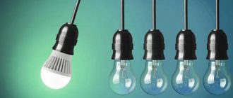
Among all the lamps for artificial lighting of plants, the sodium lamp, which is very popular, is most suitable.
This light source is highly efficient, and is the most economical and durable. The lamp power can range from 30 to 1000 W, depending on the area of use. As for the service life, the lamp life is designed for 25,000 hours of operation. For most greenhouses, this is a profitable option in terms of savings, since the plants need to be illuminated for quite a long time, especially in winter.
Domestic products
Russian Reflex lamps, which are equipped with a built-in reflector, are in great demand on the market. Due to this, the light is directed directly at the plants. The reflector of Reflux lamps has a high efficiency of 95%, which is maintained throughout the entire period of operation. Typically, one Reflax lamp with a power of 70 Watt, suspended at a height of half a meter, is capable of illuminating an area of about 1.6 m2. And since the use of other light sources implies high energy costs, the use of Reflux lamps is more rational. As for the dimensions, Reflax has dimensions of 76x200 mm. Thanks to this, Reflex lamps are best suited for greenhouse owners.
Advantages and disadvantages of sodium lamps
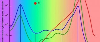
The sodium lamp has significant advantages: • High efficiency. • Stable light flow. • High luminous efficiency of approximately 160 lm/W. • Long service life, which is 1.5 times longer than the service life of other similar lamps. • The lamps have a pleasant golden-white emission. • Effective work in foggy conditions. Due to the fact that the Reflex 250 arc lamp emits a red spectrum, it is an ideal light source for flowering plants, including fruit-bearing ones. And the presence of a blue light spectrum contributes to their active growth and development. In addition, the lamps can operate in a wide temperature range - from -60 to +40 degrees. Along with the advantages, there are also some disadvantages. The main one is the complexity of the connection. The usual method is not suitable here, and there are some peculiarities here. Other disadvantages include the following: • Explosion hazard. • Presence of mercury in the lamp structure. • Long turn-on time, which can be up to 10 minutes. • Not suitable for growing non-flowering or green vegetable crops (radish, onion, lettuce). In addition, if it is necessary to use high-pressure sodium lamps of 250 watts or more, care must be taken to ensure cooling as the lamps become very hot. Although for large greenhouses this disadvantage can turn into an advantage by providing the plants with additional heating.
Ignition devices, IZU
The manufacturer predetermines the switching circuit of the IZU and the maximum cable length. A specific model cannot be switched on according to a different scheme.
To ignite (start) metal halide gas-discharge lamps and high-pressure sodium gas-discharge lamps, a short-term high-frequency voltage of 2-5 kV is applied to them. This voltage is generated by special pulse ignition devices (IZD).
Operating principle of IZU
IZUs are semiconductor high-frequency pulse generators. The capacitor installed in the IZU is charged through a diode and resistor to the required voltage. When the contact closes, a high-frequency capacitor discharges through the primary winding of the transformer. A voltage is applied to the secondary winding, the value of which must be equal to the voltage on the primary winding multiplied by the transformation coefficient (the ratio of the number of turns of the secondary winding to the number of turns of the primary winding). If the transformation coefficient is, for example, 10 (there is 1 turn in the primary winding, 10 turns in the secondary winding), then the pulses on the secondary winding can reach 3 kV.
Thyristors are most often used as contacts, the electrodes of which are supplied with a voltage with a frequency of 50 Hz. The IZU elements and their characteristics are selected in such a way that high-frequency pulses are generated only at specific voltage phases in the network. The total number of high-frequency pulses generated during one half-cycle of the network voltage ranges from one to several tens; The duration of the generated pulses is from several hundredths of a microsecond to several microseconds.
The generated high-frequency pulses from the output of the igniter are supplied to the lamp.
IZU switching circuits
Let's consider a scheme for parallel launch of an IZU . In such a circuit, the lamp current does not pass directly through the IZU, which virtually eliminates any power loss. The circuit of the ignition device for such inclusion is quite simple, the devices themselves are inexpensive, easy to operate and quite reliable. However, high-frequency pulses generated by the ignition device in such a circuit affect, in addition to the lamp, also the choke, which necessitates the use of chokes with increased insulation, resistant to voltages of 2–5 kV.
Since standard chokes for metal halide and sodium lamps do not support this voltage value, the parallel IZU switching circuit is used only with lamps whose ignition voltage is less than 2 kV. First of all, such lamps include high-power metal halide lamps (from 2000 to 3500 W).
We will help you choose lamps for your facility
Pulse ignition devices can also be switched on according to a circuit that does not provide for the presence of a pulse transformer in them , since in such a circuit its functions are performed by a ballast choke equipped with a tap. There is no doubt that the choke in such a connection circuit must be designed directly for operation in it and be equipped with an increased insulation system. TridonicAtco produces similar chokes for metal halide lamps with a power of 35–2000 W and for high-pressure sodium lamps with a power of 35–1000 W, as well as the igniters themselves, designed to work only with these chokes.
sequential circuit for pulse ignition devices is the most common and is used most often. In such IZUs, the secondary winding of the transformer is activated between the inductor and the lamp itself, and the lamp current flows through it. For this reason, in an IZU with such a connection diagram, a certain loss of power necessarily occurs (up to 1 percent of the total power of the lamp), and the IZU elements become very hot. For this reason, the size and weight of a device with a series connection circuit is much higher than that of devices with a parallel circuit connection, or devices based on inductors. However, in a parallel circuit, you can safely use simple chokes without improving the insulation, since the increased voltage is supplied only to the lamp. The production volumes of IZUs with a sequential switching circuit are enormous and account for more than 95 percent of all pulsed ignition devices manufactured in the world.
The quality of operation of ignition devices depends on the following characteristics:
Source
Principle of operation
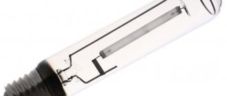
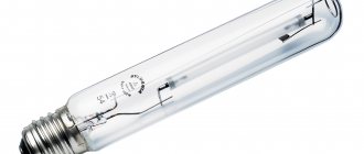
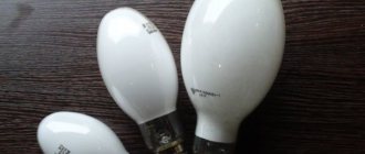
In appearance, sodium light sources are somewhat similar to DRL lamps. There is also a glass flask of an elliptical or cylindrical shape; inside it there is a discharge tube (“burner”), on each side of which there are electrodes. These leads are connected to a threaded base. Due to the fact that sodium vapor has a strong effect on glass, this material is not suitable for making a “burner”. It is made from polycor (polycrystalline aluminum oxide), which increases resistance to sodium vapor and transmits up to 90% of visible light. The DNAT 400 lamp has a discharge tube with a diameter of 7.5 mm and a length of 80 mm. The tube electrodes are made of molybdenum. In addition to sodium vapor, the discharge tube composition contains argon to facilitate starting the lamps, and also contains mercury or xenon, which allows for increased luminous efficiency. During operation, the “burner” heats up to 1300 °C and in order to keep it intact, air is pumped out of the flask. However, it is difficult to maintain a vacuum while the lamp is running, as air can enter through the holes. Therefore, special gaskets are used to prevent this. It is worth noting that when the lamp is operating, its bulb heats up to 100 °C. When the pulse ignition device (IZD) is turned on, a pulse voltage is created, resulting in the formation of an arc. But at first, the sodium lamps DNAT reflex 250 still shine weakly, since all the energy is spent on heating the tube. After 5 or 10 minutes, the brightness of the light returns to normal.
How to connect a sodium lamp
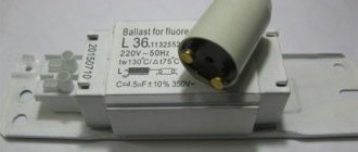
Due to the special structure of gas-discharge lamps, it is not possible to simply connect them to a household electrical network, since the available voltage is not enough to start. In addition, the arc current must be limited. And sodium lamps are no exception. In this regard, it is necessary to use a ballast or ballast in the circuit. They can be electromagnetic (EMP) or electronic (EPG). In practice in Western countries, such devices are called Magnetic Ballast (for electronic ballasts) and Digital Ballast (for electronic ballasts). In some cases, it is impossible to do without the use of a pulse ignition device or IZU. The use of electronic ballasts for sodium lamps 250 is necessary for their heating and further uninterrupted operation. In this case, the startup itself takes 3-5 minutes, and the sodium lighting sources gain full power within another 10 minutes. It is noteworthy that at the moment the lamp is started, its rated voltage increases almost 2 times.
General information about ballasts and lamps.
Manufacturers of IZU, lamps, and ballasts always indicate the connection diagram for the lamp and other components of the ballast kit. Also marked everywhere is phase, zero. Which contact of the lamp is supplied with high voltage voltage. Remember that the HPS lamp is not an ordinary Ilyich light bulb, for which it does not matter how it is connected to the network. Be careful when assembling the gas-discharge paw kit, since if it is connected incorrectly, it will work, and the equipment will lose 70% of its working life and will very quickly fail.
IZU (Pulse ignition device).
Pulse ignition device (IZU) - this device ensures the start of gas-discharge lamps. When turned on, it produces a fairly high voltage pulse of up to 5 kW, this pulse ignites the arc. After the lamp has started, the pulses stop coming. The IZU does not affect the working process of the lamp.
IZU is available in two versions:
1.Parallel type - has 2 contacts.
2. Serial type - has 3 contacts.
Let's now conduct a brief overview of the comparison of Domestic and Imported IZUs.
I would like to immediately give a recommendation, if possible, do not use old IZUs with two contacts, the fact is that the high-voltage pulse emitted by this IZU, when starting a hot lamp, does not go to the lamp, but directly to the inductor, as a result of which the turns may be damaged (broken). windings of the choke coil, and 220 volts will go to the lamp, which can cause it to explode, or at best, burn out!
Nowadays, they mainly produce domestic three-pin IZUs; their price is several times cheaper than imported ones. But the cheap price should be alarming, and rightly so, because our IZUs have a common flaw, the problem itself is that the power of the explosive pulse does not provide a guaranteed start of the lamp, the fact is that it is weaker, and the lamp can start every other time, or after a short time interval. But if you nevertheless installed a domestic IZU, then get ready for the following malfunctions: During an unexpected and short-term power outage, and after it is turned on, the lamp does not start. To start it, the lamp needs to cool down, and only when it’s cold will it start. I draw your attention to the fact that when using a time timer, the IZU data is not suitable precisely because of the malfunction described above.
I recommend using IZUs from fairly well-known manufacturers - Tridonic - Austria, Helvar Finland, Vossloh Schwabe Germany - after you install them, I am more than just confident that problems associated with starting and restarting the lamp will no longer bother you.
The IZUs I recommend have a circuit according to which you can assemble a circuit without problems; imported IZUs are equipped with a terminal block that can be screwed or clamped. The working position is vertical or horizontal, it makes no difference; it is secured using the provided screw and nut. The technical characteristics are indicated on the IZU body, for example, which lamp can light, consider the Vossloh Schwabe Z400 can light a lamp from 70 to 400 Watts, or the Schwabe Z1000 - lights a lamp from 250 to 1000 Watts, HPS or MGL does not matter, in a word, a universal IZU, The operating temperature of which is up to +105 Celsius.
The versatility of the imported IZU lies in the fact that it can ignite any lamp, and works with any choke DNAT, MG, DRL. To ignite a mercury lamp, an IZU is not required; there are universal-use MGL lamps that use a DNAT choke and a DRL for operation.
Length of wire from IZU to lamp
In most cases, I have seen that the specified length of the wire from the IZU to the lamp is quite short, no more than 1 meter. As they say, rules are meant to be broken, and you don’t have to worry about the length of the wire. I have the most ordinary wires for the lamp, which are used for power cords, multi-core, 1.0 mm, each wire in its own insulation and both wires in common. And I set the maximum wire length from the IZU to the lamp:
1. MGL metal halide lamp 10 meters
2. HPS sodium lamp – 40 meters
Imported IZUs look great in a duet with imported ballast; the coincidence of manufacturers is not fundamentally important, but it is desirable. As for me, I used a lamp, ballast, IZU from completely different manufacturers, imported and domestic, and everything worked. As for safety, the IZUshka is not at all dangerous, you can hold it in your hand while working, although it does not work for long at all, some microseconds when the lamp starts and, if necessary, when it is restarted. The IZU is also equipped with different levels of protection. Automatic stops generating high-voltage pulses if, for example, the lamp does not start for 15 minutes (in the event of a lamp failure) and resumes generating them after changing the lamp; it is not necessary to remove the voltage from the network, but again it is advisable.
IZU Failure.
If the IZU fails, it happens silently, and especially not accompanied by any sound effects, and has no characteristic odors. A failed IZU stops generating explosive pulses, and the lamp simply will not start, you can take note: the lamp does not start, the IZU may be dead. Typically, an imported IZU is designed and operates for 800 hours - from this time, only the time during which the IZU generates pulses is taken, and the time it has been hanging idle is not taken into account; one IZU will quite possibly last a lifetime.
Electromagnetic ballast (choke, ballast).
I give preference to our domestic ballasts; the chokes produced in the last 3 years resemble imported ones in appearance. Ballast is the heaviest component, this applies to both weight and price. Chokes exist for DRL and DNAT. For MGL, choke tubes do not exist and will not exist. If you suddenly come across a choke for an MGL lamp in a store, which is much more expensive than, for example, a DRL, then this is pure deception. Since the MGL lamp is designed for a choke from a DRL, or there are still universal switches, such MGL lamps work both with a ballast from a DRL and from a HPS. An MGL lamp that is universally switched on, when operating on a HPS choke, will burn brighter, and the color temperature will decrease, since the current to the lamp will be higher than from the DRL choke. An example for us will be our domestic lamp Reflax DRI 250W/u - universal inclusion. If we work with a choke for DRL-250, the current will be - lamp 2.15A (network 1.0A), luminous flux - 19 lux Kelvin 4500. Now we work with ballast DNAT-250 current will be - lamp 3.0A (network 1.4A), luminous flux – 23.0 lux Kelvin 4000. This is the trick.
Lamp voltage, lamp acceleration.
Quite often the question arises: is it possible to overclock a lamp, that is, can a 250W lamp burn like a 400W lamp! And some, in particular amateurs or novice gardeners, simply do not know about overclocking lamps; I hope my article will provide you with all the necessary skills. I immediately warn you that this method should only be repeated by specialists (electricians, etc.).
The very first thought about overclocking a gas-discharge lamp was born from the fact that the current strength increases directly in the lamp, while in the rest of the electrical circuit the current strength remains without any changes.
Overclocking the MGL lamp
If we install an MGL lamp, for example Narva NCT 250W (2.15A) using ballast DNAT-250 instead of DRL 250, in this case the current changes only on the 3A lamp instead of 2.15A (on the 140 lamp), 1.4A is consumed from the network as before, but a 250W MGL lamp will shine the same as a 400W one. But this overclocking entails a reduction in operating life; the lamp will work not 9000 hours as indicated in the passport, but approximately only 5000 hours. In addition, about once a month it will be necessary to measure the voltage on the lamp with a voltmeter, and at the moment when the voltage reaches 170 - 175 Volts, be sure to replace the lamp without waiting for it to explode! During the start of the MGL lamp, orange flashes occur; similar flashes occur directly in the lamp bulb itself. There are no exceptions, these flashes can be observed by everyone who uses MGL lamps, and I have the same story. The flashes themselves are a factor in the evaporation of sodium and cesium, which penetrates the discharge channel inside the lamp.
Acceleration of the HPS lamp
DNAT-250, the native choke used for it DNAT-250 consumes 3A (On a 100 volt lamp), the ballast takes 1.4A from the general network.
Now we install the lamp DNAT-250 (3A) with a choke DNAT-400 (4.5A) - it will shine very brightly, just not childishly bright, but only 3 months.
DRL choke for HPS lamp.
Testing a 400W HPS lamp on a domestic closed choke for DRL 400, as a result it was revealed that:
1. The brightness of the HPS lamp is reduced by 30%
2. It takes noticeably longer to flare up.
3. The inductor gets hot (the hand does not tolerate it), this is due to the fact that the lamp is designed for 3A, and the DRL inductor produces only 2.15A, as a result of which the load on the DRL inductor increases. BUT the DNaT 400 throttle, oddly enough, also gets hot, and the hand also does not tolerate it.
4. The working life of the lamp is reduced; I recommend replacing it every 6 – 8 months.
5. Use only an imported IZU with three contacts - this is in case a short-term power outage suddenly occurs, as a result of which a two-contact IZU with its impulse can break through the ballast winding.
The tests lasted a year, and nothing terrible happened, the only thing being that the hot ballasts affected the temperature in the greenhouse. During operation, apart from the hot temperature and slight crackling of the IZU, no other factors were identified - such as smell, blinking of the lamp, etc.
Markings on the body
All ballasts have a connection diagram painted on the body or in the form of a sticker; the chokes are also equipped with a terminal block for screws or self-clamping terminals. The working position is vertical, horizontal, technological mounting holes are provided on the body.
In addition to the connection diagram, other technical characteristics of the ballast itself are indicated on the ballasts. For example, “lambda” 0.42(0.44), 0.55 is the modern designation for cosine phi, i.e. Foreign electrical engineers, and ours too, have recently introduced a new concept for lighting calculations - “power factor”, which should be taken in calculations as cos f. Another parameter delta T 70 is the maximum ability to overheat the inductor winding in emergency mode - in this case by 70 degrees. Rated operating temperature +130C. Thus, the throttle will withstand +200C in emergency mode.
Lamp voltage
Carry out current measurements on the lamp only when the IZU has completed its task, otherwise the explosive pulse will burn out your voltmeter. The voltage across the lamp increases by 10 volts after approximately 1000 hours of operation. For overclocking, sodium lamps are mainly used, since they are cheaper than MGL. In any case, you will have to measure the voltage on the lamp; lamps operating in normal mode also require such monitoring. Since over time, a year or two, the halogen components burn out, as a result of which the voltage on the lamp begins to increase and when it reaches 180 V, a load is applied to the inductor, in this case a break in the winding may occur, or a short-circuit - a short circuit in the winding Inductor short circuit can be determined by the unpleasant smell of a burnt winding, as well as by smoke. In this case, your lamp remains with the socket one on one, that is, connected directly to the network, then it burns out, the burner cracks, and the internal wires melt. When installing the throttle, provide a package for it - an automatic opening device.
Phase compensating capacitors.
Basically, imported rather than domestic capacitors have taken a stable place; German produces excellent 250V capacitors of various capacities. The required capacitance of capacitors can be obtained by connecting several capacitors in parallel. I will give an example: we take 2 capacitors with a capacity of 16 microfarads each, connect them in parallel, and as a result we get a capacitance of 32 microfarads, the operating voltage does not change - 250 volts.
Since each ballast requires the required capacitor capacity, there are special tables, but in general, manufacturers have determined this a long time ago, and capacitors are produced with a predetermined capacity.
Capacitors are not indicated on the connection diagrams shown on the diagrams or IZU. The capacitors are connected in parallel to the 220V network, the capacitor is located before the choke, the capacitor increases the cosine phi of the network, and for phase compensation. The electromagnetic ballast itself has a low cosine phi. Previously I wrote that the throttle body indicates such a parameter as “lambda” 0.42 (0.44), 0.55 is the modern designation for cosine phi, i.e. Foreign electrical engineers, and ours too, have recently introduced a new concept for lighting calculations - “power factor”, which should be taken in calculations as cos f. Roughly speaking, the efficiency of the inductor is initially within 50%. This is very little, almost 50% of the electricity consumed is wasted, and you have to pay for false current. A large current flows through the wires, they heat up.
When using an input capacitor (in parallel with the network), the inductor inductance is compensated by the capacitance and the current consumed by the lamp-choke set is reduced by almost 2 times. It is believed that with electromagnetic ballasts you can get a cosine phi, in the best case, no more than 0.92. This is a good indicator.
Electronic ballasts give a cosine phi of 0.98-0.99, i.e. the current will approach the current of a conventional incandescent lamp of 250 watts (if there were such a thing), and the power consumption of the electronic ballast is 2 times less than usual (12 versus 28 watts). But electronic ballasts are less reliable, the electronics are complex and it is not possible to accelerate the lamps there.
Recommended capacitor capacities
For example, the current of an electromagnetic ballast with a HPS lamp is 250 watts without a capacitor of the corresponding capacity (32 μF), consumed from the network is almost 3A, and with it - 1.4A. And so on. With such a capacitor, the starting current of the lamp is lower; at first, when the lamp is cold, the current consumption will be 20-30% higher than after 5 minutes, when the lamp warms up. But without a capacitor, the starting current, for example of a DNAT-400 lamp, can reach 9A.
Below are the recommended capacitor capacities.
Throttle DNAT-250 (3A) – 32 (36-40) uF.
Choke DNAT-400 (4.4A) – 45 (50) uF.
Choke DRL-250 (2.15A) – 20 µF.
Choke DRL-400 (3.25A) – 35 uF.
The containers listed above are the most optimal containers. You probably thought: - I’ll put a larger capacitance on the capacitor and get a higher cosine f, don’t be mistaken, since an excess of capacitance will cause the lamp to blink; if it’s less, then the current consumption will decrease slightly. That is, increasing the capacitance of the capacitors will result in a decrease in efficiency and the occurrence of resonance in the circuit.
Power losses also occur in the throttles themselves.
250 W - about 28 W.
400 W - about 32 W.
The capacitor has fasteners reminiscent of IZU fasteners, double self-clamping terminals, which facilitates the assembly of the circuit itself.
Burnout of HPS and MGL lamps.
The most interesting thing is that lamp failure occurs in different ways:
— the lamp stopped starting, while in the burner you can notice a discharge from the IZU (while it is in operation) resembling blue lightning.
— the lamp begins to blink, and then does not start at all, the outer bulb may also turn black from the inside, and there is a possibility of losing the throttle, although in rare cases.
When they fail, lamps do not explode unless, of course, you touch the outer bulb of the lamp with greasy hands, do not spit on it, and do not splash water on the lamp.
Additions about IZU and chokes.
As I mentioned above, IZUs come in two and three contact types.
Serial IZUs (three contacts) are the best, they can be connected both to a choke with one winding (coil) and to a choke with two windings (coils), they are connected in series.
Parallel IZU (two contacts) are not the best option, but they still work, and it is connected to a choke with two separate windings, why exactly with two windings (coils)? I answer, one winding will be used in phase mode, the second winding operates in zero mode, thereby the breakdown of the inductor insulation goes to almost nothing.
For safety reasons, two-contact IZUs cannot be switched on with a choke that has one winding (coil) or with a choke that has two windings (coils) that are connected in series.
Electronic ballast Electronic starting and control device (ballast)
Scope of application: Replacement of the electromagnetic ballast (EMG) traditionally used in lamps - a choke, a compensating capacitor and a pulse ignition device. Description: Electronic ballasts (EPG) are manufactured on the basis of boards with electronic components and, if necessary, installed in aluminum or steel cases (independent electronic ballast). Advantages of luminaires with electronic ballasts Increased power factor; No inrush currents (does not require IZU) Stable operation of luminaires and lamps during any power surges in the network; Ability to control light output (dimming); Reducing the cross-section of wires and the number of control cabinets; Solving third harmonic problems; Energy savings of 20-30%
Ballast device
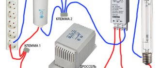
The ballast consists of three main components: • Inductive choke. • IZU. • Phase compensating capacitor. The choke serves to limit the arc current and its power must be the same as that of the lamp used. For example, if a HPS 250 lamp is used, then, accordingly, the power of the inductor should also be no less and no more than 250 Watts. Recently, the connection diagram for lamps often includes a single-winding choke, while double-winding ones are already obsolete. IZU is necessary to increase the voltage to several kilovolts in order to form an arc. The power of the IZU can range from 35 to 400 Watts. In addition, the device can be of a two-pin or three-pin design. Moreover, the use of three-pin IZU is preferable. As for the capacitor, this is an optional component. But its presence provides certain advantages, as it allows you to reduce the load on the household electrical network. In turn, this reduces the risk of a wiring fire to a minimum. More details will be discussed below.
Starting equipment
Due to its structure, DNAT requires additional equipment for connection. This is due to the fact that the light source does not have enough voltage to start, in addition, the arc voltage must be reduced. It is for this purpose that the ballast apparatus, as well as the IZU, are used.
An electronic ballast has many advantages compared to electronic ballasts (electromagnetic). The only drawback is that the first type of device is more expensive.
Chokes help reduce voltage ripple, smooth out the current frequency, or eliminate its variable component. That is, they limit and stabilize electrical voltage. It is enough to simply connect the ballast to the lamp for the device to work without interruption.
Today, outdated two-winding electronic ballasts have been replaced by modern single-winding devices.
The choke must have the same power as the lamp to which it will be connected. Otherwise, the lighting device will fail faster or the light output will decrease. For example, if you purchased a 250W HPS, then the power of the electronic ballasts should be the same.
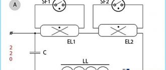
Connection diagrams for HPS lamps
Depending on which IZU is used (with two terminals or three), 250 Watt high pressure sodium lamps can be connected in different ways. This is reflected in more detail in the diagram below.
Sodium lamp connection diagram
As you can see from the figures, the inductor (ballast) is connected in series, but the IZU is connected to the circuit in parallel. To operate, sodium lamps use reactive power. In this regard, it is desirable that the connection diagram include a special capacitor, which will suppress interference and reduce the inrush current. Which ultimately extends the life of the lamps. Also, this element is simply irreplaceable in the absence of a phase compensator. As can be seen in the first figure, the presence of a phase-compensating capacitor is shown by a dotted line. Its connection is carried out in parallel with the power source. The main thing is to choose a capacitor with optimal electrical capacity. For example, when using the same DNAT-250 lamp, its capacity should be 35 microfarads. If the circuit contains a DNaT 400 lamp, then you can choose a capacitor with a slightly larger capacity - 45 μF. It is allowed to use only dry elements in the circuit and designed for a voltage of at least 250 V. When connecting lamps yourself, it is worth taking note of something. The length of the wire connecting the light source itself and the inductor should not exceed one meter.
Common connection errors
In order for the device to work correctly and for a long time, you need to know what mistakes you should not make when connecting it:
- Incorrect connection of the 4-pin ballast. There are chokes on sale that have 4, 5 or 6 contacts. Many beginners connect the phase and neutral wires to one contact, and connect a lighting device from the other. But it's not right. There is a diagram on the device body that you need to follow.
- Installing the lamp into the socket with bare hands. Finger oil on glass turns into dark stains when exposed to high temperatures. Then the risk of cracks appearing in these areas increases. To prevent this from happening, wipe it with a clean cloth before starting.
- Use of ballast with a power higher than that of the lamp. Then the internal bulb will overheat, the device will begin to blink and will soon fail.
- Applications of a choke from an arc mercury phosphor lamp for HPS. If you use a ballast designed for lamps of a different type, the light source will quickly become unusable.
- Lack of capacitor in the kit for DNAT. Then the wires will constantly overheat.
Try to avoid these mistakes so that your equipment will serve you for a long time.
Precautionary measures
Due to the design features of the 250 sodium discharge lamp, extreme caution must be used when operating these light sources. It is unacceptable to turn off the lamp immediately after turning it on. It should remain on for at least 1 or 2 minutes. Otherwise, the lamp will stop turning on altogether and then it must be de-energized and wait a while. In the room where lamps operate, it is necessary to have high-quality ventilation. Its temperature during operation can rise to 100 degrees or more. And according to some sources, all 1000. Therefore, good ventilation is the key to long-term and safe operation of lighting sources. Do not touch high-pressure lamps with your hands during operation to avoid burns. The same goes for its reflector. When installing lighting sources, you do not need to handle the bulb with bare hands; it is best to use cloth gloves. Or you can wrap it in some paper or cardboard to avoid leaving greasy fingerprints on the glass. Since the heating temperature is very high, any grease deposits or even drops of water can cause the lamp to explode. You can find a lot of information about this on the Internet. But not only high-pressure lamps can get very hot, this also applies to the ballast used. Its temperature can rise to 80-150 degrees. Therefore, as a precaution, this element of the circuit should be insulated, hidden under a fireproof and durable casing. This will prevent dry leaves, pieces of fabric or paper, and other objects from getting inside. Don’t forget about basic safety precautions when working with electricity. That is, eliminate any possibility of water getting into the ballast, and monitor the integrity of the electrical wiring. It is always worth remembering that at the moment when the HPS lamp starts, the IZU generates high voltage pulses. Therefore, it is best to use special wires that are designed to work in extreme conditions. They are just designed for high heat.
How to check and connect the IZU for DNAT with your own hands
HPS lamps are the oldest and most time-tested light sources.
They continue to be actively used despite the fact that the lighting equipment market is actively filled with LED devices. The popularity of sodium lamps is due to the fact that they emit an intense luminous flux with minimal power. They are actively used for street lighting and for growing plants in greenhouse conditions. However, due to the low quality of color rendering and strong flicker, HPS is not used for lighting residential buildings and industrial premises.
To connect the HPS, you need to purchase a special starting device (IZU), a ballast (electronic ballast, choke), and a capacitor. When the ignition device is started, a high voltage pulse is created and an arc is formed. IZU for HPS must be selected taking into account the lamp power (from 35 to 400 W). Ignition devices are of parallel or series type, that is, with two or three contacts. It is important to know which device is best suited for HPS and how to connect it correctly.