Insulation testing methods
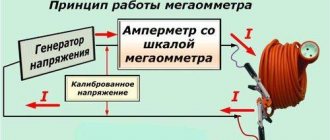
Before applying voltage, to prevent a short circuit, it is necessary to check the insulation between live parts and the body of the electric machine. In three-phase electric motors, the windings are interconnected. To check that there is no short circuit between them, if possible, the windings should be disconnected from each other. The insulation of each of them is checked relative to the other coils and the machine body. The insulation is checked with a megger. For this output, the device is connected to the “megaohm” position. The ends are applied to the terminals and part of the body, which has been stripped of paint.
Information! Instead of a housing, the output can be attached to the shaft of an electric machine.
The measurement is carried out by two people - one person applies the device’s output to the measured elements, and the second turns the device’s handle for a minute, then, without stopping the rotation, readings are taken. If the result is questionable, the measurement should be repeated. Wires and windings have electrical capacitance and are charged from the megger during measurement, therefore, after completing the tests or before re-checking the output of the device and the parts being measured, it is necessary to discharge them by short-circuiting.
Winding resistance measurement
Winding resistance is measured using direct current. This type of measurement is made to check the correctness of the winding and the quality of the connections.
Information! The resistance value, with the exception of the parallel excitation windings of DC motors, is several Ohms, and in high-power electric machines less than 1 Ohm
Measurements are made with a measuring bridge or a digital ohmmeter. When carrying out measurements, it is important to ensure reliable contact of the device’s terminals with the terminals of the electrical machine. Before starting measurements, the outputs of the measuring device are connected to each other, and “0” is set. In three-phase machines, the windings should be disconnected from each other. If this is not possible, they are measured in pairs, through the connection terminals. In commutator electric motors and DC machines, the field windings are divided into two parts and are located on both sides of the rotor. To check the resistance, they are disconnected and measured separately.
Motor temperature
When the temperature changes, the resistance of the windings changes, so the motor temperature when measured should be 20°C or the resistance must be recalculated using special tables. To measure temperature, built-in or additionally installed internal temperature sensors are used. Their number depends on the power of the electric machine:
- up to 10 kW - 1 piece;
- 10-100kW - 2 pcs;
- 100kW-1mW – 3 pcs;
- more than 1 mW - 4 pcs.
The temperature of the device is considered the average value of the readings. When measuring the resistance of a motor that has not been running for a long time, its temperature is considered to be the ambient temperature. However, it should not change by more than 5°C for several days before starting measurements. Measurements are taken several times with a break of at least 2 hours. If the result changes, you should wait until the electric machine reaches ambient temperature.
How to test an electric motor with a multimeter
To identify an electric motor malfunction at home, in the absence of expensive professional equipment, there is nothing left to do but test the electric motor with a multimeter. With its help, you can identify most breakdowns, and you do not have to involve a specialist. So what should you do?
Preparation
Before making a diagnosis, you should:
- De-energize the unit. If the resistance measurement is carried out in a circuit connected to the mains, the device will fail.
- Inspect the engine and find out if it is flooded, if there is a smell of burnt insulation or broken parts, etc.
Calibrate the device, that is, set the arrow to the zero position (the probes must be closed).
Asynchronous, commutator, single-phase and three-phase motors are called using the same method; a slight difference in the design does not play a special role, but there are nuances that must be taken into account.
Stages of work
The most common malfunctions can be divided into two types:
- Presence of contact in a place where there should not be one.
- Lack of contact where it should be.
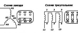
First, let's look at how to test a 3-phase electric motor with a multimeter. It has three coils connected in a delta or star configuration. Its performance is affected by the reliability of contacts, the quality of insulation and correct winding.
- First, check the short circuit to the body (keep in mind, the value will be approximate, since more sensitive instruments are required for accurate readings).
- Set the multimeter readings to maximum.
- Connect the probes to each other to ensure that the settings are correct and the device is working properly.
- Connect one of the probes to the engine housing; if there is contact, attach the second probe to the housing and monitor the readings.
- If there are no failures, touch the probe output of each of the three phases one by one.
- If the insulation is of high quality, the test should show a fairly high resistance (several hundred or thousand megohms).
It must be remembered that when measuring insulation resistance using a multimeter, the readings will be higher than permissible, since the EMF of the device does not exceed 9V. The engine operates at 220 or 380V. According to Ohm's law, the resistance value depends on the voltage, so make allowances for the difference.
Next, check the integrity of the windings by ringing the three ends included in the motor boron. If there is a break, further checking does not make sense, since this malfunction must first be eliminated.
Then check for shorted turns. With a delta connection, the fault indicator will be a higher value at ends A1 and A3. When connected with a star, the device shows an overestimated value in circuit A3.
Knowing how to test an asynchronous electric motor with a multimeter, you will save time and money, since perhaps only minor faults will be detected that you can easily fix yourself.
For more serious and detailed diagnostics, other devices are required, which are rarely used in everyday life due to their high cost.
If you are unable to find damage with a multimeter, contact a professional.
Checking the commutator motor
Now let's move on to the above-mentioned nuances, because engines come in different types. How to test a commutator motor with a multimeter? The scheme for checking it looks like this:
- Turn on the device in Ohm units and measure the resistance of the collector lamellas in pairs.
- Then measure the resistance between the armature housing and the commutator.
- Check the stator windings.
- Measure the resistance between the housing and the stator terminals.
Interturn closure is determined only by a special device. There is a way to measure armature resistance. Remove the brushes from it and apply a voltage of up to 6V to the plates, measure the voltage drop between them.
To check a single-phase motor, ring the working and starting windings. The resistance of the first should be one and a half times lower than the second.
For example, let's take a single-phase motor with three terminals, used in washing machines (usually the old model). If there is very high resistance between the ends, then the coils are connected in series. It remains to find the midpoint and thus determine the ends of each of them separately.
Since electric motors are found in every home in household appliances - this is a refrigerator, a vacuum cleaner, and much more - and they periodically break down, knowing how to check a single-phase electric motor with a multimeter is simply necessary. If the damage is not too serious, it is not advisable to take the device to a repair shop. And you will have the opportunity to gain experience and gain skills by working with engines of different types and modifications.
Measurements with ammeter and voltmeter
If a measuring bridge or ohmmeter is not available, then it is possible to determine the resistance of the windings by measuring current and voltage:
- connect a voltmeter in parallel to the winding, and an ammeter in series;
- apply =5V to the circuit;
- measure current and voltage;
- use the formula R=U/I to calculate the resistance;
- repeat two more times, changing the voltage;
- calculate the arithmetic mean.
Important! If you use alternating voltage instead of constant voltage, you can detect a turn short circuit between adjacent turns.
Checking the integrity of collector electrical machines
Resistance measurements also check the serviceability of AC and DC collector machines. It is advisable to do this with a pointer or digital ohmmeter. During testing, the device readings should not change by more than 10-15%. Measurements are made between adjacent commutator plates or through brushes. If the readings change when taking measurements through the brushes, it is necessary to remove them and take measurements directly on the commutator.
Insulation measurement
When checking insulation resistance, temperature does not matter, but the megger should be checked before and after testing. The resistance value depends on the power of the electric machine and is determined by the formula Riz=Unom/(1000+0.1Рnom), where:
- Unom—mains voltage;
- Rnom - engine power. In practice, it is believed that the stator insulation resistance should be at least 1 mOhm, and there should be no short circuit in the wound rotor windings. If the megger readings are lower than required:
- after an electric machine overheats, it is sent for repair;
- after storage or getting wet, the device is disassembled and dried, after which a re-check is performed. Instruments used to measure resistance Various instruments are used to carry out measurements.
Checking an asynchronous electric motor
In addition to commutator motors, in everyday life you can also find asynchronous motors installed in some models of washing machines or in refrigerator compressors. Much more often they are used in compressors, pumps, various machines and other equipment. Despite their high reliability, these electric motors are also susceptible to breakdowns and malfunctions. In these designs, the role of the armature is played by the stator windings, so visual inspection should begin with them.
Often the windings stop working when they become damp or the turns break. Therefore, if the motor has not been used for a very long time, it is necessary to check the insulation resistance using a megger. In the absence of a mgohmmeter, for preventive purposes it is recommended to disassemble the unit and dry the stator windings for several days.
It is quite possible that the cause of the malfunction does not lie in the electric motor itself, but is associated with some other factors. Therefore, before you start repairing the unit itself, you should make sure that there is voltage, check the magnetic starters, connection cables, and thermal relay. If there is a capacitor in the circuit, it also needs to be checked. If all of the above elements are in good working order, you can begin disassembling the engine for initial inspection. The test must be carried out in a complete absence of power supply. It is necessary to prevent spontaneous or erroneous switching on of the unit.
During the inspection, in addition to other parts, the stator windings are especially carefully checked. They must be intact, without protruding or torn wires
Particular attention should be paid to black spots indicating possible burnt wires. In good condition, the conductors are dark red in color.
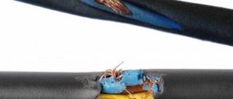
Blackening occurs when the electrical insulating varnish applied to their surface burns out. During inspection, complete or partial burnout of the winding and interturn short circuit may be detected. With partial burnout, the engine will run and heat up quickly. Therefore, the winding is completely rewound in any case.
If the external examination does not produce results, further diagnostics should be carried out using measuring instruments. Most often, a multimeter is used for these purposes to determine the integrity of the winding and the presence or absence of a breakdown in the housing.
In 220V engines, the starting and operating windings are connected. The starting resistance should be 1.5 higher than that of the working one. In 380V electric motors connected by star or delta, the circuit is disassembled, after which each winding is wired in turn. The resistance on each of them should be the same, with a deviation of no more than 5%. Also, all windings must be connected to each other and to the housing. If the resistance value is not infinite, this indicates the presence of a breakdown of the windings on the housing or between themselves. In this case, they require a complete rewind.
The insulation resistance of the motor windings is checked separately. In this case, a multimeter will not help; you will need a 1000V megohmmeter connected to a separate power source. When performing measurements, one wire of the device touches the motor body in an unpainted place, and the other wire is connected in turn to each terminal of the winding. If the insulation resistance is less than 0.5 megohm, then the motor requires drying
When taking measurements, be careful not to touch the test leads. The equipment being measured must be de-energized, the duration of measurements is at least 2-3 minutes
Read also: Is it possible to connect running lights to the dimensions
The greatest difficulty is the search for interturn closure. It cannot be detected by visual inspection. For three-phase motors, special inductance meters are used, which normally show the same value on all windings. If there is damage, the inductance of such a winding will be the lowest.
During the operation of any equipment, breakdowns of various types periodically occur that require high-quality repairs. Electric motors that are common today are no exception. Such units can fail as a result of an interturn short circuit. In such a situation, a seemingly serviceable engine may burn out. That is why specialists try to promptly determine the interturn type short circuit in order to qualitatively eliminate the cause of the malfunction.
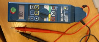
Megger
Used to measure insulation resistance. Electric motors with a rated voltage of up to 1 kW are used with 0.5 and 1 kW megohm meters; high-voltage devices are checked with 2.5 kW megohm meters or special devices. The leads are pressed tightly against the object being measured, and the handle of the device rotates evenly, at a speed of 1.5-2 rpm, until the arrow stops.
Attention! There is a high voltage at the megger terminals - up to 2.5 kW, depending on the design, but a very small current. Therefore, touching them is painful, but not life-threatening.
What is a multimeter
A multimeter or multitester is a compact, ergonomic and multifunctional device for measuring the basic parameters of an electrical network for any purpose. All multimeters allow you to measure current, voltage, resistance and even temperature with a certain accuracy using their probes.
Appearance of a typical dielectric plastic digital multimeter
There are two types of multimeters:
- Analogue, which display measurement results using mechanical display tools: arrows, bars and division values, showing the quantitative characteristics of the measured value;
- Digital. The most commonly used types of devices, the information is displayed through a built-in display, and all data is calculated digitally.
You might be interested in cable wiring diagrams
Megaohmmeter GM3123 for use in industrial high voltage networks
