general information
The main role in welding is played by the arc discharge, which has a high temperature. To create it, the electrode and the workpiece are connected to a voltage source. The discharge melts the metal of the edges of the parts, and it merges into one whole.
The charge carriers in the arc are ionized atoms, molecules and free electrons. As their quantity increases, combustion improves. To do this, components with low ionization potential are introduced into the electrode coating.
According to Ohm's law, the same amount of charge flows through the cross section of any section of an unbranched chain per unit time. It follows that the welding current is limited to the maximum permissible value for this device.
To connect workpieces using the melting method, 2 types of voltage are used:
- permanent;
- variable.
The first provides better quality seams and connections, and less metal spatters.
To connect workpieces, direct and alternating voltage are used.
How to decide on the right type of welding inverter
To understand how to choose a welding inverter for your home and garden, you need to see what technological problems it can solve. It depends on the type of device. There are three categories of welding inverters.
MMA
These are simple models that only support manual welding with coated electrodes (MCW). They are best suited for everyday tasks in a private home: welding a canopy on a gate, building a barbecue, fixing a leak in a pipe, making a greenhouse.
MMA welding inverter.
MIG/MAG
This is a more advanced category of welding inverters, which, in addition to an electronic unit for converting current, also has a mechanical unit for feeding wire from a reel. Instead of short electrodes that burn out and require frequent replacement with new ones, the wire is continuously fed into the weld pool through the torch. This ensures long and even seams.
MIG/MAG welding inverter.
Such devices are chosen for critical connections where productivity and accuracy are important (manufacture of metal doors and gates, tanks and containers, car body repairs). They cost much more, so they are justified only in the case of small home production. To protect the weld pool, they use inert gas (carbon dioxide or argon), supplied along the torch hose from a cylinder with a reducer.
MMA/TIG
In addition to welding with a consumable electrode, such models have a connector for connecting a torch with gas and a non-consumable rod (tungsten). This allows you to weld very thin metals (from 0.8 mm) with neat seams and even without the use of filler wire (only due to the molten edges).
MMA/TIG welding inverter.
The main advantage of TIG is the ability to weld stainless steel, aluminum and copper. This is practical when making heated towel rails, repairing radiators, or welding a crack in an engine block or gearbox. Such models also need to be equipped with a cylinder and a reducer.
Welding safety
The regulations establish the following rules:
- The welder puts on a special suit, gloves made of spark-resistant material, and closed shoes with rubber soles. They protect the skin from splashes of molten metal and harsh ultraviolet radiation from the arc. The face is covered with a mask with dark glass. Eyes must be protected not only from direct ultraviolet rays, but also from side glare (reflections from walls).
- The post is equipped with a hood. If work is carried out in the field or installation conditions, ventilation will be organized. If this is not possible, the welder works in a respirator. Electrodes with an acidic coating are the most toxic. Instead, it is recommended to use rutile acid.
- If there are people near the post, the master loudly pronounces the word “eyes” immediately before lighting the arc. So he warns them about the need to turn away or protect their eyesight.
- When performing work at height, use a mounting belt and other safety equipment.
- Comply with electrical safety requirements.
The last item includes the following settings:
- Before starting work, check the integrity of the insulation of cables and other live parts. If there are ruptures, crumbled areas and other defects, it is prohibited to use the device.
- If it is necessary to repair, replace consumables, move, or during downtime or a lunch break, the equipment is de-energized.
- The connection to the network is made through a circuit breaker that protects against short circuits.
- Welding in conditions of high humidity (in a boiler room, cooling tower, basement or outdoors during rain) should be carried out by a welder with the appropriate skills.
The welder puts on gloves and a special suit.
Design and principle of operation of a welding inverter
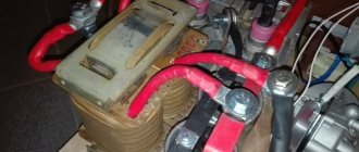
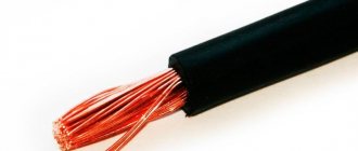
Externally, the inverter consists of a power source, ground cables and a holder, and a power cord. Welding is possible due to the conversion of current into direct voltage with a decrease in volts and an increase in amperes, and the closure of an arc with a temperature of up to 5000 degrees on the product, which melts the edges of the metal and the electrode. Protection from the effects of the atmosphere on the liquid metal is achieved by covering the electrode, which forms an insulating gas cloud.
The inverter housing is equipped with an indication of sensor operation, a current and voltage regulator, sockets for connecting cables, a belt and a transport handle. Perforations for ventilation are required. Visual control of current strength is available using the scale and switch position or digital display.
Inside, the welding inverter consists of the following parts:
1. Filter capacitors. 2. Pulse width modulator. 3. Regulator.
4. Network indicator and overheat indicator. 5. Cooling cooler. 6. Transistor cooling radiators
7. Step-down transformer. 8. Output rectifier radiator. 9. Output connectors.
In addition, not indicated on the diagram, but each inverter uses:
- interference filters;
- soft start relay;
- current sensors;
- control circuit with keys;
- integral stabilizer;
- diode bridge;
- network rectifier.
The operating principle of the inverter is to receive alternating current from a 220 V/50 Hz network and convert it to direct current. Then it changes back to alternating, but with a frequency of 50-85 kHz. The resulting voltage is reduced at the transformer to 30-90 V, and the current, on the contrary, increases to 20-500 A. At the output, the voltage is rectified again and welding is carried out at direct current with multi-thousandth pulsation.
This scheme made it possible to reduce the size of the transformer and significantly reduce the weight of the device. The arc has become much more stable, softer, and the molten metal is easier to form and form into a seam. Many welders note a pleasant rustling sound when the arc burns, indicating the correct operation of the inverter.
Other advantages of inverters include:
- Economical voltage consumption, reducing the cost of manufacturing structures or home use.
- Low load on wiring, because the power of most devices is in the range of 4-7 kW.
- Supports a wide amperage range for welding thin and thick metals.
- Duration of operating cycle with efficiency up to 95%.
- The ability to weld not only carbon steel, but also alloy metals, as well as copper and aluminum.
- Reduced spatter during welding.
But devices with inverter technology are much more expensive than transformers. Due to their complex electronic circuitry, they require more careful handling and are sensitive to negative temperatures. They are more complex and expensive to repair.
What is the influence of welding current?
This value determines the amount of heat released: Q=(I^2)*R,
We recommend reading: Welding a sauna stove yourself at home
Where:
I – amperage;
R – arc resistance.
Thus, the depth of metal melting depends on this parameter. If you choose it too low, the seam will be weak and there will be uncooked areas.
Excessive amperage leads to through burning of the workpiece with subsequent leakage of metal from the weld pool.
Tips for welding thin metal with an electrode
So, let's look at the technique of welding thin metal in practice and give a number of useful tips from real welders. We use an RDS inverter welding machine with direct current and set the current strength according to the values given in our table. To prevent the sheet structure from moving, we recommend securing it with clamps. Edge cutting when welding thin iron up to 4 mm is not performed.
Place the sides of the parts to be joined as close to each other as possible. There is no need for a gap here. If an overlapping connection is structurally permissible, use this - there will be no burns or the roller falling down.
Next, follow our recommendations:
- Light the arc on the rough workpiece and only then start welding. This way you won’t have to knock on the product, and there will be no traces of arc contact on the front side of the structure.
- Keep the arc not strictly in the center of the joint, but on one side of the workpiece. This will help avoid burn-through at the very beginning of work.
- Move the electrode quickly with minimal lateral oscillatory movements.
- Try to keep the tip of the electrode as close to the surface of the workpiece as possible. The arc will be clearer, the filler metal will be transferred more easily, and there will be normal penetration. But a short arc requires skill (“a trained hand”), so practice on a rough product with a similar cross-section.
- To prevent the metal from falling through on the back side of the seam, use a backing. An iron table will not work - the product will stick. It is best to place a plate of graphite or copper.
- If burns occur despite the minimum welding current, weld the seam with an intermittent arc. We welded 5 mm and removed the tip of the electrode from the weld pool for a second. Then the arc was excited again and 5 mm was welded. This slows down the process, but allows the deposited metal to cool.
- Hold the electrode at an angle of 30-45 degrees. A right angle to the product increases heating and promotes burns.
When the settings of the RDS device do not allow you to reduce the current further, use a ballast rheostat. If the work is one-time and purchasing a ballast is unprofitable, connect a steel spring to the ground circuit, placing it between the clamp and the product. By rearranging the mass clamp along the coils of the spring, you can regulate the current strength due to resistance.
To minimize thermal deformation, follow the welding order of long seams. For example, when welding a large container (shower tank, car fuel tank), start welding from the end of the joint, leading the seam towards you. Boil 8-10 cm at a time and move forward. The new seam ends at the beginning of the previous one. Each short penetration will bend the surface inward, but due to the large number of seams, such “waves” will be barely noticeable than one large deflection of the plane when welding with a continuous seam from left to right.
What does the parameter depend on?
To select the correct current value for welding, it is necessary to take into account a number of factors. To understand their role, each should be considered in detail.
Electrode thickness
The most important criterion. As the diameter of the consumable increases, the amperage increases. The average ratio is 30 A per 1 mm.
The thickness of the electrode affects the amount of current for welding.
On the packaging with consumables, the recommended current is indicated as a range, for example, 80-120 A. The technician selects the exact value experimentally.
Sheet metal thickness
This indicator influences the choice of consumables. As the thickness of the metal increases, the diameter of the rod increases. The amperage increases accordingly. This is because more heat is required to melt the edges of massive workpieces.
The actual size of the part must be taken into account. If the edges were cut, i.e. chamfers were cut from them, then their thickness in the joint area will be less. The current is reduced accordingly.
Seam characteristics
There are 2 welding methods:
- Single pass.
- Multilayer.
The second type is used to connect parts of large thickness. Each layer uses its own consumable diameter and amperage. The root part is boiled with a 3 mm electrode, then thicker rods are used.
The choice of current strength is influenced by the spatial position of the seam. Depending on this, the manufacturer’s recommended value is used:
- Lower – 100% of the manufacturer’s recommended value.
- Vertical – 85-90%.
- Ceiling – 75%.
The choice of current strength is influenced by the position of the seam.
In the latter case, consumables with a diameter of no more than 4 mm are used.
Current polarity
When welding with direct current, there are 2 types of polarity:
1 Direct. The negative pole of the source is connected to the consumable.
2 Reverse. “Minus” is connected to one of the blanks.
The temperature distribution in the arc depends on the polarity. Taking this into account, the amperage is adjusted.
Welding current symbols for electrodes, voltage and polarity
AC and DC current, any polarity
AC and DC current, reverse polarity (positive on electrode)
Alternating and direct current, straight polarity (minus on the electrode)
Direct current, reverse polarity (positive on electrode)
Direct current of any polarity
Universal table for determining current strength
It is convenient to present the dependence of the amperage and diameter of the consumable on the thickness of the workpiece in tabular form. In this case, the relative position of the parts is taken into account.
For butt joints
The surfaces to be welded are located parallel to each other. Set the following amperage:
| Edge thickness, mm | Consumable diameter, mm | Amperage, A |
| 1,5-2,0 | 1,6-2,0 | 30-45 |
| 3 | 3 | 65-100 |
| 4-8 | 4 | 120-200 |
| 9-12 | 4-5 | 150-200 |
| 13-15 | 5 | 160-250 |
| 16-20 | 6-8 | 200-350 |
| Over 20 | 6-8 | 200-350 |
For corner and T-joints
The surfaces of the workpieces are located perpendicularly. The cross section of the surfacing has the form of a right triangle with a convex hypotenuse. The amperage is set in accordance with the table:
| Seam leg, mm | Consumable diameter, mm | Amperage |
| 3 | 3,0 | 65-100 |
| 4-5 | 4,0 | 120-200 |
| 6-9 | 5,0 | 160-250 |
Selecting Electrodes
First of all, we note that for welding thin sheet metal it is important to choose the correct electrode diameter. 4-5 mm rods will create excessive resistance and will not allow the arc to burn normally at low currents. Therefore, when welding thin sheet steel, electrodes with a diameter of 1.6-3 mm are used. The thinner the metal, the smaller the diameter of the rod.
Next, you should pay attention to the characteristics of the electrodes. Let's take for example Barsveld OZS-12 ⌀ 2.0 mm (Premium). They have a rutile coating, which provides:
- easy initial and re-ignition;
- absence of a dielectric tip at the end during attenuation (convenient for reuse after a while);
- beautiful seam;
- light welding on rusty or primed metal;
- low filler metal spatter;
- soft arc burning.
Having purchased OZS-12 ⌀ 2.0 mm (Premium), you will be able to weld thin metal with direct or alternating current in any spatial position. Slag after welding is removed very easily. Good electrodes for working with sheet iron are ANO-21 ⌀ 2.5 mm (Premium), belonging to the E46 type. From the ESAB brand, we recommend ESAB MP-3 electrodes ⌀ 3.0 mm if you are going to weld iron with a cross-section of 1.0-1.5 mm.
The listed electrodes have a rutile coating, so when the arc extinguishes, a “visor” does not form. Consumables with the main type of coating are prone to this effect. The presence of the visor makes it more difficult to re-ignite the arc, since more forceful tapping is required to break the tip of the coating and ensure contact of the conductive rod with the workpiece.
If more than 4 months have passed since the production date of the electrodes, we recommend calcining them first. At home, this can be done in an electric oven, heating it to a temperature of 170-200 degrees. Then excess moisture will be removed from the coating, during welding the arc will not crack much and splash the metal, the seam will be neater.
More information about choosing current for electrode welding in practice
Recommendations from experienced welders will help you find the optimal value.
Influence of welding mode
The parameters that regulate the process are divided into basic and additional. The first group includes:
- speed of movement of the consumable;
- its diameter;
- arc voltage;
- type, polarity and current.
We recommend reading Features of welding mixtures and their use
Arc voltage, polarity and current control the welding process.
Additional options are:
- position of the consumable;
- composition and thickness of its coating;
- part orientation.
All of these factors are called welding mode. They are interconnected: a change in one value entails a correction in the other. For example, if you need to reduce heat input, you can do it in 2 ways:
- Reduce amperage.
- Increase the speed of movement of the consumable.
This relationship is taken into account and, if necessary, productivity is increased. Set the speed to a higher speed while simultaneously increasing the amperage.
It is impossible to evaluate the influence of each factor mathematically and derive the corresponding formulas. In each case, it is important to adapt and select the optimal amperage experimentally.
Arc length
There is a linear relationship between arc length and arc voltage. As the first indicator increases, so does the second. In this case, the current strength and heat generation change little.
Arc length affects voltage.
As the length of the arc increases, the quality of the seam decreases. The reasons are as follows:
- The discharge “walks” along the surface, as a result of which heat spreads over a large area. Accordingly, the edges in the joint zone warm up worse.
- The molten metal from the consumable rod bounces off the poorly heated surface. Spattering increases and the seam becomes dirty. Only part of the alloying elements enters the weld pool.
The optimal arc length in mm is determined by the formula L=d+0.5, where d is the electrode diameter in mm.
The melting consumable is gradually shortened during operation, so the holder is gradually brought closer to the workpiece.
Forward or reverse polarity
When welding with direct current in an arc, 2 zones are distinguished:
- Anode spot. Located on the positive pole side of the source.
- Cathode. It is located on the minus side.
The zones have different temperatures. When using a consumable electrode, the anode spot is colder than the cathode spot, so to connect thin-walled workpieces proceed as follows:
- “Plus” is connected to the part being welded (straight polarity).
- Set the minimum current from the recommended range.
In the argon arc method, direct polarity is used.
This prevents burning of the workpieces.
To connect thick-walled parts, strong heating is required. For this:
- A “minus” is connected to them (reverse polarity when welding).
- Set the maximum amperage from the proposed range.
This ensures deep penetration, making the connection strong and reliable.
When using a refractory electrode (argon-arc method), an inverse temperature distribution is observed: the anode spot is hotter. This technology provides only direct polarity, since in reverse the arc hits the consumable and it quickly becomes clogged. When connecting thin-walled parts, heat input is controlled by amperage and welding speed.
Electrode coating
Based on their composition, there are 4 types of coating:
- Rutile.
- Main.
- Cellulose.
- Sour.
The electrode coating can be rutile.
The main coating differs from the others in the presence of a deionizing element - fluorine. It reduces the number of charge carriers, which makes arcing more difficult. To stabilize this process, it is necessary to increase the amperage by 20-30 A. So, if for welding with a rutile consumable with a diameter of 2 mm, the device is set to 40-70 A, then for the main consumable of the same thickness - to 60-100 A.
Direct and alternating current
The type of current does not affect the amperage. It is selected according to the following criteria:
- If high demands are placed on the quality and strength of the seam, constant tension is used. It is characterized by slight arc deflection and weak metal spattering. The seam turns out smooth and clean. On direct current, the arc burns better; it is possible to regulate the temperature distribution by changing the polarity. This is used when working with thin-walled workpieces and non-ferrous metals.
- If the requirements for the quality and strength of the connection are low, alternating voltage is used. It allows you to reduce costs, because equipment for this type of welding costs 1.5 times less. It is also smaller in size and weight.
We recommend reading: Everything about the welding profession
In addition, preference is given to alternating current in the following cases:
- The workpiece material contains oxides. Frequent changes in the direction of current contribute to their greater destruction. For example, aluminum is welded using alternating voltage, because an oxide film forms on its surface.
- The surface of the part is so dirty that it cannot be cleaned.
With constant current, the seam is smooth.
When choosing the type of voltage, the coating material of the consumable is also taken into account. On electrodes with a basic coating, the arc burns worse due to the deionizing effect of fluorine, so they can only be welded with direct current. For other varieties, any genus is suitable.
Features for inverters
The main difference between devices of this type is the presence of a special electronic unit that increases the frequency of the mains current to tens of kHz. This gives the following result:
- The size and weight of the transformer are reduced.
- Its efficiency increases.
- The price is reduced (due to reduced material consumption).
Electronic control makes it easy to adjust the current strength. It is set by a switch on the inverter, and the device selects the voltage automatically. Models with smooth adjustment are the most convenient to use.
The electronics independently adjusts the amperage when:
- Arc ignition. The function is called “Hot Start” or Hot Start. The current briefly increases by 5-100% of the rated current, which facilitates the occurrence of an arc discharge. On cheap models, the manufacturer sets the excess value at its discretion, and it cannot be changed. On expensive ones, the parameter is set by the user. The function is in demand when welding with poor consumables, the presence of rust and scale on parts, and unstable voltage in the network.
- Breaking the arc or connecting the electrode to the workpiece using a drop of molten metal (the consumable is welded). A surge of current also occurs. This promotes the resumption of discharge combustion or the separation of a drop from the rod. The function is called Arc Force.
- Touching the workpiece with the rod. The amperage is reset, which allows you to tear off the consumable. The name of the function is “Antistick”.
The required mode for welding with an inverter is selected taking into account its power. Many models belong to the household class and are not designed for high currents. The maximum diameter of the consumable for them often does not exceed 2 mm, the recommended amperage is 30-45 A.
What nuances should you consider when choosing an inverter?
Immediately you need to make a reservation and say that it is better to choose an inverter with some reserve in terms of current strength.
There are a couple of good reasons for this, namely:
- Firstly, an inverter with a current reserve can be used more flexibly in the future. What if I have to cook with 5 mm electrodes? Then it is necessary that the inverter be at least 250 Amperes;
- Secondly, not all inverters are capable of delivering maximum current. Some models, even if the passport says 200 Amperes, are never able to give 100%;
- Thirdly, the network may have low voltage, and then the inverter power will not be enough.
It is also recommended to look at the exact purpose for which the welding inverter will be used. If its use is limited only to home work, then a device with 160-200 Amps will be more than enough. Why pay extra for unnecessary amps if you never have to use them?
However, you should not choose the cheapest welding inverters in price. The best inverters in Russia today are: Resanta, Svarog, Fubag. Inverters from these manufacturers are distinguished by good build quality, high performance, and operational reliability.
Does the electrode brand affect the choice of current strength?
The composition of the coating is determined by the brand. For example, Uoni-13 and TsU-5 consumables have a basic type of coating. They provide high quality and strength of the weld due to the absence of hydrogen in the metal, but burn worse than others. Therefore, they are welded only at constant voltage, the amperage is increased by 20-30 A. Other consumables are not so demanding on the welding mode.
Recommended parameters for all products are indicated on the packaging.
Knowing how to select the welding current, the master will perform the job efficiently with any electrode and in all spatial positions.
Polarity forward and reverse: what is the difference
Polarity in welding on an inverter machine is an extremely important thing that you need to understand.
If the welding current is constant, then the movement of electrons is also constant. And in this situation, there is almost no splashing of drops and pieces of molten metal, as a result of which the seam comes out neat and of high quality.
At its core, polarity is the direction of electron flow, which depends on the order in which the cables are connected to two different connectors on the device. Inverters have the ability to select the type of polarity. The welding current can also be adjusted.
Reverse polarity
Types of polarity for welding.
This is the negative pole on the metal workpiece, and the positive pole on the electrode. The current thus moves from minus to plus, that is, from the metal to the electrode. With this method, the electrode gets quite hot. The method is good when welding thin metals as the risk of burn-through is reduced.
Straight polarity
Here it’s the other way around: the negative pole is on the electrode, and the positive pole is on the metal of the workpiece. The current now flows from the electrode to the part being welded, which in this case heats up more than the electrode. This is how they work with thick metal edges.
It should be noted that the polarity is always indicated in the instructions on the packs of electrodes.
One of the main “inverter” questions from debutants is what is the most optimal polarity when welding with an inverter? The answer depends on many criteria, but from the point of view of cutting metal, the polarity should be straight.
The fact is that with this type of polarity, the molten area turns out to be deep and narrow - just what is needed when cutting.
With reverse polarity, the opposite is true: the melting zone is shallow and quite wide.
Determining the characteristics
Choosing a price category is good, but you also need to select technical specifications. First, let's decide on the power supply. If you are choosing a unit for private use at home or in the country, most likely you will be more satisfied with power from a 220 V network. There are also welding inverters from 380 V, but it is unlikely that anyone has such sources at home. And if there is one, choose three-phase inverters. There are much fewer of them, but they also exist.
Welding current
How to choose a welding inverter based on technical characteristics? In this matter, they proceed from the products and their thickness that you plan to work with. First of all, select the maximum welding current that the unit can produce. It is designated Imax, the unit of measurement is Amperes.
There is a fairly clear relationship between the thickness of the metal you want to work with and the current that will be needed for welding. This dependence is presented in the table.
Yandex.RTB RA-1479455-7
| Diameter of electrodes, mm | Metal thickness, mm | Welding current, Amps |
| 1.5 mm | 1.2 - 2.0 mm | 30 - 75 A |
| 2.0 mm | 1.5 - 3.0 mm | 40 - 100 A |
| 2.5 mm | 1.5 - 5.0 mm | 50 - 120 A |
| 3.0 mm | 2.0 - 12.0 mm | 100 - 150 A |
| 4.0 mm | 4.0 - 20, mm | 120 - 200 A |
| 5.0 mm | 10 - 40 mm | 170 - 270 A |
If you are going to weld ferrous metal (angles, channels, etc.) with a thickness of no more than 1 cm, it is enough for you that the inverter can produce 160-180 Amperes. If, at least from time to time, you have to work with greater thickness, you need a current of up to 200 Amps. Sheets of iron thicker than 2 cm are not used anywhere in everyday life, so 220-250 Amps for a home or cottage is clearly too much. It’s hardly worth overpaying for unnecessary power; then it’s better to spend the money on purchasing a unit of a higher class (or on a good chameleon mask, without which it will be difficult for a novice welder).
In addition to the welding inverter, you will also need protective gloves and a welder’s mask
Yandex.RTB RA-1479455-3
The minimum current Imin is needed when welding thin metals with an inverter. If you need to weld steel or stainless steel up to 2 mm thick, you will need to heat the parts being welded as little as possible. This is where the minimum current is needed. As a rule, the lower limit of adjustment is 10 A, but there are units on which you cannot set it to less than 30-40 A. They are good for those cases if you have special equipment for “delicate” operations (for example, a semi-automatic welding machine).
The organization of current regulation is also important. It can be stepped or smooth. Continuous adjustment is better - it allows you to more accurately select the operating mode for each metal and electrode.
Open circuit voltage
This characteristic is measured with the equipment turned on and no load. Denoted as Uxx, the unit of measurement is Volts (V). It determines how easily the welding arc will be ignited and how stable the arc will be. The range of values is 40-90 V. The higher the declared open circuit voltage, the easier the welding will be.
Technical characteristics of the welding inverter Fubag in 160
Supply voltage
As already mentioned, most inverters operate from a 220 V network. But on Russian networks, a more or less stable voltage is maintained only in large cities. In rural areas, a voltage of 190 V is already good. But the good thing about inverter welding machines is that they are undemanding in terms of supply voltage. They cook quietly at 180-190 V, and some models can “pull” an electrode with a 3 mm diameter even at 150 V.
If the voltage in your village is low, pay attention to this indicator. It is usually written simply as “voltage” and the minimum and maximum values are indicated through a dash: for example, 150-245 V. Sometimes you can see the following entry: 220 V +10%, -30%. This means that the device will cook normally if the supply voltage is in the range from 154 V to 244 V (220 V - 30% = 154 V, and 220 V + 10% = 244 V).
Maximum current operating mode
If you have to work at the maximum possible current, then the unit will have to be given time to cool down. That is, cook for a while, rest for a while. These intervals are counted for 10 minutes, designated in the technical data as “DC at maximum current”, measured as a percentage - %.
For example, if the characteristic specifies the PV at a maximum current of 40%, this means that out of 10 minutes you can cook 4, and 6 you will wait until the device cools down. At least 50-60% are considered normal characteristics, 70% and above are considered good.
Yandex.RTB RA-1479455-8 Technical characteristics of inverter welding TORUS-165 MASTER (Torus 165 Master)
Please note that this requirement only applies to the maximum current, or close to it. At medium or low currents there is no need for forced stops. You will still have to change the electrodes or position or move the part from time to time. So there will be pauses.
That's all the technical parameters that are needed. Now you know how to choose a welding inverter based on its characteristics. But that's not all. There are also additional functions. For beginners they can be very useful. And some operational issues may also influence the choice.