Converting one type of current to another is required quite often. The method of converting AC into DC is simple: a diode bridge and a smoothing capacitor are used.
But not everyone knows how to turn direct current into alternating current. Meanwhile, in the field of electrical engineering, such a transformation, as will be shown below, is also performed quite often.
DC/DC converters
They are also called DC/DC converters. They are used in computer equipment, communications, control and automation circuits. They provide a decrease or increase in voltage from the power source (for example, batteries or galvanic cells) to the value required to power the load. Some models can also invert the signal to produce a voltage with reverse polarity. The electrical circuit of converters usually includes elements such as an input filter, a capacitor, inductors, a switching transistor or thyristor, and a diode. The key is controlled using PWM. Below is a functional diagram of a boost converter.
The DC/DC converters category includes high-voltage converters. They are used for low current loads that do not require significant power supply power. These include, for example, radiation counters, air ionizers, and cathode ray tube anodes in oscilloscopes.
Most modern DS/DS converters have galvanic isolation. In such devices, the input and output electrical circuits are separated by an insulating barrier. This solution allows you to protect people and the connected load from an emergency increase in voltage at the input, and also improves the noise immunity of the converter.
Methods for generating electricity
Today it is impossible to imagine your life without electricity. Every day, the entire population of our planet uses millions of watts of electricity to ensure normal life. But once again, when turning on the electric kettle, a person does not think about what path the electricity had to travel so that he could brew himself a morning cup of aromatic coffee.
There are several ways to generate electricity:
- from thermal energy;
- from the energy of water;
- from atomic (nuclear) energy;
- from wind energy;
- from solar energy, etc.
In order to understand the nature of the occurrence of electrical energy, let's consider several examples.
AC/DC converters (rectifiers)
AC/DC converters are used to convert alternating voltage (for example, standard voltage of household or industrial electrical networks 220/380 V) into stabilized direct voltage. The devices are widely used in industrial automation, the manufacture of power supplies, telecommunications, transport, electroplating, power plants, and welding machines. Depending on the power switches used, rectifiers are:
1. Thyristor. They usually consist of the following main components:
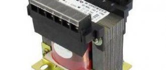
- transformer. Necessary for lowering/increasing voltage, as well as galvanic isolation of the rectifier from the mains;
- thyristor bridge (valve group). Designed to convert alternating current into direct current and regulate (stabilize) the parameters of the rectified current, regardless of voltage fluctuations at the input;
- valve group control unit;
- capacitive, inductive or combined filter (LC filter). Designed to smooth out ripples in output parameters.
2. Transistor. These rectifiers include the following elements:
- input LC filter. Necessary to protect the supply network from interference created by the rectifier;
- diode bridge;
- RF converter. Designed to convert direct current into high-frequency pulsed current and regulate (stabilize) the parameters of the rectified current, regardless of fluctuations in the input voltage;
- HF transformer. Designed to lower/increase the voltage of pulsed current;
- diode or transistor rectifier bridge. Designed to convert high-frequency pulsed current into direct current;
- Control block;
- output LC filter.
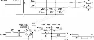
DC to AC converters
These devices are called DC/AC inverters. They can be used as separate equipment or be part of uninterruptible power supplies and power conversion systems. The generation of alternating voltage is carried out using transistors and PWM. Periodic high-frequency opening/closing of transistors in an electrical circuit ensures a change in the direction of current flow and a sinusoid is obtained.
It is important not only how the voltage inverter works, but also what topology for generating a sinusoidal signal it uses. There are two main options:
Half-bridge topology with through neutral. It is distinguished by a minimal number of power transistors and a fairly simple circuit. The disadvantages include the need to use a bipolar power supply and a doubled number of high-voltage capacitors. This option is usually used for not very powerful loads (0.5-1 kW).
Bridge topology. The most common circuit in power converters. It is characterized by increased reliability, does not require large input capacitance, and ensures minimal ripple on transistors. Disadvantages include increased driver complexity and an increased number of transistors.
How the device works
Imagine being a DC battery and someone taps you on the shoulder and asks you to produce an AC battery instead. How would you do it? If all the current you produce flows in one direction, how about adding a simple switch to your output? Turning your current on and off can very quickly provide DC pulses that could do at least half the work. To make a proper AC , you will need a switch that allows you to completely cancel the current and do this about 50-60 times per second. Visualize yourself as a human battery, changing contacts back and forth more than 3,000 times per minute.
Essentially, an old-fashioned mechanical inverter boils down to a switching box connected to a transformer. And since electromagnetic devices that change low-voltage alternating current to high-voltage current or vice versa, using two coils of wire (called primary and secondary) wound around a common iron core.
In a mechanical inverter , either an electric motor or some other automatic switching mechanism reverses the incoming current back and forth basically simply by changing the contacts and generates an AC in secondary mode. The switching device works in the same way as in an electric doorbell. When power is connected, it magnetizes the switch, pulls it out, and turns it off very quickly. The spring will push the switch back, turning it on, and then repeat the process over and over again.
The switching frequency is set by control signals generated by the control circuit (controller). The controller can also solve additional tasks:
- Voltage regulation.
- Synchronization of key switching frequency.
- Protecting them from overloads.
Selection criteria and calculation of a voltage inverter
The most important characteristics of the inverter:
- voltage converter frequency and voltage shape. It is advisable to purchase a device that produces a pure sinusoidal signal. Even highly sensitive equipment can be connected to such a converter;
- rated power. It must be higher than the total load of all connected consumers;
- maximum peak power. This value determines the maximum load the device will withstand when connecting equipment with a low cos f value. Such equipment includes electric motors, pumps, compressors;
- value of input/output voltage and electric current.
To calculate the required power of a DC/AC converter, you must:
- Add up the power consumed by the connected equipment. It is taken from the passport data for the equipment. For example, a refrigerator - 200 W, a washing machine - 1500 W, a vacuum cleaner - 1000 W. Total in total: 200 + 1500 + 1000 = 2700 W.
- Consider peak load. To do this, we multiply the resulting amount by a factor of 1.3 (for the example under consideration: 2700 * 1.3 = 3510 W).
- Take into account the coefficient cos f to obtain the result in volt-amperes. Its value for different equipment varies within 0.60...0.99. For calculation it is better to take the minimum value. 3510/0.6 = 5850 VA ≈ 6 kVA. It is this value that you should focus on when choosing an inverter.
Inverters with built-in solar controller
Now let's see how correctly it is to integrate a solar controller inside the inverter. In general, a solar controller is necessary so that solar panels (some call them solar panels) can be connected to batteries, the same ones to which the inverter is connected. The solar controller converts energy from the high voltage of the solar panels to the lower voltage of the batteries. There are not many such inverters with a built-in solar controller. But this solution has advantages - after all, the price of such a solution is somewhat lower and, in addition, there will be slightly fewer connection wires. Now let's look at the disadvantages of this solution. High-quality and powerful solar controllers (with 98% efficiency, high input voltage and control of external loads) are quite large and cannot be inserted inside the inverter. Look at the disassembled solar controller IES Dominator 200/100.
Therefore, charge controllers built into inverters, like built-in stabilizers, are somewhat limited in their capabilities.
Compare in the photo an inverter with a built-in solar controller (left) and two full-fledged separate solar controllers. A separate controller is almost half the size of an inverter. The difference in functionality and parameters is also noticeable.
Another disadvantage is that if the solar controller is damaged, you will have to send the entire device for repair, i.e. lose the inverter. Just like in the case of damage to the inverter, you will also lose the controller.
In general, the most expensive and high-quality branded inverters never contain either stabilizers or solar controllers. Therefore, their very presence in the inverter indicates the level of the product. It says that for the sake of advertising the presence of ephemeral advantages or a seemingly lower price (based on the sum of supposedly two products in one), the manufacturer is ready to make some kind of compromise with real expediency. This is especially true for the built-in stabilizer. Our advice is to purchase inverters with a built-in stabilizer or with a built-in solar controller if you are short on money, and provided that they are not used in complete autonomy, but as a backup system.