What is portable grounding and its purpose
Portable grounding (PG) is a special product designed for grounding individual sections of an electrical installation that do not have stationary grounding blades. The main function of the PP is to ensure the safety of workers when carrying out repair work.
This is what portable grounding looks like
Installing a PZ allows you to protect personnel from exposure to electric current due to erroneous, spontaneous supply of voltage, as well as as a result of the formation of induced voltage. When voltage is applied to a grounded section of the electrical network, a short circuit current is generated, which leads to the launch of protection, followed by disconnection of the voltage source.
Artificial grounding
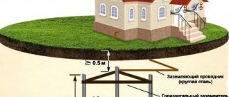
The main element of such a system is a specially designed and manufactured circuit. It consists of several metal conductors placed in the ground. As a rule, rods, angles, pipes or other metal products are used for this purpose. Their length must be at least 2.5 m. The main purpose of this design is to dissipate the current inside the soil in order to avoid injury to humans. The material from which the grounding loop is made must match the resistance of the soil in which it is installed, and also take into account the climate characteristics (primarily humidity and precipitation levels). It is strictly prohibited to coat the circuit with anti-corrosion compounds, as this may impair its conductivity and, therefore, reduce the efficiency of the device.
A conductor is connected to the ground electrode, which ensures the transmission of current from the electrical installation to the ground loop, creating a closed electrical circuit and protecting people from injury. The only requirement for the conductor is resistance to external influences and strength. As a rule, it is made of steel.
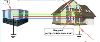
The conductor is connected to a shield, which ensures the distribution of current through the wiring in the room. Modern standards provide for wiring in rooms where people are located using three-core wires. One of the conductors is a phase (it supplies electricity to the electrical installation), the second is a zero (it is without voltage and connects the phase to the ground wire), and the third closes the circuit, directing the current to the ground. When the device is plugged into an outlet, the grounding wire automatically begins to operate, providing protection.
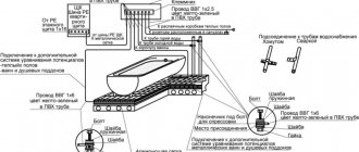
Protective grounding device
If suddenly, due to wear and tear of the insulation, current instead of a phase begins to flow into the body of the device, the protective wire leads it to the ground, which eliminates the possibility of injury. If a short circuit occurs due to insulation problems, the circuit breaker will operate and cut off the electrical current. In any case, the current will pass through the protective conductor and dissipate in the ground.
So, answering the question why grounding is needed, it should be noted that its main function is to protect against injury during the operation of electrical appliances and equipment. This is achieved by installing a special circuit in the ground and laying wiring from three-core wires.
Device
There are two main options for using PP. The first option is intended for use in switchgears, and the second - on overhead power lines. Grounding can be made in single-phase or three-phase design.
The PZ can be made in three design variations: rod, rod with a metal link (ZPL-10) and rodless (ZPP-15).
Portable grounding type ZLP-10
The design of the product consists of the following elements:
- flexible conductor (copper or aluminum);
- fastening clips;
- tips (clamps);
- dielectric rod.
The rodless design of the PZ is usually used for use in complete switchgears.
Example of a rodless PZ design
To simultaneously short-circuit three phases through a single grounding conductor, a three-phase grounding conductor is used.
Single-phase version of portable grounding is intended for separate connection of phases to the grounding loop. Used on power lines with a voltage level of more than 110 kV. This is due to the significant distance from the grounding bus to the phase wires and the phase-to-phase span.
The flexible conductor may be coated with transparent insulation. It can be made of aluminum or copper wires. Using clamps, the PZ is attached to live parts and to the ground loop. The device of phase clamps can be made in the form of clamps and copper tips. The clamps are tightened using an insulating rod, with the help of which the minimum permissible distance to live parts is achieved.
How does grounding work?
First, let's figure out why dangerous voltage appeared on the body of the washing machine or other electrical equipment. Everything is quite simple - the insulation of the conductors for some reason has deteriorated or been damaged and the damaged area touches the metal casing of some equipment part.
If you do not have a ground or ground connection, the case of the damaged device for the electrical circuit is nothing until you touch it, of course. You approach the device, stand on the floor, the floor has, although weak, some contact with the ground. When you touch the body, current begins to flow through you into the ground. For current to flow, a potential difference is needed, and the potential of the phase wire is always greater than the ground potential. It turns out that you are shorting the phase wire to the ground with your body.
Even such small values as 50 mA are dangerous for humans - such a current can lead to ventricular fibrillation and death.
Requirements
There are many requirements for portable grounding systems. Among the main ones, thermal and dynamic stability with respect to short circuit currents stands out. The design of products should ensure ease of use.
The shorting conductors must withstand environmental influences ranging from -45 to +45 degrees. The cross-sections of the grounding conductors must correspond to the voltage levels. In electrical installations up to 1 kV, 16 square millimeters are used, and at voltages above 1 kV - 25. At a voltage level of more than six kilovolts, the cross-section of the conductors can reach one hundred and twenty square millimeters.
If there are different voltage levels in electrical installations, it is permitted to use portable grounding with the largest required cross-section to service all electrical equipment.
The product package must include technical documentation. The clamp can be fastened to the conductor cores by bolting, welding, pressing or using pressure plates. The clamp must ensure reliable contact at the application site. Insulating structures must be made of dielectric materials.
It is prohibited to use protective shells on conductive elements of the ground electrode, which interfere with visual inspection of their integrity. To insulate wires, it is allowed to use only a transparent sheath.
Calculation of cross-section for PZ
The minimum cross-section of the grounding conductor is determined by the formula:
Smin = (Ik.z.*√t)/C
- I short circuit – maximum current value during a short circuit;
- √t – the longest response time of the main protective devices to disconnect a short circuit;
- C is the calculated coefficient, which reflects the change in the resistance of the material under the influence of heat.
The longest time to disconnect a short circuit is taken to be the total value of the following indicators:
- activation time of the main protection;
- response time of automatic restart (reclose);
- duration of machine shutdown.
The calculated value of I short circuit depends on the type of neutral of the electrical network. With a grounded neutral, the value of single-phase short circuit current is used, with an isolated neutral - three-phase.
Installation and removal of portable grounding
The process of applying and removing grounding is identical for all voltage levels. There are differences only in the number of people performing these operations. In electrical installations up to 1 kV, installation and removal of the ground electrode is carried out individually, and at voltages above 1 kV, the procedure is performed by two people. One person acts as a controller, and the second is an executor.
Process of installation and installation of PZ
Sequence of actions when installing the software:
- Make sure the integrity of the installed grounding;
- Check that there is no voltage at the electrical installation that must be grounded;
- Connect the clamp PZ to the ground loop;
- Place grounding conductors on current-carrying elements.
Operations for removing portable grounding are carried out in the reverse order. All actions must be carried out using dielectric gloves and rods, as well as personal protective equipment. In electrical installations up to 1 kV, only insulating gloves may be used. When the voltage of current-carrying elements is more than 1000 V, the simultaneous use of gloves and rods is required.
Checking the absence of voltage in a section of the distribution installation is carried out with a voltage indicator.
Parallel installation of portable ground electrodes in an electrical network with a voltage of more than six thousand volts is allowed. This is due to the fact that the required wire cross-sections reach significant values. And it leads to an increase in the mass and size of the PZ, which entails difficulties in their operation.
Grounding principle
Once the devices are grounded, we are not afraid of breakdown of internal insulation. If for some reason the device body is energized, a short circuit will occur between the phase and ground. As a result, the circuit breaker will trip. Thanks to correctly installed grounding and operation of the machine, a person will not be shocked.
However, there are some nuances of electrical engineering. It is not always the case that a voltage breakdown can knock out a machine, and in such cases a residual current device will be an excellent assistant.
| I would also like to note the fact that with high-quality installation of the grounding circuit, its resistance should be 4 Ohms, and if for some reason there is a delay in turning off the machine or it does not turn off at all, the potential on the body of the damaged device will be equal to the potential of the ground electrode. In this case, a person will not receive an electric shock when touched, since there is no potential difference. |
Tests
To confirm compliance with GOST requirements, portable grounding systems are subjected to the following types of tests:
- acceptance (during the initial check for compliance with established standards);
- periodic (permissible once every five years);
- standard (with design changes).
Portable groundings are considered suitable for use if the following measures are successfully completed:
1. Visual inspection of the integrity of all structural elements.
Includes inspection of clamps, conductor cores, insulating rod, restrictive ring on the rod, anti-corrosion coating, protective insulation and technical documentation.
2. Climatic tests.
The procedure is carried out at negative and positive temperatures. Its value should reach forty-five degrees Celsius, respectively, below and above zero. Portable grounding is exposed to temperature for two hours. If there are no signs of destruction of the protective insulation and plastic elements, the product is considered suitable for use.
3. Determination of the mechanical strength of rods.
This experiment is intended to measure the bending of the PZ rod. The permissible deflection deviation is ten percent relative to the insulating length of the rod used for electrical installations with voltages up to 220 kV. For higher voltage levels, a twenty percent deviation is allowed.
To carry out the test, the rod is fixed in a horizontal plane. Securing the end of the rod and the place where the restrictive ring fits. Use a metal ruler to set the level of the rod axis. And according to it, the amount of deflection is calculated.
4. Checking the cross-section of the cores.
To establish the actual cross-section of the portable grounding, it is disassembled into strands. Their number is recorded and the number of conductors in one strand is counted. The diameter of the conductor is measured to determine its cross-section. The resulting calculated value is multiplied by the number of conductors in the strand and by the number of strands.
5. Measurement of thermal and dynamic resistance.
The experiment consists of passing through the finished product the appropriate value of short circuit current from laboratory current sources. The current flow continues until the prototype is completely destroyed. If within three seconds no mechanical damage or cores being thrown from the installation sites were observed, then the sample satisfies thermal and dynamic resistance.
6. Determination of the level of contact resistance.
A microohmmeter is used to measure the resistance at the point where the conductors are connected to the clamp. This indicator should not exceed 600 μOhm.
7. Electrical checks of insulating elements.
The insulating parts of portable grounding are subjected to high-voltage tests.
During operation, mechanical tests of grounding wires are not performed. Rods with metal elements are subject to electrical testing. This procedure is performed every two years.
The product is removed from service if the following defects are found:
- disruption of the connection between the clamp and the conductor;
- traces of metal melting or destruction of grounding conductors;
- the presence of more than five percent breakage of conductor cores.
How does grounding work?
Why grounding is necessary and the principle of its operation is something that even a home craftsman needs to know. Grounding serves as protection against possible electric shock in the event of an insulation breakdown, after which voltage is supplied to the body of metal household devices. If the grounding is designed correctly, the current will be directed into the ground and will not hit the user when touched.
If a special device is built into the power supply system that turns off the network, then in the event of such a voltage leak it will turn off the current supply.
There is not enough knowledge on how to properly make grounding in a country house and in a private house; you still need to comply with all the parameters when designing. In another situation, the circuit will have greater resistance and will not be able to perform the protection function.
The grounding loop is a structure made of metal pins and busbars, which is located in the ground and, in the event of an insulation breakdown, discharges voltage into the ground. Not any type of soil accepts current. Therefore, it is advisable to carry out grounding arrangement on certain types of soil.
Ideal for grounding:
- black soil;
- loamy and clayey soil;
Note that grounding must be arranged below the soil freezing mark. Otherwise, in winter, the device will perform its functions only partially. When designing, it should be taken into account that the grounding loop should be located at a distance of 1-10 meters from the residential building; to drain it to a certain distance, it is necessary to dig a trench and lay the loop.
The circuit is:
- triangular;
- rectangular;
- oval;
- linear and arc.
To design grounding, it is better to choose a triangular type of circuit, but there are other options.
Triangle
Knowing how to make grounding in a private home and country house, home specialists give preference to triangular options. The reason for choosing this particular option is that with small dimensions of the product, the current is dissipated on different sides; we also note that the design costs are minimal and the circuit complies with all standards.
When constructing an isosceles triangular contour, the minimum length of the sides is equal to the length of the segments, and the maximum can be achieved by connecting several pieces of metal.
It is not always possible to dig a hole to form an equilateral triangle, as stones may be encountered or the soil may be difficult to till. In such situations, the parties need to be shifted, the principle of operation and effectiveness will not change.
Linear
Some find it much easier to organize a linear ground loop. The design of such a circuit involves a linear connection of pins using electrodes. The gap between the pins in this case is also equal to the length of the electrodes. When organizing such a circuit, more pins will be needed, since it is necessary to achieve greater voltage dissipation. But since horizontal electrodes take a long time to hammer in and there are a lot of them, if possible, triangular contours are preferred.
Equipment and markings
Depending on the design of the product, the kit includes:
- portable grounding, assembled or disassembled;
- insulating rods;
- covers;
- technical certificate.
All portable grounding connections must be marked. Which reflects the following information:
- trademark or name of the enterprise that produced the PZ;
- release date and product type;
- core section;
- operating voltage level.