An induction motor is the most efficient machine for converting electrical energy into mechanical energy. Invented more than a hundred years ago, the electric motor still remains relevant, and the principle of its operation has remained virtually unchanged.
1888 Italian electrical engineer Galileo Ferraris publishes an article addressed to the Royal Academy of Sciences in Turin, where he asks for attention to his research, as a result of which the inventor was able to obtain the first theoretical basis for the operation of an asynchronous motor. At the same time, in the USA, Nikola Tesla received a patent based on the same information.
Mikhail Dolivo-Dobrovolsky
Ferraris's main merit is an error in his conclusion about the efficiency of an asynchronous motor. Thinking that the figure was small and the use of alternating current was generally impractical, he was able to gain the attention of many scientists and engineers, who nevertheless took up the issue of improving the electric motor. The article was translated into English and one day Mikhail Dolivo-Dobrovolsky read it. Having become interested in the topic, a German engineer with Russian roots began work on creating a new electric motor. The next two years were marked by truly great inventions. 1889 – Dolivo-Dobrovolsky received a patent for a three-phase asynchronous motor with a squirrel-cage rotor of the “squirrel wheel” type, in 1890 – for a phase rotor. With his inventions, Mikhail Osipovich opened a new era in industrial production. Electric machines made it possible to launch mass production.
Already in 1903, the first elevator in history was built in the city of Novorossiysk, which was equipped with a three-phase alternating current network. The equipment process took place under the clear guidance of the inventor himself.
Today, the car invented by Dolivo-Dobrovolsky at the suggestion of Ferraris is the most common type of engine in the world. The scope of application of an asynchronous motor is extremely wide. Three-phase motors are used to drive production equipment.
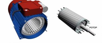
Like any electric motor, an asynchronous motor has two main parts - the rotor and the stator. These are the basic elements for converting electrical energy into mechanical energy.
The stator is the part of the engine that remains stationary. On its inner side there are special grooves where the three-phase winding is laid. It is powered by three-phase current.
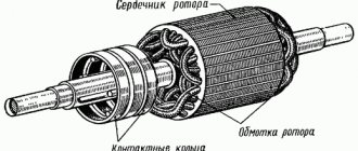
The rotor is the part of the machine that moves during operation. The winding is also placed in its grooves.
Both parts, static and moving, are made of electrical steel. More precisely, from sheets whose thickness ranges from 0.35 mm to 0.5 mm. Each sheet is isolated from the other with a thick varnish coating.
As for the gaps, between the rotor and stator they are kept minimal: for less powerful motors from 0.3 mm to 0.35 mm, and for more powerful machines - from 1 mm to 1.5 mm.
All asynchronous electric motors are divided into two types: with a squirrel-cage rotor and with a phase rotor. From the name it is clear that the fundamental difference between the devices lies in the structure of the rotor itself. Motors with a squirrel cage type of rotor are more popular. The reason for this is simple: their design is somewhat simpler.
Stator winding of an asynchronous motor
The stator winding in such a motor, as mentioned above, is placed in special grooves. It itself is made of several connected coils. The turns that make up the coil are completely insulated.
Stator windings. Picture 1
Figure 1a shows the stator winding in an asynchronous electric motor. All coils have two conductors: the stator is two-pole. A winding of three coils can create a magnetic field and two poles. One period of three-phase current is equal to one revolution of the magnetic field. That is, if the frequency is 50 Hz, then the number of revolutions will be 50 times per second (3000 per minute).
Figure 1b shows a winding with two conductors on each side of the coil. This is a four-pole stator. Its magnetic field rotates twice as slowly as that of a bipolar one. This means that at the same frequency of 50 Hz, the field will make 25 revolutions per second (1500 per minute). A four-pole stator with a winding, where there is one wire per pole and phase, is shown in Figure 1c. In Figure 1d, there are two conductors per pole and phase of the same stator.
If the stator is six-pole, then its speed will be three times less than the speed of the previous one (1000 rpm at a constant frequency of 50 Hz). A six-pole stator, where there is one wiring per pole and phase, is shown in Figure 1e.
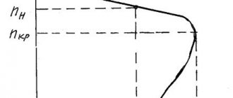
Changing the rotor speed
The parallel windings of two phases form one pair of poles shifted in space by 120 degrees. The series connection of the windings forms two pairs of poles, which makes it possible to reduce the rotation speed by half. To regulate the rotor rotation speed by changing the current frequency, a separate current source or an energy converter with adjustable frequency, made on thyristors, is used.
At the moment of starting, the engine develops quite a significant torque, and since its inertia is relatively small, the rotor rotation frequency quickly increases and is almost equal to the field rotation frequency, so that their relative frequency becomes almost equal to zero and the current in the rotor quickly decreases.
It will be interesting➡ Little-known facts about DC motors
For low- and medium-power motors, short-term overload during startup does not pose a danger, but when starting very powerful motors (tens and hundreds of kilowatts), special starting rheostats are used that weaken the current in the winding; As the rotor reaches normal speed, these rheostats are gradually turned off.
As the engine load increases, the rotor rotation speed decreases slightly, the field rotation frequency relative to the rotor increases, and at the same time the rotor current and the torque developed by the engine increase.
However, to change the engine power from zero to normal, a very small change in rotor speed is required, up to about 6% of the maximum value. Thus, the three-phase asynchronous motor maintains an almost constant rotor speed even with very wide load fluctuations.
It is in principle possible to regulate this frequency, but the corresponding devices are complex and uneconomical and therefore are used very rarely in practice. If machines driven by an engine require a different rotation speed than the engine provides, then they prefer to use gear or belt drives with different gear ratios.
Design of an electric motor with a squirrel-cage rotor
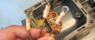
The most popular type of engine, with a squirrel cage rotor, has the following structure (Figure 2). The three-phase winding (2) is placed on the stator (the stationary part of the electric motor) (1). The winding is powered by three-phase current. Each beginning of all phases is displayed on a common panel. It is mounted on the outside of the motor housing.
Asynchronous motor with squirrel-cage rotor. Figure 2
The core of the static part of the unit is assembled and placed inside the housing (3), made of cast iron. Copper rods are placed in the grooves of the movable armature (the second name for the rotor) (4). On each side they are soldered to rings (they are also made of copper) (5).
It turns out that each rod is short-circuited on both sides. If you depict a rotor winding of this type, its appearance resembles a squirrel wheel.
In all engines with a power of no more than 100 kW, such windings are made of aluminum. It is poured under pressure into each rotor slot.
The rotation of the shaft (6) occurs in bearings. The latter, in turn, are secured in special shields (7,8). Bearing shields are secured to the motor housing with bolts. In order for the rotation of the shaft to be transmitted to the machine or machine, a pulley is mounted on one of its ends.
Start
In asynchronous motors with a high moment of inertia, it is necessary to increase the torque while simultaneously limiting the starting currents - motors with wound rotors are used for these purposes. To increase the initial starting torque, a three-phase rheostat is included in the rotor circuit.
At the beginning of the start, it is fully introduced, and the starting current decreases. During operation, the rheostat is completely withdrawn. To start asynchronous motors with a squirrel-cage rotor, three schemes are used: with a reluctance coil, with an autotransformer and with switching from star to delta. The switch connects the reluctance coil and the motor stator in series.
How to start a three-phase asynchronous motor
When the rotor speed approaches the nominal speed, the switch closes, it short-circuits the coil and the stator switches to full mains voltage. During autotransformer starting, as the engine accelerates, the autotransformer is moved to the operating position in which the full mains voltage is supplied to the stator. Starting an asynchronous motor with the stator winding first turned on by star and then switched to delta gives a threefold reduction in current.
If the insulation of the frame and casings of electrical machines and transformers are damaged (breakdown), they become energized relative to the Earth. Touching these machine parts can be dangerous to people under these conditions.
To prevent this danger, at voltages above 150 V relative to the Earth, the frames and casings of electrical machines and transformers should be grounded, that is, reliably connecting them with metal wires or rods to the Earth. This is done according to special rules that must be strictly followed to avoid accidents.
A three-phase motor is adapted to a three-phase network, and a two-phase motor with a phase shift in the second winding either through a capacitor (capacitor motors) or through inductance is better suited to a single-phase network.
Differences in connecting a three-phase asynchronous motor with single or double voltage sometimes lead to failure of the motor - if you do not pay attention to which voltage is upper and lower, you can connect it incorrectly and it will burn out.
Three-phase asynchronous electric motors up to one hundred and thirty-two gauge inclusive are usually available at a voltage of two hundred twenty by three hundred eighty volts, from one hundred and sixtieth gauge - three hundred eighty by six hundred sixty volts, but there may be other options.
When we turn on an unloaded motor, then in the first moments it is equal to or close to zero, the frequency of rotation of the field relative to the rotor is large and induced in the rotor e. d.s. accordingly, it is also large - it is 20 times greater than that e. d.s., which occurs in the rotor when the engine operates at normal power. The current in the rotor is also significantly higher than normal.
You may also be interested in reading about little-known facts about DC motors in our other article.
Wound rotor device
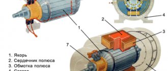
Section of an asynchronous motor with a wound rotor. Figure 4 1 - motor shaft, 2 - rotor, 3 - rotor winding, 4 - stator, 5 - stator winding, 6 - housing, 7 - bearing caps, 8 - fan, 9 - slip rings
A phase rotor is characterized by the presence of three phase windings. They are often connected in a star pattern (sometimes in a triangle pattern). Each end of the phase winding is connected to a copper ring. The rings are fixed on the shaft and insulated. This gave the motor another name: slip ring induction motor. There are three rings in total. They are pressed tightly onto the shaft using insulating gaskets. Brushes are placed on the rings (they are located in the brush holder, in turn mounted on the bearing cover).
The brushes always have good electrical contact with the rings. This connects them to the armature windings themselves. The brushes are connected to each other by a three-phase rheostat.
All asynchronous motors operate on the principle of a rotating magnetic field. But how to create such a field? The easiest way is to rotate a permanent magnet along an axis. You can take a copper disk and spin a magnet around it. If the magnet is strong enough, the copper disk will also begin to rotate, as if trying to keep up with the magnet. It will create the feeling that there is some kind of connection between the two objects that constantly holds them together. The movement of the magnet and the disk will not be synchronous, because the latter will always lag behind in the “chase”.
An explanation for this phenomenon can be given as follows: rotating around a disk, a magnet is able to excite Foucault (induction) currents in it. Their trajectory is a vicious circle. Induction currents have no beginning or end. They can be called short-circuit currents that heat up the metal. As a rule, you need to get rid of them, but in this case they are the reason for the appearance of a magnetic field in the disk. Next, this field begins to interact with the field of the permanent magnet itself.
Asynchronous electric motors work on the same principle, but the rotating field is created not by a magnet, but by the stator winding. In it, in fact, a field suitable for rotation is created.
Such conditions can only be created in a system with several phases, where the current shifts by several degrees. In household electrical appliances, motors usually have two phases, with the second being created artificially. To do this, use a shifting capacitor, coil or resistor. Electric motors used in industrial enterprises are produced with three phases.
The very first three-phase asynchronous electric motor had three windings. They were 120 degrees apart from each other. The operating diagram of such a motor and the sinusoidal current of its three poles are shown in Figure 4.
Figure 4
So, at the moment when the current is zero in one of the phases, in the rest it takes on maximum values, and the phases differ in the direction of the current. This creates a magnetic field between two of the three windings. Then everything immediately changes: one pole is turned off, and the other, the one that remains working, begins to change polarity. This occurs due to a change in the direction of current in the winding. And the pole that has just entered the working state will support the field displacement. Due to this, eddy currents are formed in the armature of the machine (since the magnetic field lines intersect part of the rotor). The currents interact with the stator field, which is already rotating, and try to catch up with it. The rotor rotates.
This principle of operation of an asynchronous machine, which was developed back in the 19th century, is also relevant for those electric motors that are produced today. However, changes in the design did occur. Disc and cylinder armatures have now been replaced with “squirrel cages”; phase-type rotors are more often used. The shape of the winding of the static part of the engine has also undergone changes. Instead of a coil with a pole piece, radial windings are used: they are placed in slots.
It is also worth mentioning what an equivalent circuit of an asynchronous motor is. It is often used in electrical engineering during calculations. Instead of the electric motor itself, an equivalent circuit is substituted, where the electromagnetic connection is replaced by the electrical one.
The supply voltage varies from consumer to consumer, which is why electrical equipment has to be reconnected from time to time. The instructions below will help you safely connect a 220 V electric motor.
The task is quite simple. The main thing in this matter is not to make mistakes when connecting the windings. The engine classification includes two types:
- three-phase with winding (star or delta connection circuit);
- single-phase (it has a starting winding).
We will consider their connection methods.
Operating principle.
When electric current is applied to the stator windings, an electric current occurs in these windings. As you remember from the words written above, our phases are shifted relative to each other by 120 degrees. And this flow in the windings begins to rotate.
And when the stator magnetic flux rotates, an electric current and its own magnetic field appear in the rotor windings. These two magnetic fields begin to interact and cause the rotor of the electric motor to rotate. This is if the rotor is short-circuited.
Based on the robot principle, watch the video clip.
Well, with a wound rotor, the principle is essentially the same. Voltage is supplied to the stator and rotor. Two magnetic fields appear, which begin to interact and rotate the rotor.
Connecting a three-phase motor to the network
A distinctive feature of an asynchronous motor is its simple design compared to other types of electric machines. Its prevalence can also be attributed to its reliability and durability. The AC induction motor has a very simple design compared to other types of electrical machines. It is quite reliable, which explains its popularity. This is connected to alternating voltage using a star or delta circuit. The first scheme is used more often. The operating voltage of electric motors is also different:
- 220–380 V;
- 380–660 V;
- 127–220 V.
So how can you connect the machine without burning the winding?
Required voltage
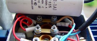
Example of an information plate on an engine
Make sure the motor meets all requirements. They can be found on a label on the outside of the unit housing. It indicates such characteristics as power, voltage for which the unit is designed, and power factor of a particular asynchronous motor. It is important that one of the parameters is voltage 220 V. Then find out the type of connection of the windings. For low voltages, a star circuit is used, and for high voltages, a delta circuit is used.
Connection diagrams
In order to connect a three-phase asynchronous motor, several different circuits are used, but the most commonly used are delta and star.
Triangle
The advantage of this scheme is that when connected according to it, a three-phase motor can develop the highest rated power. To do this, the windings are connected according to the end-to-beginning principle, which in the schematic diagram looks like a triangle, but in the form of a triangle it is not always convenient to understand what’s what. Therefore, we offer for analysis the diagram below, and then the photograph already assembled (even lower).
triangle connection diagram
In three-phase electrical networks, the linear voltage between the terminals of the windings is 380 V. In this case, there is no need to create a working zero. It is important to note that in such a circuit a large inrush current can occur, significantly overloading the wiring.
Star
This connection method is the most used in networks with three-phase current 380 V. The name of the circuit is due to the fact that the ends of the windings are connected at one point, like star rays. The beginnings of the windings are connected via switching equipment to the phase conductors. In such a linear design, the voltage between the beginnings is 380 V, and between the junction and the connection of the conductor - 200 V. Below is a diagram, and even lower is a photograph in assembled form.
star connection diagram
A three-phase motor for 380 V networks connected in this way is not able to develop maximum power due to the fact that the voltage on each winding is 220 V. In turn, this circuit prevents the occurrence of overcurrents, which ensures a smooth start.
The possibility of connecting the motor in one way or another is usually indicated on its plate. The Y symbol means "star" and the ∆ symbol means "triangle". You can determine the circuit on an already connected machine by the type of windings - one double jumper between them indicates that a “star” is used (first photo from the bottom), and if three jumpers are visible between the terminals of the windings - a “triangle” (first photo from the top).
Asynchronous motor, triangle assembly.
Asynchronous motor, star assembly
In the case when it is necessary to start a three-phase asynchronous electric motor in the opposite direction of rotation, the two supply wires from the three-phase source should be swapped.
For high voltage
Let's say the plate has the following data: Δ/Ỵ220/380. This inscription indicates that the motor requires a delta connection. If you have a terminal box, this will not be difficult. The jumpers will simply switch to the required position.
If there is no terminal box and there are only wires in front of you, the entire unit will have to be disassembled. When you get to the stator, you will see three ends of the wires, they will be soldered. You have found a star connection. They need to be disconnected from each other and connected in a triangle pattern.
Overall, it's not very difficult. Remember that a reel has a beginning and an end, do not confuse them. If the beginning is what is brought out into the engine boron, then the ends are soldered.
The connection occurs like this: the end of one coil is soldered to the beginning of the other.
With the help of such simple manipulations, we made a motor designed for a voltage of 380 V, suitable for connecting to a 220 V network.
Connection
The stator windings of a three-phase ADKR can be connected in a “delta” or “star” circuit. In this case, the sprocket requires a higher voltage than the triangle.
Please note that an electric motor connected in different ways to the same network consumes different power. Therefore, you cannot connect an electric motor designed for a star circuit according to the delta principle. But in order to reduce starting currents, you can switch the star-delta contacts during the start-up, but then the starting torque will also decrease.
The connection diagrams are clear from Figure 4.
Rice. 4. Connection diagrams
To connect a three-phase electric motor to a single-phase current, phase-shifting elements are used: capacitors, resistors. For examples of such connections, see Figure 5. You can use either a star or a triangle.
Rice. 5. Examples of connection diagrams for a single-phase network
In order to control the operation of the motor, additional devices are connected to the stator electrical circuit.
For low voltage
It may be that the same tablet says Δ/Ỵ 127/220. This suggests that a “star” winding connection circuit is required. If there is no terminal box, the motor is connected in a triangle, and the ends, as often happens, are not labeled - no problem. There is a solution to the problem. True, in this case everything is somewhat more complicated and will take more time.
Separate all the ends and use an ohmmeter to find the stator coils.
Mark them with tape or colored tape. Perhaps this will come in handy more than once.
Take the battery and connect it to a1-a2. Connect an ohmmeter to b1-b2.
When the contact with the battery is broken, the needle on the ohmmeter will move to the side. Remember exactly where the arrow pointed and connect the device to c1-c2. There is no need to change the polarity. Do it all again.
The arrow may swing in the other direction. In this case, the wires need to be swapped and the markings changed. The arrow should only deviate in one direction.
The battery, on which the polarity is observed, is connected to c1-c2, and the measuring device to a1-a2.
Now everything needs to be rechecked. The needle should deflect equally on all reels. If everything is correct, a bunch with the same numbers (let’s say 1) is the beginning, and a bunch with the number 2 is the end.
All three ends (a2, b2, c2) need to be connected and insulated. This is a star connection. It can be displayed on the terminal block, marked for convenience, or drawn or pasted on a diagram according to which the windings are connected.
Switching from delta to star is ready. The device can be connected to the network.
Connecting single-phase asynchronous motors
Another type of asynchronous electric machines is single-phase AC motors. Such motors have only two windings, and only one works after starting. Such engines have some features, which we will consider.
Such units are also called split-phase electric motors. Their stator has a biased winding (relative to the main one) - it is auxiliary. A phase-shifting capacitor helps start the car.
It is very important to pay attention to the rating plate of the unit. Even if you see three wires, this is not an indication that the motor can be connected to a 380 V network. You risk burning the winding - this is the main malfunction of such motors.
We connect a single-phase motor to the network
First of all, we determine the middle of the coils - this is the connection point. This can be easily done by the color of the wires.
If all ends are brought out normally, then there will be no problems with the connection. If not, then things get a little more complicated.
Try testing the ends of the coils with an ohmmeter. The highest resistance value indicates two coils connected in series. They need to be marked somehow. Let's keep an eye on the device. A starting coil in good condition always has a higher resistance than one that is working. After this, a capacitor is connected.
Done, the single-phase motor can be connected to the network.
It has been said more than once that asynchronous motors are the most common type of electric motors in enterprises. Of all modern equipment, the share of asynchronous units is 95%; the remaining five accommodate more than five types of different electric motors. What are the pros and cons of the equipment and why is it so popular?
Design
Every electric motor has two important working parts: the rotor and the stator. They are enclosed in a protective casing. To cool the winding conductors, a fan is installed on the rotor shaft. This is the general principle of the structure of all types of electric motors.
The designs of the stators of the electric motors under consideration are no different from the structure of these parts in other types of electric motors operating in alternating current networks. The stator cores, designed to operate at three-phase voltage, are arranged in a circle at an angle of 120º. Windings of insulated copper wire of a certain cross-section are installed on them, which are connected by a triangle or star. The design of the stator magnetic circuit is rigidly mounted on the walls of the cylindrical housing.
The structure of the electric motor is clear from Figure 1. Pay attention to the design of the windings without a core in a squirrel-cage rotor.
Rice. 1. Structure of an asynchronous motor with a short-circuit rotor
The rotor is designed a little differently. The design of its winding is very similar to a squirrel cage. It consists of aluminum rods, the ends of which are closed by short-circuiting rings. In high-power motors, you can see the use of copper rods as short-circuited rotor windings. This metal has low resistivity, but is more expensive than aluminum. In addition, copper melts faster, and this is not desirable, since eddy currents can greatly heat the core.
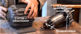
Structurally, the rods are located on top of the rotor cores, which consist of transformer steel. When manufacturing rotors, the cores are mounted on the shaft, and the winding conductors are pressed (poured) into the grooves of the magnetic core. In this case, there is no need to insulate the core grooves. Figure 2 shows a photo of a rotor with short-circuit windings.
Rice. 2. Rotor of an asynchronous motor with short-circuit windings
The magnetic core plates of such rotors do not require varnish insulation of surfaces. They are very simple to manufacture, which reduces the cost of asynchronous electric motors, the share of which is up to 90% of the total number of electric motors.
The rotor rotates asynchronously inside the stator. Minimum distances in the form of air gaps are established between these parts. The optimal gap is between 0.5 mm and 2 mm.
Depending on the number of phases used, asynchronous electric motors can be divided into three types:
- single-phase;
- two-phase;
- three-phase.
They differ in the number and location of stator windings. Models with three-phase windings are characterized by high operating stability at rated load. They have better starting characteristics. Often such electric motors use a simple starting circuit.
Two-phase motors have two stator windings arranged perpendicularly, each receiving alternating current. They are often used in single-phase networks - one winding is connected directly to the phase, and a phase-shifting capacitor is used to power the second. Without this part, the rotation of the asynchronous electric motor shaft will not begin on its own. Due to the fact that the capacitor is an integral part of a two-phase electric motor, such motors are also called capacitor motors.
In the design of a single-phase electric motor, only one working winding is used. To start rotor rotation, a starting inductor is used, which is briefly connected to the network through a capacitor or short-circuited. These low-power motors are used as electric drives for some household appliances.
Positive characteristics of an asynchronous motor
- Often the choice of an asynchronous motor is associated with simplicity of design - this is its main advantage. This explains not only the three-phase electricity supply system, but also the operating principle of the machine. This leads to another positive feature of the electric motor – low price. Of all the types of engines, this one will be the most budget-friendly.
- In order to form a rotating magnetic field in a three-phase electric motor, no additional parts or elements are required. The design of the machine itself causes the rotation of the field in the stator, from which the rotor moves. To do this, you just need to apply voltage using a contactor or starter and the electric motor will start working.
- Diagnostics and maintenance of asynchronous motors are not difficult, and the operating costs of the machine are quite low. If the engine is installed correctly and its operating mode complies with the rules, bearings need to be changed no more than once every 15 years.
Negative points in the operation of asynchronous motors
- The dependence of the rotor rotation speed on how many poles are in the stator winding and on the frequency of the network that powers the motor. If the work involves changing speeds, then this can become a significant disadvantage. To avoid such problems, there is a two-speed asynchronous motor.
- Sliding effect. The rotor rotates at a lower frequency relative to the field in the stator. This is the whole principle of the machine. Sliding also depends on the load on the shaft. If desired, this problem can be solved using a frequency conversion device.
- If the room is damp, using this type of motor may not be possible. In wet areas, electrical safety requirements tend to be particularly stringent. And the technical characteristics of asynchronous motors, unfortunately, do not allow the units to operate at a voltage less than 220V.
- Another drawback is that the motor is very sensitive to network voltage. If the network in the room where the unit is used is unstable, if the voltage deviates from the norm, the machine may overheat and the dynamic characteristics will change.
- A large inrush current is also a significant problem. During startup, it can be as high as eight times the normal value. Therefore, it is not recommended to connect powerful motors directly to the network. Starting current. High starting current is a problem for asynchronous motors with a power of more than 10 kW. When starting, the current can exceed the rated current by 5-8 times and last for several seconds. Because of this negative effect, it is not advisable to connect powerful motors directly. Motors with wound rotors do not have such problems.
Analyzing the advantages and disadvantages of an asynchronous motor, we can safely say that the advantages of using the unit greatly outweigh all the negative aspects.
Principle of operation
The operating principle of two and polyphase motors was developed by Nikola Tesla and patented. Dolivo-Dobrovolsky improved the design of the electric motor and proposed using three phases instead of the two used by N. Tesla.
The improvement is based on the fact that the sum of two sinusoids of equal frequency differing in phase gives the sum of a sinusoid; this makes it possible to use three wires (in the fourth “zero” wire the current is close to zero) with a three-phase system versus the four necessary wires with a two-phase current system.
The set of moments created by individual conductors forms the resulting torque of the motor; an electromagnetic pair of forces arises, which tends to turn the rotor in the direction of movement of the electromagnetic field of the stator.
The rotor begins to rotate and acquires a certain speed, the magnetic field and the rotor rotate at different speeds or asynchronously. In relation to asynchronous motors, the rotor rotation speed is always less than the rotation speed of the stator magnetic field.
How does a three-phase asynchronous motor work?
The torque of the engine is created by the forces of interaction between the magnetic field and the currents induced by it in the rotor, and the strength of these currents is determined by the relative frequency of rotation of the field in relation to the rotor, which itself rotates in the same direction as the field.
Therefore, if the rotor rotated with the same frequency as the field, then there would be no relative motion. Then the rotor would be at rest relative to the field and no induced e would arise in it. d.s., that is, there would be no current in the rotor and no forces could arise that would cause it to rotate. From this it is clear that a motor of the described type can only operate at a rotor speed slightly different from the field speed, that is, from the current frequency.
Therefore, in technology such motors are usually called “asynchronous” (from the Greek word “synchronos” - coinciding or coordinated in time, the particle “a” means negation). If machines driven by an engine require a different rotation speed than the engine provides, then they prefer to use gear or belt drives with different gear ratios.
It goes without saying that as the engine load increases, that is, the mechanical power it produces, not only the current in the rotor must increase, but also the current in the stator so that the engine can absorb the corresponding electrical power from the network. Therefore, when working with engines, the following rules must be strictly observed:
- It is always necessary to select an engine of such power as is actually required by the machine it powers.
- If the motor load does not reach 40% of normal, and the stator windings are connected in a delta, then it is advisable to switch them to a star.
- In order to reverse the direction of rotation of the motor shaft, it is necessary to swap the two line wires connected to the motor. This is easy to do using a double pole switch.
This is done automatically due to the fact that the current in the rotor also creates its own magnetic field in the surrounding space, affecting the stator windings and inducing some e.g. d.s. The connection between the magnetic flux of the rotor and the stator, or, as they say, the “armature reaction”, causes changes in the current in the stator and ensures that the electrical power taken from the network is matched with the mechanical power supplied by the motor.
It will be interesting➡ Everything you need to know about stepper motors