One phase instead of three
The most common option is a three-phase asynchronous motor.
Three windings are laid in the slots of the stationary stator with a shift of 120 electrical degrees. To start, it is necessary to pass a three-phase current through them, which, passing through each winding at different times, creates a torque that spins the rotor. This does not happen when connecting a single-phase network. Therefore, additional elements are needed here, such as a phase-shifting capacitor. This is the easiest way. This will not affect the rotation speed of the rotor, but the power of such an electric machine will drop. Depending on the load on the shaft, capacitor capacity, connection diagram, losses are 30–50%.
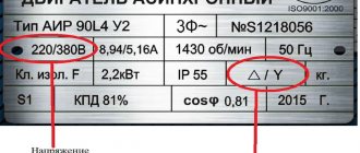
It is worth immediately noting that not all brands of devices operate on a single-phase circuit. But still, the majority allows such manipulations to be carried out on themselves. You should always pay attention to the attached signs. There are all the characteristics, looking at which you can see what model it is and where it will work.
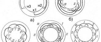
From the first picture (A) we can conclude that this motor is designed for two voltages - 220 and 380 V. The windings are switched on - delta and star. You can run it from a regular home network (there is the appropriate voltage), and preferably with a triangle.
The second (B) shows: the electric machine is designed for 380 V, star switched on. Theoretically, it is possible to switch to a lower voltage, but to do this you need to disassemble the housing, look for the connection of the windings and switch them to a triangle. You can, of course, not switch anything by simply installing a capacitor. However, the power losses will be colossal.
If the sign says: Δ/Ỵ 127/220, then such a device can only be connected to a 220 V network with a star, otherwise it will burn out!
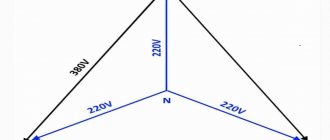
Standard diagram for connecting a three-phase motor to a single-phase network
The process of connecting a three-phase motor to 230 volts is simple. Usually the branch carries a sine wave, the difference is 120 degrees. A uniform phase shift is formed, ensuring smooth rotation of the stator electromagnetic field. The effective value of each wave is 230 volts. This will allow you to connect a three-phase motor to a household outlet. Circus trick: get three sine waves using one. The phase shift is 120 degrees.
In practice, this can be done with the help of special phase shifters. Not those used by high-frequency waveguide paths, but special filters formed by passive, less often active, elements. Fans of troubles prefer to use a real capacitor. If the motor windings are connected in a triangle, forming a single ring, we get phase shifts of 45 and 90 degrees, at least enough for unstable shaft operation:
Connection diagram for a three-phase motor using delta winding switching
- One winding is supplied with the socket phase. The wires pick up the potential difference.
- The second winding is powered by a capacitor. A phase shift of 90 degrees relative to the first is formed.
- On the third, due to the applied voltages, an oscillation slightly similar to a sinusoid is formed with a shift of another 90 degrees.
In total, the third winding is 180 degrees out of phase from the first. Practice shows that the layout is enough to work normally. Of course, the engine sometimes “sticks”, gets very hot, power drops, and efficiency suffers. Users put up with it when connecting an asynchronous motor to a three-phase network is excluded.
From purely technical nuances, let us add: a diagram of the correct wiring layout is given on the device body. More often it decorates the inside of the casing that hides the block, or is drawn nearby on a nameplate. Using the diagram as a guide, we will understand how to connect an electric motor with 6 wires (a pair for each winding). When the network is three-phase (often called 380 volts), the windings are connected in a star. A single point common to the coils is formed, where the neutral (conventional circuit electrical zero) is connected. Phases are supplied to the other ends. It turns out three - according to the number of windings.
It is clear how to handle a delta for connecting a three-phase 230 volt motor. Additionally, we provide a picture depicting:
- Electrical connection diagram of the windings.
- A working capacitor that serves the purpose of creating the correct phase distribution.
- A starting capacitor that facilitates spin-up of the shaft at initial speeds. Subsequently, it is disconnected from the circuit with a button and discharged with a shunt resistor (for safety and to be ready for a new start cycle).
Connecting a three-phase 230 volt motor with a triangle
The picture shows: winding A is energized at 230 volts. At C it is supplied with a phase shift of 90 degrees. Due to the potential difference, the ends of winding B generate a voltage shifted by 90 degrees. The outlines are far from the sinusoid familiar to school physicists. The starting capacitor and shunt resistor have been omitted for simplicity. We believe the location is obvious from the above. This technique will at the very least ensure normal operation of the engine. Using the key, the starting capacitor is closed, performing a start, disconnected from the phase, and discharged by a shunt.
The time has come to say: the capacitance indicated by the drawing 100 µF is practically selected taking into account:
- Shaft rotation speed.
- Engine power.
- Loads placed on the rotor.
You need to select a capacitor experimentally. According to our figure, the voltage of windings B and C will be the same. We remind you: the tester shows the current value. The voltage phases will be different, the waveform of winding B is non-sinusoidal. The effective value shows: equal power is delivered to the shoulders. Provides less stable operation of the installation. The motor heats up less, engine efficiency is optimized. Each winding is formed by inductive reactance, which also affects the phase shift between voltage and current
This is why it is important to choose the correct capacitance value. Ideal engine operating conditions can be achieved
Connecting a phase-shifting capacitor
The optimal option for connecting a three-phase machine to operate from 220 volts is a triangle. So the losses will be about 30%. Two ends in the bourne go directly to the network, and a capacitor is connected between the third end and either of these two.
Such a start is possible if there is no serious load: for example, when a fan is connected. If there is a load, the rotor will either not spin at all, or the startup will take a very long time. In this case, it is worth adding a starting capacitor.
In this case, it would be good to use a switch in which one contact would close and be fixed until it is turned off, and the other would turn off when it is released. This way you can connect the starting capacitor to work for a short time. The direction of rotation is changed by switching the capacitor in the circuit to another phase.
In practice it might look like this:
The circuit for starting a three-phase motor in a single-phase circuit with a star is also simple. The losses will be greater, but sometimes there is simply no other choice.
Connecting a three-phase motor via a manual starter
4. Connecting the motor via a manual starter. PRACTICAL SCHEME
Since motors usually have a high starting current, motor circuit breakers (automatic motors) usually have a thermal protection characteristic of type D. That is it can withstand short-term (starting) overloads of approximately 10 times the nominal value.
Manual motor starter with additional control contact.
Here's what's on the side:
Motor circuit breaker - characteristics on the side wall
Setting current (thermal) – from 17 to 23 A, set manually. Cut-off current (trigger during short circuit) – 297 A.
In principle, a manual starter and an automatic motor are the same device. But the starter shown in the photo can switch the power supply to the engine. And the automatic motor constantly supplies power (three phases) to the contactor, which, in turn, switches the power to the motor. In short, the difference is in the connection diagram.
The advantage of the scheme is that you can adjust the thermal current setting. The disadvantage is the same as in the previous scheme - there is no remote activation.
Capacitor calculation
It is a completely natural question about what parameters a capacitor should be used to start and operate such a device. It all depends on whether the windings on a three-phase machine are star or delta connected.
- For a star there is the following calculation: Cр = 2800•I/U.
- Triangle: Cр = 4800•I/U.
Cp is the capacity of the working capacitor in microfarads, I is the current in amperes, U is the network voltage in volts.
- The current can be calculated this way: I = P/(1.73•U•n•cos f).
P is the power of the asynchronous machine, written on its label, n is its efficiency. It is indicated there, and cos f is written next to it.
There is also a simplified calculation option. It looks like this: C = 70•Pn, where Pn is the rated power, kW (on the tag). From this formula we can conclude that for every 100 W there should be about 7 µF of capacitance.
If the capacitor capacity is too high, the windings will get very hot; if the capacitor is too low, the rotor will be difficult to spin. Therefore, the ideal option is when, after all the calculations, a kind of “adjustment” is made: the current is measured using clamps and additional capacitors are added or removed.
If you need a starting capacitor, then you need to select it so that the total capacitance (Cp + Sp) is 2-3 times higher than the working capacitance (Cp).
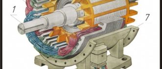
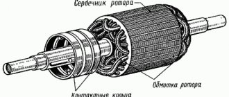
How does a three-phase asynchronous motor work?
In most cases, asynchronous motors use capacitor starting, but there are other starting methods. In three-phase electric motors, unlike single-phase ones, there are three stator windings, which are shifted at a certain angle. The winding angle of the stator windings of a three-phase motor is 120 degrees, which allows you to create a powerful magnetic field around the rotor.
The stator design of a three-phase electric motor consists of the following elements:
- Housings;
- Magnetic core and core with windings;
- Terminal box.
The standard connection of the windings of a three-phase electric motor is made according to the “star” circuit. There is also a less common way to connect the windings of a three-phase motor, namely, a “triangle”. In any case, each stator winding has a specific direction, as well as a beginning and an end.
Arabic numerals are used to number the stator windings of an electric motor: 1, 2, 3. The ends of the windings are designated by a letter and a number: K1, K2, K3, and their beginnings are H1, H2, H3. In some types of electric motors, the marking of the stator windings may have a different designation, for example: C1, C2, C3 and C4, C5, C6.
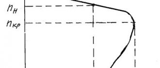
Gradual acceleration
How can you smoothly start an asynchronous motor in a single-phase network? It is worth mentioning right away that for home use this will be expensive. The circuit itself is very complex and there is no point in trying to assemble it yourself. There are special soft starters that are successfully used for this purpose. Their essence lies in the fact that during the first seconds of switching on, the supply voltage is supplied too low, as a result of which the starting torque is reduced.
But since the rotation speed of rotor-type devices depends on the frequency of the supply voltage, and not on its magnitude, this option is suitable only when there is no significant load on the shaft: pumps, fans. If there is a load, then it is best to use a frequency converter. It will also provide a smooth start-up along with many other great features. True, it costs more. The conclusion follows from this: such devices are more suitable for use in production, even small ones. It's expensive for a home.
As you can see, this frequency generator can be powered with either three-phase or single-phase voltage.
Engine, features of coil jumper placement, first connection steps
The first thing you need to pay attention to is the engine nameplate. It states the possibility of single-phase connection, the power of the unit and other information necessary for operation.
Electric motor nameplate - all parameters are indicated on it
It was decided to start assembling the connection diagram from the motor contact group. There are 6 contacts on it - a pair per winding. Initially, the jumpers on them were installed in a row on one side, connecting all 3 windings at one point - in a “star”. This kind of switching is only suitable for a three-phase connection, so they were reinstalled for connection in a “delta”, which we need for a voltage of 220 V. This arrangement can be seen in the photo.
Jumpers are installed in the contact group for triangle connection
Single phase
In order to connect a single-phase asynchronous motor, two buttons are enough: one with a latch, the other without it. Standard circuit: two windings connected in series (although there may be variations depending on the model). The one with greater resistance is the starting one, the other is the working one.
Each model of electric machine has its own characteristics, which means the connection options may vary. Some use two capacitors to start, others use one.
Therefore, you need to start by finding out the model and its technical characteristics.
As you can see, starting short-circuited electric machines is possible in different ways. Connection is possible both at home and at work, which is what made them so popular. And, by and large, nothing better has been invented in more than a hundred years.
Three-phase motor in a single-phase network. Three-phase motor connection diagram
There are situations in life when you need to connect some industrial equipment to a regular home power supply network. A problem immediately arises with the number of wires. Machines intended for use in enterprises usually have three, but sometimes four, terminals. What to do with them, where to connect them? Those who tried to try various options were convinced that the motors simply did not want to spin. Is it even possible to connect a single-phase three-phase motor? Yes, you can achieve rotation. Unfortunately, in this case, the power drop is inevitable by almost half, but in some situations this is the only way out.
Method 3. Using an asynchronous electric motor as a generator
The windings in the stator of such a machine are wound with a shift of 120°.
When three-phase voltage is applied to them, a rotating magnetic field appears, driving the rotor of the electric machine. When connected to a three-phase electric machine to a single-phase voltage network of 220 volts, instead of a rotating field, a pulsating field appears. To drive an electric motor in a single-phase network, the pulsating field is converted into a rotating one.
Reference. In devices made to operate on a 220-volt network, starting windings or stator design features are used for this purpose.
When a 380 by 220 motor is connected to the network, phase-shifting tanks are connected to it. Starting a three-phase motor with 220 without capacitors is possible by driving the rotor into rotation. This will create a shift in the magnetic field, and the electric machine, having lost power, will continue to work. This is how circular machines and other similar mechanisms with low starting torque are turned on.
Each winding of an electric machine has a beginning and an end. They are selected conditionally, regardless of the winding direction, but must correspond to the winding direction of the remaining coils.
Most electric motors are designed to operate with a line voltage of 0.4 kV. In these machines the windings are star-connected. This means that the ends of the windings are connected together, and 3 phases are connected to the beginnings. The voltage on each winding is 220V.
When connected to a network with a linear voltage of 220V, a “triangle” connection is used. In this case, the beginning of the next winding is connected to the end of the previous one.
Some devices with a power of more than 30 kW are manufactured for a network with a linear voltage of 660V. In such devices, when connected to a 0.4 kV network, the windings are connected in a “triangle”.
This method is based on the use of three-phase asynchronous electrical power as a converter/generator from a single-phase 220V electrical network to a three-phase 380V electrical network
The operating procedure is as follows: when connecting the converter/generator to a 220V electrical network, press and hold the SA1 button, thereby connecting the starting capacitor C1 until the electric motor used as the converter/generator reaches operating speed, after which you can open the SA1 button and connect the load to the 380V output.
Disconnection is carried out in the following sequence - we disconnect the three-phase load from the 380V output of the converter/generator, and then disconnect the converter/generator itself from the 220V network.
Any three-phase asynchronous electric motor with windings connected in a star configuration can be used as a converter/generator. The power of this motor must be at least 30% greater than the power of the connected load. It is better for these purposes to use electric motors with a rotor speed of 1000 rpm or less.
The electric motor is connected as a load according to a star circuit.
Design and purpose of capacitors
This element of the electrical circuit consists of two plates (plates). The plates are positioned relative to each other so that there is a gap between them. When a capacitor is connected to an electric current circuit, charges accumulate on the plates. Due to the physical gap between the plates, the device has low conductivity.
Attention! This gap can be air or filled with a dielectric. The following dielectrics are used: paper, electrolyte, oxide films. The main feature of such a two-terminal network is the ability to accumulate electric field energy and instantly transfer it to the load (charge and discharge)
The main feature of such a two-terminal network is the ability to accumulate electric field energy and instantly transfer it to the load (charge and discharge).
Part device
The first prototype of the container was the Leyden jar, created in 1745 in the city of Leiden by the German von Kleist. The jar was lined with copper foil inside and out. This is how the idea of creating covers came about.
Leyden jars connected in parallel
The graphic designation of a two-terminal network on diagrams and drawings is two vertically located lines (like plates) with a gap between them.
Designation on diagrams
CALCULATION OF CAPACITOR FOR THREE-PHASE MOTOR
V. BASHKATOV, Ukraine, Donetsk region, Gorlovka
Sometimes at home it becomes necessary to connect a three-phase AC electric motor to a single-phase network.
The same need arose for me when connecting an industrial sewing machine. In a garment factory, such machines operate in a workshop that has a three-phase network, and no problems arise.
The first thing that had to be done was to change the connection diagram of the electric motor windings from “star” to “triangle”, observing the polarity of the connection of the windings (beginning - end) (Fig. 1). This switching allows you to connect the electric motor to a single-phase 220 V network.
The power of the electric motor of the sewing machine according to the plate is 0.4 kW. Purchasing working, and even more so starting, metal-paper capacitors of the MBGO, MBGP, MBGCh type with a capacity of 50 and 100 microfarads, respectively, for an operating voltage of 450...600 V turned out to be an impossible task due to their high cost on the flea market. Use instead of metal-paper polar (electrolytic) capacitors and powerful rectifier diodes D242, D246. did not give a positive result. The electric motor stubbornly did not start, apparently due to the finite resistance of the diodes in the forward direction.
Therefore, the idea of starting an electric motor, which was absurd at first glance, came to mind by briefly connecting an ordinary electrolytic capacitor to an alternating current network (Fig. 2). After starting (accelerating) the electric motor, the electrolytic capacitor is turned off, and the electric motor operates in two-phase mode, losing up to 50% of its power. But if you provide for a power reserve in advance, or you know that such a reserve exists (as in my case), then you can come to terms with this drawback. By the way, when an electric motor operates with a working phase-shifting capacitor, the electric motor also loses up to 50% of its power.
Now about the most important thing. An electrolytic capacitor, when connected directly to an alternating current network, quickly heats up, the electrolyte boils, and it explodes - many people know this. As the experiment showed, this takes about 10... 15 s. It is known that the resistance of a capacitor in an alternating current circuit of industrial frequency is determined by the formula.
where C is the capacitance of the capacitor in microfarads.
The magnitude of the current in the circuit with a capacitor
But if the electrolytic capacitor is turned on through a small resistance (in my case this is the complex resistance of the motor winding phase Z = r + jx), and also for a short time, during the acceleration of the electric motor (about 1...1.5 s), then the electrolytic capacitor is not damaged because it does not have time to warm up.
Short-term activation can be ensured by the PNVS-10UHL2 button,
used in home washing machines. The button has three contacts: two with latching (SB 1.1, SB1.3) and one without latching (SB 1.2). It turns on the capacitor, and when you stop pressing the button, it returns to its original off position.
Formulas for calculating the starting capacitor have been published several times, but nevertheless I want to repeat them for the connection diagram of the stator winding of an electric motor in a “triangle”.
where U is the network voltage; Iн is the rated current consumed by the electric motor.
where P is the power of the electric motor, kW; U is the network voltage. IN; n is the efficiency of the electric motor (usually 0.8...0.9); cosф - power factor (usually 0.85).
Electrolytic capacitors must have a voltage of at least 450 V. It is advisable to select a capacitance from several capacitors (the thermal conditions are improved). The capacitors are placed in a protective box.
Four years of experience in operating the electric motor have shown the viability of the specified starting scheme. This scheme was repeated by some of my friends, however, the experiments were carried out with electric motors with a power of up to 1 kW. For electric motors larger than 1 kW, during the start-up period, it seems to me that a small current-limiting resistor with the appropriate power dissipation must be connected in series with the capacitor.
Literature
1. Smirnov K.0. Operation of a three-phase electric motor in a single-phase network. - Radio Amateur, 1993, N6, P.27.
2. Kukharenko A. Three-phase electric motor in a single-phase network. - Radio Amateur, 1996, N2, P.28.
CONNECTING A THREE-PHASE INDUCTION MOTOR TO A SINGLE-PHASE 220V NETWORK
S. RYBAS, Modeler - Designer, 2/8
Many tinkerers often try to adapt three-phase electric motors for various homemade machines: sharpening, drilling, woodworking and others. But the problem is that not everyone knows how to power such an electric motor from a single-phase network. Among the various methods of starting three-phase electric motors, the simplest and most effective is by connecting the third winding through a phase-shifting capacitor. The useful power developed by the electric motor is 50-60% of its power in three-phase mode. However, not all three-phase electric motors work well from a single-phase network. These include, for example, electric motors with a double cage squirrel-cage rotor of the MA series. Therefore, preference should be given to three-phase electric motors of the A, DO, AO2, AOL, APN, UAD, etc. series.
- For a capacitor-start electric motor to work properly, the capacitance of the capacitor must change depending on the speed. Since in practice this condition is difficult to fulfill, the engine is usually controlled in two stages - first it is turned on with a starting capacitor, and after acceleration it is disconnected, leaving only the working one.
- If the electric motor's passport indicates a voltage of 220/380 V, then you can turn on the motor in a single-phase network with a voltage of 220 V according to the diagram shown in Figure 1. When you press the SB1 button, the M1 electric motor begins to accelerate, and when it picks up speed, the button is released - SB1 .2 opens, and SB1.1 and SB1.3 remain closed. They are opened to stop the electric motor.
Rice. 1. Electrical diagram for connecting a three-phase electric motor to a single-phase network.
When connecting the windings of an electric motor in a “triangle”, the capacitance of the working capacitor is determined by the formula: where Cp is the capacitance of the capacitor, μF; I is the current consumed by the electric motor, A; U is the network voltage, V. If the power of the electric motor is known, the current consumed by it is determined by the formula: where P is the power of the electric motor (indicated in the passport), W; U—mains voltage, V; n —
efficiency;
cosф -
power factor. The capacitance of the starting capacitor is chosen to be 2-2.5 times greater than the working capacitor, and their permissible voltages must be at least 1.5 times the network voltage. For a 220 V network, it is better to use capacitors of the MBGO, MBGP, MBGCh brands with an operating voltage of 500 V and higher. Electrolytic capacitors K50-3, EGC-M, KE-2 with an operating voltage of at least 450 V (subject to short-term switching) can also be used as starting capacitors. For greater reliability, they are connected according to the circuit shown in Figure 2. The total capacity is equal to C/2. Shunt the starting capacitors with a resistor with a resistance of 200-500 kOhm, through which the remaining electrical charge will “drain”.
Rice. 2. Connection diagram of electrolytic capacitors.
The operation of an electric motor with capacitor starting has some peculiarities.
When operating in idle mode, a current flows through the winding fed through the capacitor, 20-40% higher than the rated one. Therefore, if the electric motor will often be used in underloaded mode or idle, the capacitance of the capacitor Cp should be reduced. If overloaded, the electric motor may stop; then to start it, reconnect the starting capacitor (by removing or reducing to a minimum the load on the shaft). In practice, the capacitance values of working and starting capacitors, depending on the power of the electric motor, are determined from the table. Three-phase electric motor power, kW
| 0,4 | 0,6 | 0,8 | 1,1 | 1,5 | 2,2 | |
| Minimum capacitance of the capacitor Ср, µF | 40 | 60 | 80 | 100 | 150 | 230 |
| Starting capacitor capacity (Cn), µF | 80 | 120 | 160 | 200 | 250 | 300 |
To start the electric motor at idle or with a light load, the capacitance of the capacitor Cn can be reduced. For example, to turn on an AO2 electric motor with a power of 2.2 kW at 1420 rpm, you can use a 230 µF capacitor as a working capacitor, and a starting capacitor - 150 µF. In this case, the electric motor starts confidently with a small load on the shaft. Reversing the electric motor is carried out by switching the phase on its winding with toggle switch SA1 (Fig. 1).
Rice. 3. Electrical circuit of the starting device for a three-phase electric motor with a power of 0.5 kW.
Figure 3 shows an electrical diagram of a portable universal unit for starting three-phase electric motors with a power of about 0.5 kW from a single-phase network without reversing. When you press the SB1 button, the magnetic starter KM1 is triggered (toggle switch SA1 is closed) and its contact system KM1.1, KM1.2 connects the electric motor M1 to the 220 V network. At the same time, the third contact group KM1.3 blocks the SB1 button. After complete acceleration of the electric motor, the starting capacitor C1 is turned off using toggle switch SA1. Stop the electric motor by pressing button SB2. The device uses a magnetic starter of the PML type, designed for alternating current with a voltage of 220 V; SB1, SB2 - paired PKE612 buttons, SA1 - toggle switch T2-1; resistors: R1 - wire PE-20, R2 - MLT-2, C1, C2 - MBGCh capacitors for a voltage of 400 V (C2 is made up of two parallel-connected capacitors of 20 μF X 400 V); HL1 - KM-24 lamp (24 V, 100 mA). M1 - electric motor 4A71A4 (AO2-21-4) 0.55 kW, 1420 rpm.
- The starting device is mounted in a tin casing measuring 170x140x70 mm (Fig. 4). On the top panel there are “Start” and “Stop” buttons, a signal lamp and a toggle switch for turning off the starting capacitor. On the front side wall there is a homemade three-pin connector made from three pieces of copper tube and a round electrical plug, in which a third pin is added.
Rice. 4. Appearance of the starting device: 1 - housing, 2 - carrying handle, 3 - signal lamp, 4 - toggle switch for turning off the starting capacitor, 5 - “Start” and “Stop” buttons, 6 - modified electrical plug, 7 - panel with sockets connector
Using the SA1 toggle switch (Fig. 3) is not entirely convenient. Therefore, it is better if the starting capacitor is turned off automatically using an additional relay K1 (Fig. 5) of the MKU-48 type. When you press the SB1 button, it is triggered and its contact pair K1.1 turns on the magnetic starter KM1, and K1.2 turns on the starting capacitor Sp. In turn, the magnetic starter KM1 is self-locking using its contact system KM1.1, and KM1.2 and KM1.3 connect the electric motor to the network. The SB1 button is kept pressed until the electric motor fully accelerates, and then released - relay K1 is de-energized and turns off the starting capacitor, which is discharged through resistor R2. At the same time, the magnetic starter KM1 remains turned on, providing power to the electric motor in operating mode. Stop the electric motor by pressing the SB2 “Stop” button.
Rice. 5. Electrical circuit of the starting device with automatic shutdown of the capacitor Sp.
In conclusion, a few words about improvements that expand the capabilities of the starting device. Capacitors Cp and Sp can be made composite in steps of 10-20 µF and connected with multi-position switches (or two to four toggle switches) depending on the parameters of the electric motors being started. We recommend replacing the HL1 incandescent lamp with a quenching wire-wound resistor with a neon lamp with an additional low-power resistor; instead of paired PKE612 buttons, use two single buttons of any type; fuses can be replaced with automatic fuses for the appropriate cut-off current.
STARTING A THREE-PHASE MOTOR FROM A SINGLE-PHASE NETWORK WITHOUT LOSS OF POWER
"Radio" No. 7, 2000 S. BIRYUKOV, Moscow
In various amateur electromechanical machines and devices, three-phase asynchronous motors with a squirrel cage rotor are most often used. Unfortunately, a three-phase network in everyday life is an extremely rare phenomenon, so to power them from a regular electrical network, amateurs use a phase-shifting capacitor, which does not allow the full power and starting characteristics of the engine to be realized. Existing thyristor “phase-shifting” devices reduce the power on the motor shaft to an even greater extent.
A variant of the circuit diagram for starting a three-phase electric motor without loss of power is shown in Fig. 1 . The 220/380 V motor windings are connected in a triangle, and capacitor C1 is connected, as usual, in parallel with one of them. The capacitor is “helped” by inductor L1, connected in parallel with the other winding. With a certain ratio of the capacitor C1, the inductance of the inductor L1 and the load power, you can obtain a phase shift between the voltages on the three load branches equal to exactly 120°. In Fig. Figure 2 shows a vector voltage diagram for the device shown in Fig. 1 , with a purely active load R in each branch.
Linear current Il in vector form is equal to the difference between currents Iz and Ia, and in absolute value it corresponds to the value Iph, where Iph=I1=I2=I3=Ul/R is the phase load current, Ul=U1=U2=U3=220 V is linear mains voltage. Voltage Uc1=U2 is applied to capacitor C1, the current through it is equal to Ic1 and is 90° ahead of the voltage in phase. Similarly, voltage UL1=U3 is applied to inductor L1, the current through it IL1 lags behind the voltage by 90°. If the absolute values of the currents Ic1 and IL1 are equal, their vector difference, with the correct choice of capacitance and inductance, can be equal to Il. The phase shift between the currents Ic1 and IL1 is 60°, therefore the triangle of vectors Il, Ic1 and IL1 is equilateral, and their absolute value is Ic1=IL1=Il=Iph.
In turn, phase load current Iph = P/ЗUL, where P is the total load power. In other words, if the capacitance of capacitor C1 and the inductance of inductor L1 are chosen such that when a voltage of 220 V is applied to them, the current through them would be equal to Ic1=IL1=P/(Uл)=P/380, shown in Fig. 1 circuit L1C1 will provide three-phase voltage to the load with precise phase shift.
In table 1 shows the current values Ic1=IL1. the capacitance of the capacitor C1 and the inductance of the inductor L1 for various values of the total power of the purely active load. A real load in the form of an electric motor has a significant inductive component. As a result, the linear current lags in phase from the active load current by a certain angle φ of the order of 20...40°. On the nameplates of electric motors, it is usually not the angle that is indicated, but its cosine - the widely known one, equal to the ratio of the active component of the linear current to its total value. The inductive component of the current flowing through the load of the device shown in Fig. 1 , can be represented in the form of currents passing through some inductors Ln, connected in parallel with active load resistances (Fig. 3, a) , or, equivalently, in parallel with C1, L1 and network wires.
From Fig. 3b it is clear that since the current through the inductance is antiphase to the current through the capacitance, the inductors LH reduce the current through the capacitive branch of the phase-shifting circuit and increase it through the inductive one. Therefore, to maintain the phase of the voltage at the output of the phase-shifting circuit, the current through capacitor C1 must be increased and decreased through the coil.
The vector diagram for a load with an inductive component becomes more complex. Its fragment, which allows you to make the necessary calculations, is shown in Fig. 4 . The total linear current Il is decomposed here into two components: active and reactive. As a result of solving the system of equations to determine the required values of currents through capacitor C1 and coil L1, we obtain the following values of these currents.
With a purely active load, the formulas give the previously obtained result Ic1 = IL1 = Il. In Fig. Figure 5 shows the dependences of the ratios of currents Ic1 and IL1 to Il on , calculated using these formulas For ( /2 = 0.87), the capacitor current C1 is maximum and equal to and the inductor current L1 is half as much. The same relationships can be used with a good degree of accuracy for typical values equal to 0.85–0.9.
In table Figure 2 shows the values of currents Ie1, IL1 flowing through capacitor C1 and inductor L1 at various values of the total load power having the above value. For such a phase-shifting circuit, use capacitors MBGO, MBGP, MBGT, K42-4 for an operating voltage of at least 600 V or MBGCh , K42-19 for a voltage of at least 250 V. The choke is most easily made from a rod-type power transformer from an old tube TV. The no-load current of the primary winding of such a transformer at a voltage of 220 V usually does not exceed 100 mA and has a nonlinear dependence on the applied voltage. If a gap of the order of 0.2 1 mm is introduced into the magnetic circuit, the current will increase significantly, and its dependence on voltage will become linear. The network windings of vehicle transformers can be connected so that the rated voltage on them is 220 V (jumper between pins 2 and 2′), 237 V (jumper between pins 2 and 3′) or 254 V (jumper between pins 3 and 3′) Mains voltage is most often supplied to terminals 1 and 1′. Depending on the type of connection, the inductance and current of the winding change. Table. Table 3 shows the current values in the primary winding of the TS-200-2 transformer when a voltage of 220 V is applied to it at different gaps in the magnetic core and different inclusions of winding sections. Comparison of the data in Tables 3 and 2 allows us to conclude that the specified transformer can be installed in the phase-shifting circuit of the motor with power from approximately 300 to 800 W and, by selecting the gap and winding connection circuit, obtain the required current value. The inductance also changes depending on the in-phase or anti-phase connection of the mains and low-voltage (for example, incandescent) windings of the transformer. The maximum current may slightly exceed the rated current in operating mode. In this case, to ease the thermal regime, it is advisable to remove all secondary windings from the transformer; some of the low-voltage windings can be used to power the automation circuits of the device in which the electric motor operates.
In table Figure 4 shows the nominal values of the currents of the primary windings of transformers of various televisions [1, 2] and the approximate values of the motor power with which it is advisable to use them. The phase-shifting LC circuit should be calculated for the maximum possible load of the electric motor.
At a lower load, the required phase shift will no longer be maintained, but the starting characteristics will improve compared to using a single capacitor. Experimental testing was carried out both with a purely active load and with an electric motor. The functions of the active load were performed by two parallel-connected incandescent lamps with a power of 60 and 75 W, included in each load circuit of the device (see Fig. 1) , which corresponded to a total power of 400 W. In accordance with Table 1, the capacitance of capacitor C1 was 15 μF Gap in the magnetic circuit of the TS transformer -200-2 (0.5 mm) and the winding connection circuit (at 237 V) were chosen to ensure the required current of 1.05 A. The voltages U1, U2, U3 measured on the load circuits differed from each other by 2.. 3 B, which confirmed the high symmetry of the three-phase voltage. Experiments were also carried out with a three-phase asynchronous motor with a squirrel-cage rotor AOL22-43F with a power of 400 W [Z]. He worked with capacitor C1 with a capacity of 20 μF (by the way, the same as when the engine was running with only one phase-shifting capacitor) and with a transformer, the gap and connection of the windings of which were selected from the condition of obtaining a current of 0.7 A. As a result, it was possible to quickly start the engine without starting capacitor and significantly increase the torque felt when braking the pulley on the motor shaft. Unfortunately, it is difficult to carry out a more objective check, since in amateur conditions it is almost impossible to ensure the normalized mechanical load on the engine. It should be remembered that the phase-shifting circuit is a series oscillatory circuit tuned to a frequency of 50 Hz (for a purely active load option), and this circuit cannot be connected to the network without a load.
LITERATURE 1 Kuzinets L. M., Sokolov V. S. Units of television receivers - M Radio and communications 1987 2 Sidorov I. N., Binnatov M. F., Vasiliev E. A. Power supply devices for household electronic equipment - M Radio and communications, 1991 3 Biryukov S. Automatic water pumping. - Radio, 1998, No. 5, pp. 45,46.
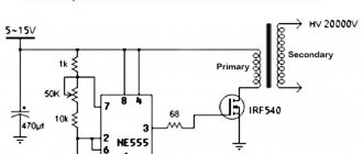
ELECTRONIC STARTING OF A THREE-PHASE MOTOR FROM A SINGLE-PHASE NETWORK
A. DUBROVSKY, Novopolotsk, Vitebsk region, Belarus
In the home “workshops” of radio amateurs, there are electromechanical machines and various devices driven by three-phase asynchronous motors. However, in everyday life there is often no three-phase network, so a phase-shifting capacitor is often used to power them. Unfortunately, this leads to a decrease in the required power on the electric motor shaft and also eliminates the possibility of regulating the rotation speed. Using the proposed device, it is possible not only to power a three-phase asynchronous electric motor from a single-phase network, but also to smoothly regulate its rotation frequency. The speed controller significantly improves the characteristics of a three-phase asynchronous motor (TAM). The described device allows you to power the TJM from a single-phase network with virtually no loss of power, regulate the starting torque, regulate the rotation speed within a wide range both at idle and under load, and most importantly, increase the maximum rotation speed above the nominal one. The proposed device is operated with a TJM with a power of 120 W and a nominal rotation speed of 3000 rpm. As is known, there are several ways to regulate the rotation speed of a TJM - by changing the supply voltage, the load on the shaft, or using a special rotor winding with adjustable resistance. However, frequency regulation is the most effective, since it allows you to maintain energy characteristics and use the cheapest and most reliable electric motors with a short-circuited rotor winding - a “squirrel cage”.
SPEED CONTROLLER FOR THREE-PHASE INDUCTION MOTORS
The schematic diagram of the rotation controller of a three-phase asynchronous motor is shown in Fig. 1. A master oscillator with a frequency variable within 30...800 Hz is assembled on elements DD1.1—DD1.3. The frequency is adjusted with variable resistor R3. Counter DD2, NAND element DD1.4 and four XOR elements DD3.1-DD3.4 are part of a three-phase sequence pulse shaper (FIT), which converts DC voltage into rectangular signals, phase-shifted by 120 degrees. In Fig. Figure 2 shows voltage diagrams at characteristic points. Three identical amplifiers are assembled on transistors 1VT1—1VT6, 2VT1—2VT6, 3VT1—3VT6, one for each phase of the TAD. In Fig. Figure 1 shows a diagram of only one amplifier. The rest of the schemes are exactly the same. Let's consider the work of one of them (the top one in the diagram). When a high level appears at the output of element DD3.2, the composite transistor 1VT4, 1VT5 opens, and the output transistor 1VT6 closes. In addition, a high level is supplied to the input of the transistor optocoupler 1U1, as a result of which a low level is set at its output, which closes the composite transistor 1VT1, 1VT2. Output transistor 1VT3 is open. For voltage decoupling, transistors 1VT1, 1VT2 and 1VT4, 1VT5 are supplied from different sources with a voltage of +10 V, and transistors 1VT3, 1VT6 are supplied from a source with a voltage of +300 V. Diodes 1VD3, 1VD4, 1VD6, 1VD7 are used for more reliable closing of the output transistors. One of the main conditions for the normal operation of transistors 1VT3 and 1VT6 is that they should not be open at the same time. To do this, the control voltage is supplied to the input of the composite transistor 1VT1, 1VT2 from the output of the optocoupler 1U1, which provides a certain delay in its switching (approximately 40 μs). When a high level optocoupler appears at the input, capacitor 1C2 begins to charge. A low-level signal at the input of the optocoupler cannot instantly close the composite transistor 1VT4, 1VT5, since the capacitor 1C2, discharging through the circuit 1R3, the emitter junctions of the transistors, maintains it in the open state for about 140 μs, and the transistor 1VT6 in the closed state. The turn-off time of the optocoupler is approximately 100 μs, so transistor 1VT3 closes earlier than transistor 1VT6 opens. Diodes 1VD5, 1VD8 protect the output transistors from increasing voltage when switching an inductive load - TAD windings, and also close the current of the windings when the voltage on them changes its polarity (when switching transistors 1VT3, 1VT6). For example, after closing transistors 1VT3 and 2VT6, the current flows for some time in the same direction - from phase A to phase B, closing through diode 2VD5, power supply, diode 1VD8, until it decreases to zero.
Timing diagrams on some pins of the microcircuits
Let's consider the switching sequence of output transistors using phases A and B as an example. When transistors 1VT3 and 2VT6 are open, current flows through the circuit: source +300 V, collector-emitter section of transistor 1VT3, windings of phase A and phase B, collector-emitter section of transistor 2VT6. When these transistors close and 1VT6 and 2VT3 open, current flows in the opposite direction. Thus, rectangular voltage pulses with a phase shift of 120 degrees are applied to phases A, B and C. (Fig. 2). The frequency of the TAD supply voltage is determined by the switching frequency of these transistors. Thanks to the alternate opening of the transistors, the current passes sequentially through the stator windings AB-AC-BC-WA-SA-SV-AB, which creates a rotating magnetic field. The design of the output stages described above is a three-phase bridge [1-3]. Its advantage lies in the fact that there are no third harmonic components in the phase current. The regulator's power supply produces voltages of +5, +10 and +300 V. The +5 V voltage generated by the stabilizer on the zener diode VD3 and transistor VT1 is used to power microcircuits DD1-DD3. The upper composite transistor of each amplifier in the circuit is powered from a separate winding of the network transformer T1 and a separate bridge rectifier (WD1, 2VD1, 3VD1). The lower composite transistor of all amplifiers is from winding II and diode bridge VD2. To power the output transistors, a VD1 bridge and an LC filter C2L1C3 are used. The capacitance of capacitors C2 and SZ is selected based on the power of the TAD. It must be at least 20 μF with an inductance of 0.1 H. The regulator can use fixed resistors MLT, OMLT, BC. Capacitor C1 - any, for example, ceramic K10-17-26, C2-C5, 1S1, 2S1, ZS1 - any oxide. Throttle L1 is homemade. It is wound on a W-shaped magnetic wire with a cross-sectional area of 4 cm2. The winding contains 120 turns of PEV 0.35 wire. The choke can be eliminated, but in this case the capacitance of capacitors C2 and SZ will have to be increased to 50 µF. Optocouplers 1U1, 2U1, 3U1 can also be used with others whose turn-on delay time is no more than 100 μs, and the insulation voltage is no less than 400 V. The main requirement for transistors is a high and approximately the same current transfer coefficient for all (at least 50). KT315A transistors can be replaced with transistors of the KT315, KT312, KT3102 series with any letter indices, and KT817A transistors (VT1, 1VT2, 1VT5, 2VT2, 2VT5, 3VT2. 3VT5) - with KT817 or KT815 with any letter indices. Instead of KT858A transistors, you can use any powerful ones with an allowable collector-emitter voltage of at least 350 V and a current transfer coefficient of at least 50. They should be installed on heat sinks with an area of at least 10 cm2 each. However, when using electric motors with a power of more than 200 W, heat sinks with a larger area will be required. If the TAD power exceeds 300 W, instead of the KTs409A rectifier, it is necessary to assemble a bridge from individual diodes designed for a reverse voltage of more than 400 V and the corresponding current. Diodes 1VD5, 1VD8 are suitable for any with a permissible forward pulse current of at least 5 A and a reverse voltage of at least 400 V, for example, KD226V or KD226G. Transformer - any power of at least 15 W, having four separate secondary windings of 8...9 V each. When setting up the device, first turn off the +300 V voltage and check the presence of all signals in accordance with Fig. 2. If necessary, by selecting capacitor C1 or resistor R2, the frequency at the collector of transistor 1VT2 (1VT5) is changed within 5...130 Hz. Then, with the TAD turned off, instead of +300 V, a voltage of +100 ... 150 V is supplied from an external source, the collector and emitter of transistor 1VT2, the collector and emitter of transistor 1VT5 are closed (to close transistors 1VT3 and 1VT6) and the current is measured in the collector circuit of transistor 1VT3, which should be no more than a few milliamps - leakage current of the output transistors. Next, the collectors and emitters of the above transistors are opened and resistor R2 is set to the maximum frequency. By selecting capacitor 1C2 (in the direction of increasing the capacitance), the minimum current value in the collector circuit of transistor 1VT3 is achieved. The rest of the amplifiers are adjusted in the same way. After this, an electric motor is connected to the output of the regulator, the windings of which are connected by a star. Instead of +300 V, a voltage within +100 ... 150 V is supplied from an external source. The electric motor rotor should begin to rotate. When it is necessary to change the direction of rotation, any two phases of the TAD are swapped. If the output transistors operate in the correct mode, they remain slightly warm for a long time, otherwise the resistance of resistors 1R6, 1R8, 2R6, 2R8, 3R6, 3R8 is selected.
Literature 1. Radin V.I. Electrical machines: Asynchronous machines.
— M.: Higher school. 1988. 2. Kraachik A.E. Selection and application of asynchronous motors. - M.: Energoatom publishing house. 1987. 3. Lopukhina E. M. Asynchronous executive micromotors for automation systems. - M.: Higher School, 1988. Address of the site administration
Reverse
To change the direction of rotation of the rotor, you need to switch the capacitive circuit to another wire or terminal of the electric motor box. A phase is supplied to one terminal, zero to the other, and the capacitor group is switched on to the third. Now, when the second wire of the capacitor is connected to the phase, the motor rotates in one direction, and when connected to zero, in the other.
This is enough to figure out how to connect a three-phase motor to 220, but if everything worked out and it seems to be working correctly, it turns, does not heat up, does not burn, a simple and in this case optional check will help to finally make sure that the assembled circuit is correct. While working with a constant, identical load, use a current clamp to measure the currents in the phase, neutral and capacitor wires. Ideally, they should be equal to each other; if there are small differences (30 percent), then this is not ideal, but still good.
And the difference in currents is corrected simply - by changing the capacitance of the working capacitor. It is necessary not to make sudden movements and not to burn the winding by installing too large a capacity of the working capacitor.