Where you should definitely start connecting the engine: 2 important time-tested points
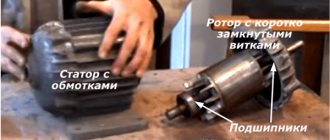
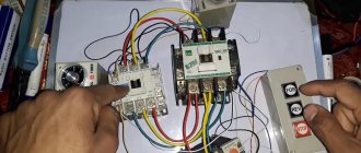
Before turning on any electric motor for the first time, it is necessary to clarify its structure: the design of the stator and rotor, the condition of the bearings.
From my own and other people’s experience, I can assure you that it is easier to loosen a few nuts, inspect the internal structure, identify defects at the initial stage and eliminate them, than to deal with complex repairs that could have been prevented after starting a short operation.
Important Warning
Novice electricians quite often create engine malfunctions themselves, violating the technology for disassembling it, working with an ordinary hammer: they break the edges of the shaft.
To preserve the structure of parts without damaging them, it is necessary to use a special electric motor bearing puller.
In the most extreme case, when it is not available, blows with a hammer are applied through thick plates of soft metal (copper, aluminum) or dense dry wood (apple tree, pear tree, oak).
How bearing condition affects engine performance
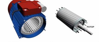
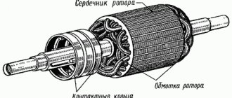
Any asynchronous electric motor (IM) has a rotor with squirrel-cage windings. A current is induced in them, creating a magnetic flux that interacts with the rotating magnetic field of the stator, which is its source of movement.
The rotor inside the housing is mounted on bearings. Their condition greatly affects the quality of rotation. They are designed to ensure easy sliding of the shaft without backlash or runout. Any violations are unacceptable.
The fact is that the stator winding can be considered as an ordinary electromagnet. If the rotor's bearings are broken, then under the influence of the magnetic field it will begin to be attracted, approaching the stator winding.
The gap between the rotating and stationary parts is very small. Therefore, touching or beating the rotor can touch, scratch, or deform the stator windings, irreversibly damaging them. The repair will require a complete rewinding of the stator, and this is a very difficult job.
Be sure to disassemble the electric motor before connecting it, and carefully inspect its entire internal structure.
Pay special attention to the condition of the bearings, compliance with tolerances and fits, and quality of lubrication. Dry and old lubricant must be replaced with fresh one.
What should be taken into account in the design of stator windings and how to prepare them
The home mechanic most often comes across electric motors that have already been used somewhere, and, perhaps, have undergone reconstruction or rewinding. Nobody usually declares this, the information on nameplates and tags is not changed, it is left the same. Therefore, I recommend visually inspecting their insides.
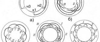
Stator coils for asynchronous motors for power supply from single-phase and three-phase networks differ in the number of windings and design.
A three-phase electric motor has three absolutely identical windings, spaced apart in the direction of rotation of the rotor by 120 angular degrees. They are made of one wire with the same number of turns.
They all have equal active and inductive resistance and occupy the same number of slots inside the stator.
This allows you to initially assess their condition with a conventional digital multimeter in ohmmeter mode with the voltage turned off.
A single-phase induction motor has two different windings on the stator, separated by 90 angular degrees. One of them is designed for long-term passage of current in the nominal operating mode and is therefore called the main, main or working.
To reduce heating, it is made with a thicker wire that has lower electrical resistance.
A second winding of greater resistance and smaller diameter is mounted perpendicular to it, which makes it possible to distinguish it visually. It is designed for short-term flow of starting currents and turns off immediately when the rotor reaches the rated speed.
The starting or auxiliary winding occupies approximately 1/3 of the stator slots, and the rest is allocated to the working turns.
However, this rule has exceptions: in practice, there are single-phase electric motors with two identical windings.
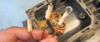
To connect the stator to the power supply, the ends of the windings are brought out with wires. Taking into account the fact that one winding has two ends, a three-phase electric motor can, as a rule, have six terminals, and a single-phase motor can have four.
But there are exceptions to this simple rule related to internal switching of pins to simplify installation on special equipment:
- for three-phase motors, the following can be removed from the stator: three wires when internally assembling a delta circuit;
- or four - for a star;
- three outputs with internal combination of one end of the starting and working windings;
- or six ends for a design with a starting winding and a built-in contact for disconnecting it from the centrifugal regulator.
As you can see, it is possible to judge the design of an asynchronous motor by the number of wires connected to the terminal block from the stator windings, but the probability of error is quite high. A more thorough analysis of its structure is needed.
Technical condition of winding insulation
Where and under what conditions the stator was stored is not always known. If it was unprotected from precipitation or inside wet rooms, then its insulation requires drying.
At home, the disassembled stator can be placed in a dry room to dry. It is possible to speed up the process by blowing a fan or heating with conventional incandescent lamps.
Make sure that the heated glass of the lamp does not touch the winding wire; ensure an air gap. The end of the drying process is associated with the restoration of the insulation properties. This process must be controlled by measurements with a megohmmeter.
Methods by which this electric motor can be made self-starting
These motors do not start themselves because the stator magnetic flux produced is variable in nature and when started the 2 components of this flux cancel each other and therefore no torque is produced.
This problem can be solved by making the stator magnetic flux a rotating type, rather than an alternating type, which rotates only in one direction. Then the motor will become self-starting. Now, in order to produce this rotating magnetic field, you will need two alternating magnetic fluxes having a phase angle with some difference between them.
When these two fluxes interact, they produce a net magnetic flux. This flow is inherently rotating and rotates in space in only one direction. When the motor begins to rotate, the additional magnetic flux can be removed.
The motor will continue to rotate under the influence of only the main magnetic flux. Depending on the methods of converting an induction motor into a self-starting motor, there are mainly 4 types of single-phase induction motors, namely:
1. Sliding phase induction motor.
2. Capacitive electric motor with a starting inductor.
3. Capacitive induction electric motor with a starting capacitor.
4. Shaded pole induction motor.
5. Permanent slip capacitive motor or single value capacitive motor.
Connection diagram for an asynchronous motor with a starting winding: assembly sequence
For example, we have determined that there are four or three wires coming out of the stator. We call up the active resistance between them with an ohmmeter and determine the starting and operating windings.
Let’s assume that four wires have two pairs with resistances of 6 and 12 ohms connected to each other. Let's randomly twist one wire from each winding, designate this place as a “common wire” and get a measurement of 6, 12, 18 Ohms between the three terminals.
I marked the beginnings of the windings with dots on this diagram. For now, ignore this question. But, you will need to return to it further when the need arises to reverse.
The chain between the common terminal and the lower resistance 6Ω will be the main one, and the larger 12Ω will be the auxiliary, starting winding. Connecting them in series will show a total result of 18 ohms.
We mark these 3 ends with markings that are already clear to us:
- O - general;
- P - starting;
- R - worker.
Next we need a PNVS button, specially designed for starting single-phase asynchronous motors. Its electrical circuit is represented by three closing contacts.
But, it has an important difference from the start button of three-phase NVD electric motors: its middle contact is made with self-return, and not fixed when pressed.
This means that when the button is pressed, all three contacts are closed and held in that position. But, when you release your hand, the two outer contacts remain closed, and the middle one returns under the action of the spring to the open state.
We connect this button and the terminals for the output of the stator windings from the electric motor with a three-core cable so that the starting winding contact goes to the middle contact of the PNVS. We connect pins P and P to its outermost contacts and mark them.
On the back side of the button, between the contacts of the starting and working windings, we rigidly mount a jumper. We connect a 220 volt household power cable with a plug for installation in a socket to it and the second outer contact.
When this button is turned on, all three contacts will close, and the working and starting windings will begin to work. In just a couple of seconds the engine will finish accelerating and return to nominal mode.
Then the start button is released:
- the starting winding is switched off by self-return of the middle contact;
- the main winding of the motor continues to spin the rotor from a 220 V network.
This is the most affordable connection diagram for an asynchronous motor with a starting winding for the home craftsman. However, it requires the presence of a ventilator button.
If it is not there, and the electric motor urgently needs to be started, then it can be replaced with a combination of a two-pole circuit breaker and a conventional electric button of the appropriate power with self-reset.
You will have to turn them on at the same time, and release the button after spinning up the electric motor.
Always perform all starts of electric motors and any electrical equipment with the protection of these circuits by circuit breakers. They will prevent the development of emergency situations when any random errors occur.
In order to consolidate the material on this topic, I recommend watching the video of the owner Oleg pl. It just shows the design of a built-in centrifugal regulator designed to automatically turn off the auxiliary winding.
Wiring diagram for an asynchronous motor with capacitor start: 3 technologies
The stator with windings for starting from capacitors has approximately the same design as discussed above. It is difficult to distinguish it by appearance and simple measurements with a multimeter, although the windings may have equal resistance.
Refer to the nameplate and table from Aliyev’s book. You can try to connect such an electric motor using a circuit with a PNVS button, but it will not spin up.
It will not have enough starting torque from the auxiliary winding. It will hum and twitch, but will not reach the rotation mode. Here you need to assemble a different capacitor starting circuit.
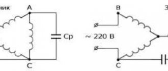
The 2 ends of different windings are connected to a common terminal O. A household voltage of 220 volts is supplied to it and the second end of the working winding through an AB switching device.
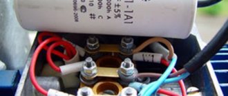
The capacitor is connected to the terminals of the starting and operating windings.
As a switching device, you can use a double circuit breaker, a switch, NVD or NVDS type buttons.
Here it turns out that:
- the main winding operates directly from 220 V;
- auxiliary - only through the capacitor.
This circuit is used for easy starting of capacitor electric motors that are put into operation without heavy load on the drive, for example, fans, sanders.
If, at the moment of starting, it is necessary to simultaneously spin the belt drive, gear mechanism of the gearbox or other heavy drive, then a starting capacitor is added to the circuit, which increases the starting torque.
It is convenient to describe the operating principle of such a scheme using the same PVS button.
Its self-resetting contact is connected to the auxiliary winding through an additional starting capacitor Sp. The second end of its plate is connected to terminal P and working capacity Cp.
An additional capacitor at the moment of starting an electric motor with a heavy drive helps it quickly reach its rated rotation speed, and then simply turns off so as not to create overheating of the stator.
This circuit is fraught with one danger associated with long-term storage of a capacitive charge by the starting capacitor after removing power 220 when the electric motor is turned off.
If the worker is not careful or careless, the discharge current can pass through the human body. Therefore, the charged capacity must be discharged.
In the scheme under consideration, after removing the voltage and pulling out the plug and power cord from the socket, this can be done by briefly turning on the PVS button. Then the capacitance Sp will begin to discharge through the starting winding of the motor.
However, not all people do this for various reasons. Therefore, it is recommended to install two additional resistors in the starting circuit.
Resistance Rр is selected with a nominal value of about 300÷500 Ohms of several watts. Its task is to discharge the auxiliary capacitance Sp after removing the supply voltage.
The Ro resistor is low-resistance and powerful and acts as a current-limiting resistance.
Adding resistors to the electric motor starting circuit increases the safety of its operation and automatically limits the flow of capacitive discharge current of a charged capacitor through the human body.
Where can I get the values of the main and auxiliary capacitors?
The fact is that the factory determines the value of the starting and operating capacitance for capacitor starting of a single-phase IM individually for each model and indicates this value in the passport.
There are simply no separate formulas for calculating how it is done for capacitor starting of a three-phase motor in a single-phase network using star or delta circuits.
You will need to look for factory recommendations or experiment during the setup process with different containers, choosing the most optimal option.
The owner of the video “IV I'm Interested” shows how to optimally configure the parameters of a capacitor motor starting circuit.
Disadvantages of single-phase current
Theory and practice show that single-phase current cannot independently make a single-phase electric motor move. This is due to the fact that current of this format does not create a magnetic field, so the rotor will not move. To do this, two windings are created in the motors, located at a certain angle to each other. All single-phase 220 V motors used in household appliances are identical. In fact, the disadvantages are minimal, since the use of such equipment models greatly simplifies a person’s life.
The use of alternating current allows you to connect any type of single-phase motor to simple sockets. You can remove them from the compressor and put them on lawn mowers or washing machines.